

 EN
EN

 English
 русский
 Français
 Español
 عربى
عربى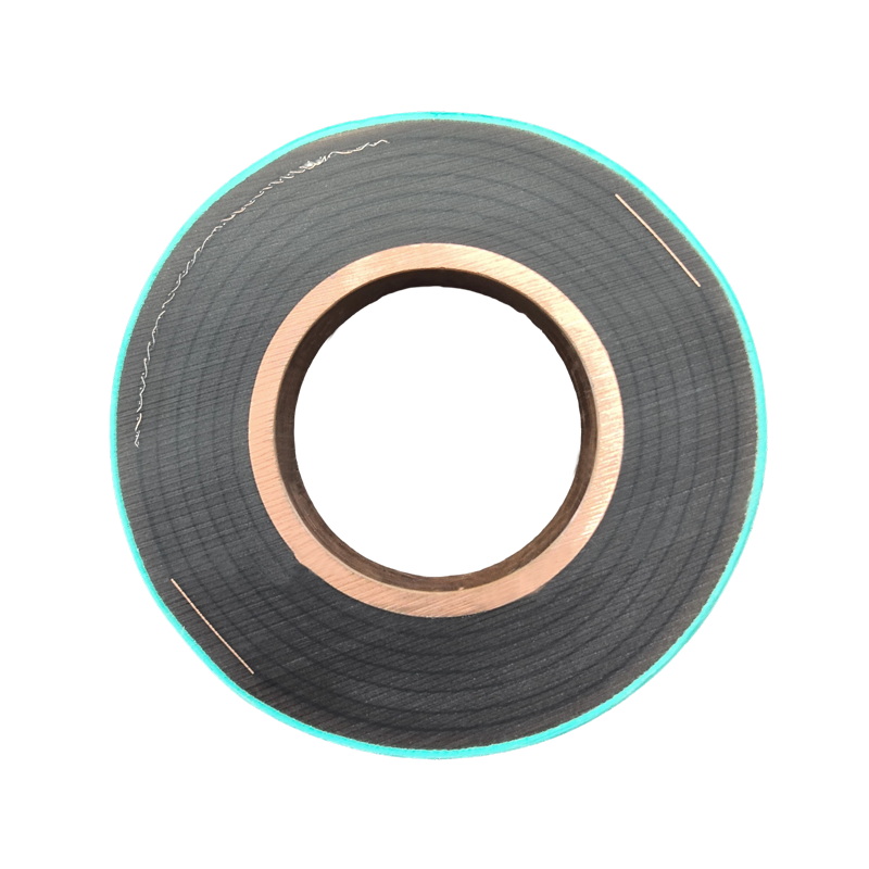
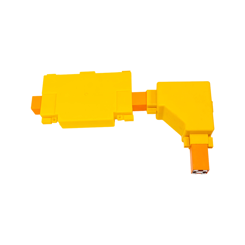

PTFE Tubular Bus Bar for Extreme-Environment Power Transmission
Content
- 1 1. Overview of PTFE Tubular Bus Bar Technology
- 2 2. Construction of the Insulated Tubular Busbar
- 3 3. Main Technical Advantages
- 4 4. Comparison with Other Insulated Busbar Technologies
- 5 5. Manufacturing Process and Quality Control
- 5.1 5.1 Engineering Design and Product Customization
- 5.2 5.2 Conductor Preparation
- 5.3 5.3 Precision PTFE Film Winding
- 5.4 5.4 Inter-Layer Treatment and Adhesion Control
- 5.5 5.5 Installation of Capacitive Screens
- 5.6 5.6 Silicone Rubber Creepage Components
- 5.7 5.7 Sealing, Assembly, and Final Finishing
- 5.8 5.8 Testing and Inspection
- 6 6. Manufacturing Strengths of Jiangsu Wopeng Power Technology
- 7 7. Application Solutions
- 7.1 7.1 Transformer-to-Switchgear Connections
- 7.2 7.2 Cable Trenches and Cable Mezzanines
- 7.3 7.3 Switchgear Interconnections
- 7.4 7.4 Wind Power and Renewable-Energy Facilities
- 7.5 7.5 Industrial and Chemical Facilities
- 7.6 7.6 Rail Transit and Large Commercial Buildings
- 7.7 7.7 Intelligent Monitoring Systems
- 8 8. Design Considerations for Project Engineers
- 9 9. Advantages Over Conventional Solutions
- 10 10. Service Life and Reliability
- 11 11. Frequently Asked Questions
- 11.1 Q1: What is a PTFE tubular bus bar?
- 11.2 Q2: What voltage range can it support?
- 11.3 Q3: What temperature range is available?
- 11.4 Q4: Is PTFE tubular busbar suitable for outdoor use?
- 11.5 Q5: Can the busbar be customized?
- 11.6 Q6: How does PTFE compare with epoxy-resin insulation?
- 11.7 Q7: Why are capacitive screens necessary?
- 11.8 Q8: What information is needed for a quotation?
- 11.9 Q9: How is the product tested?
- 11.10 Q10: What is the expected service life?
- 11.11 Q11: Is PTFE difficult to manufacture?
- 11.12 Q12: Why choose a specialized manufacturer?
- 12 12. Why Select an Experienced OEM Manufacturer
- 13 13. Conclusion
- 14 References
- 15 Product: PTFE Tubular Bus Bar
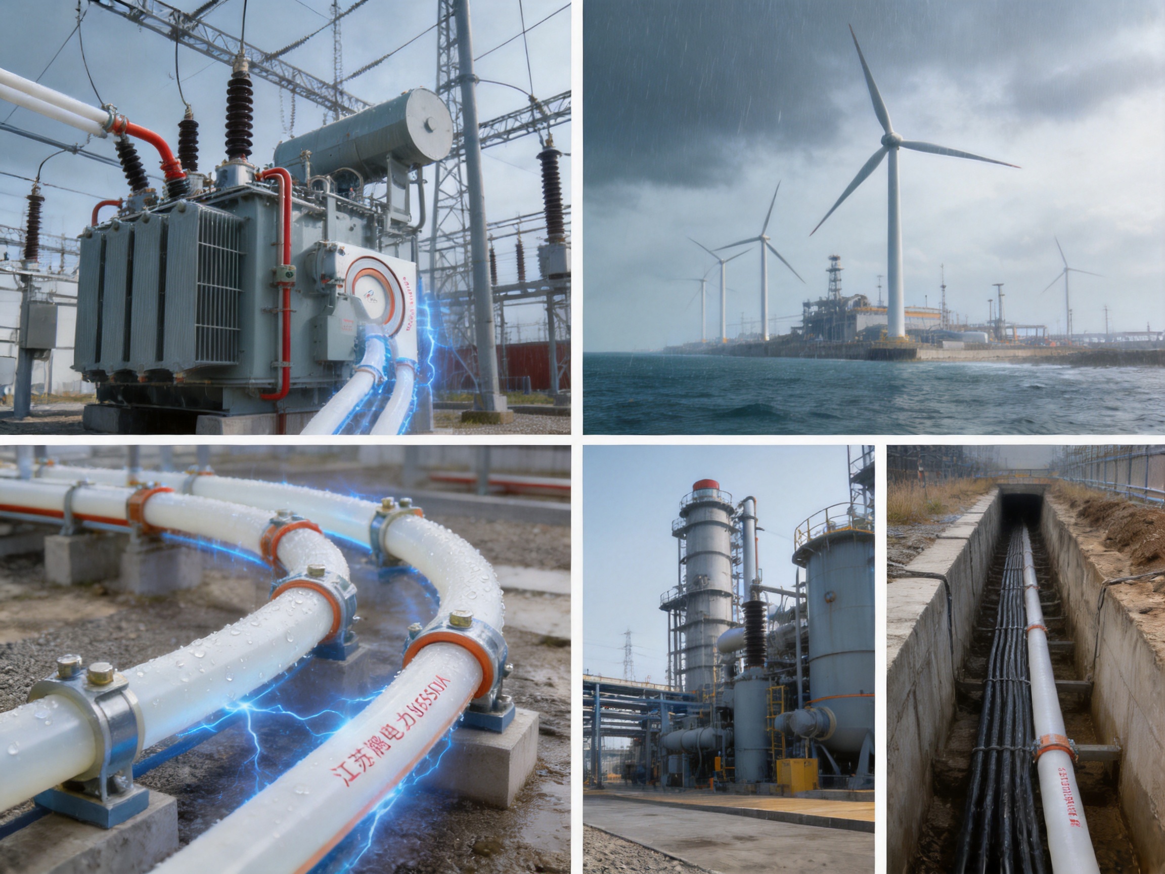
PTFE tubular bus bar is an advanced insulated conductor solution developed for power transmission systems that require high dielectric strength, reliable mechanical protection, resistance to chemical attack, and stable operation across a wide temperature range. Unlike conventional bare busbars or standard insulation systems, this design combines a copper or aluminum conductive core with a precision-wound polytetrafluoroethylene insulation structure, multiple capacitive screens, silicone rubber creepage extenders, and sealed protection against moisture and contamination.
The result is a compact and highly engineered busbar system suitable for demanding applications in substations, industrial plants, renewable-energy facilities, transportation infrastructure, large commercial buildings, and other installations where conventional cable or busbar arrangements may be difficult to install or maintain. The insulation system is designed to improve electric-field control, reduce the risk of surface discharge, enhance environmental resistance, and support long service life under severe operating conditions.
Jiangsu Wopeng Power Technology Co., Ltd. develops and manufactures insulated tubular busbar systems for medium- and low-voltage power distribution, as well as specialized applications requiring high-performance insulation. With experience in tubular busbars, epoxy-resin vacuum casting, copper and aluminum conductors, compact busbar systems, and sliding contact line systems, the company provides customized solutions for different current ratings, installation layouts, environmental conditions, and project requirements.
1. Overview of PTFE Tubular Bus Bar Technology
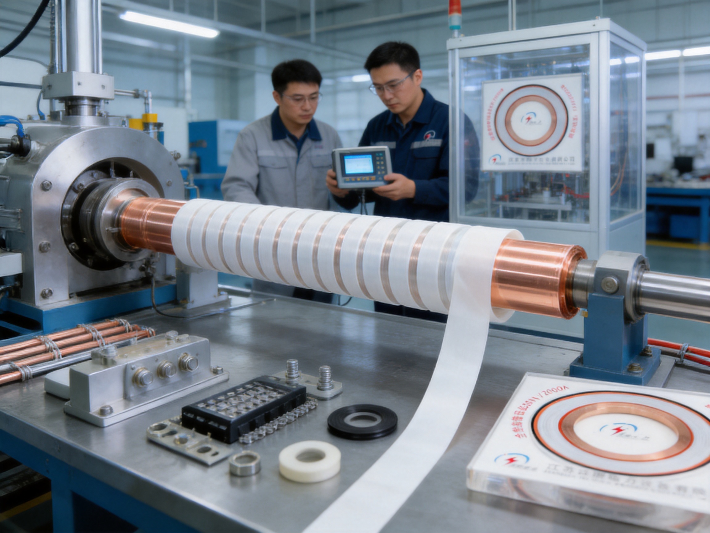
A PTFE tubular bus bar consists of a conductive metal tube or conductor core surrounded by a high-performance PTFE insulation system. Copper or aluminum may be selected according to conductivity requirements, weight limitations, short-circuit performance, and project economics. Around the conductor, PTFE film is wound under controlled mechanical tension to create a dense and continuous insulating layer.
PTFE, also known as polytetrafluoroethylene, is recognized for its low dielectric loss, high chemical inertness, low friction coefficient, non-stick surface, and broad thermal stability. These characteristics make it particularly useful when the busbar must operate in corrosive, humid, polluted, high-temperature, or low-temperature environments.
The insulation is not simply a loose wrapping around the conductor. The manufacturing process uses precise film winding, controlled inter-layer pressure, and specialized treatment methods to reduce air voids and maintain uniform insulation thickness. Silicone oil may be applied between PTFE layers to assist the formation of a dense, gas-free continuous insulating structure. This design helps minimize local electric-field concentration and supports stable dielectric performance.
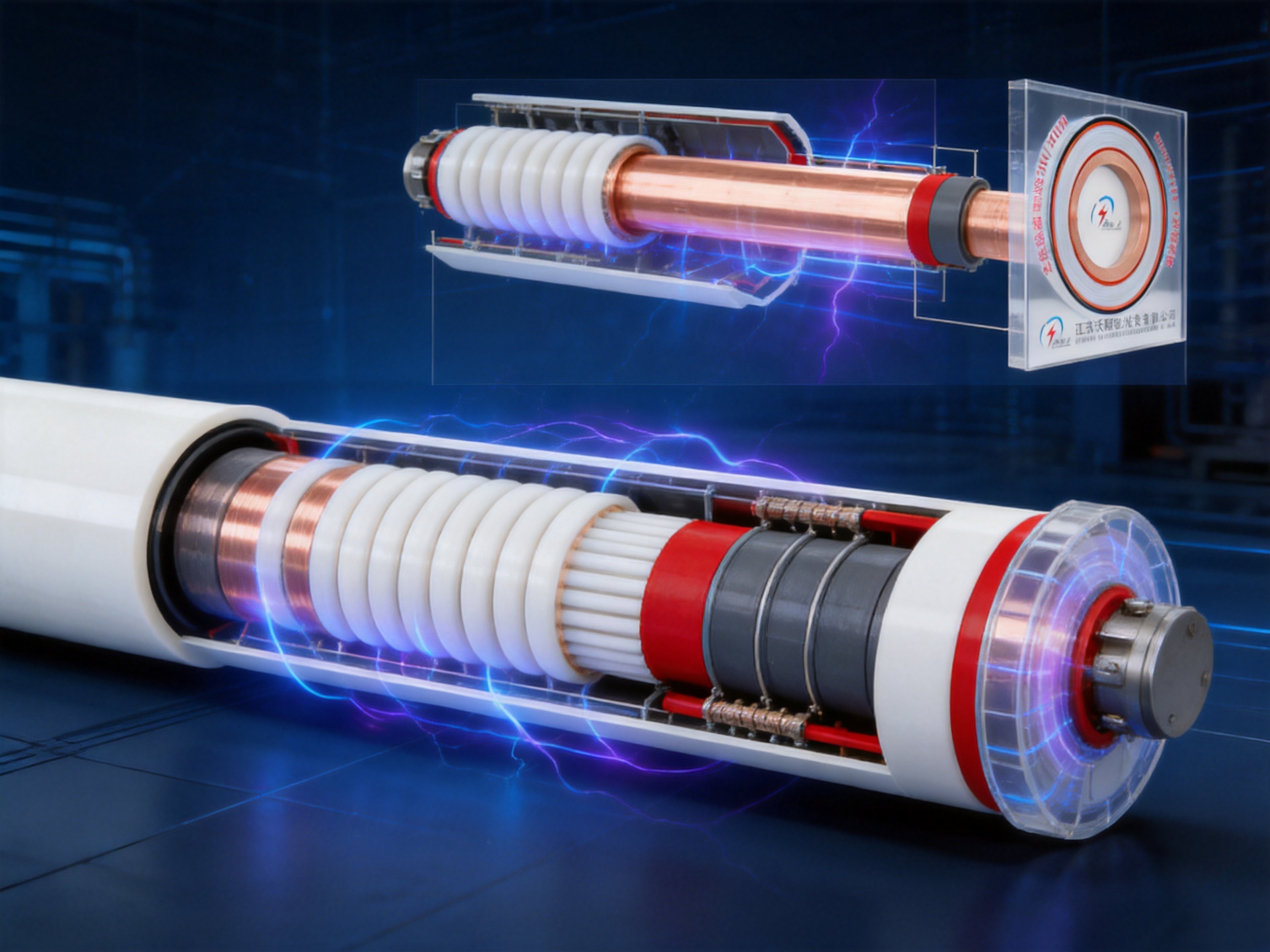
The product can incorporate at least five capacitive screens, including a zero screen, grading screen, and grounding screen. These layers help control the distribution of electrical stress from the conductor toward the grounded exterior. Silicone rubber creepage extenders can also be installed to increase the effective creepage distance and improve performance in environments exposed to moisture, dust, salt, or industrial contamination.
Depending on the selected configuration and validated operating conditions, the product is designed for a wide temperature range. The stated engineering range extends from approximately -60°C to 250°C for extreme-environment configurations, while other technical configurations may be specified for operation from -60°C to 200°C. Final limits should be confirmed according to conductor material, insulation structure, current loading, installation method, and project testing requirements.
The enclosure and sealing arrangement can provide protection up to IP68. This level of protection is valuable where the busbar may be exposed to water ingress, temporary immersion, condensation, dust, or difficult outdoor conditions. The sealed structure also reduces maintenance caused by contamination accumulation on exposed insulating surfaces.
2. Construction of the Insulated Tubular Busbar
2.1 Conductive Core
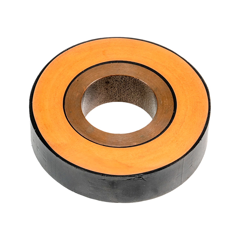
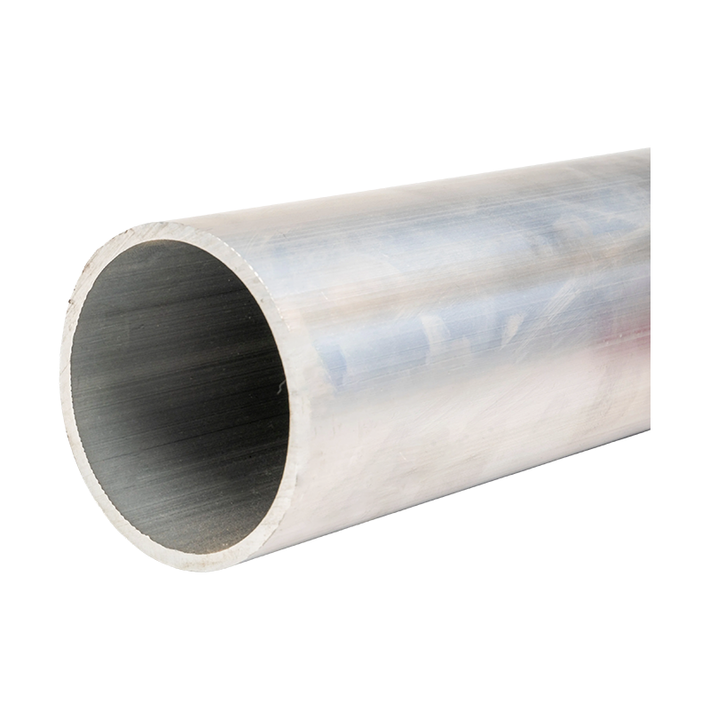
The conductive core is the primary current-carrying element. Copper offers high electrical conductivity and excellent short-circuit performance, while aluminum provides lower weight and can be advantageous for long spans, large cross-sections, and projects where transportation and installation efficiency are important.
The conductor dimensions are selected according to rated current, allowable temperature rise, short-circuit withstand requirements, voltage level, installation position, and available space. A tubular conductor can provide favorable mechanical rigidity compared with a flat conductor of similar current-carrying capability. This rigidity helps simplify support design and can improve alignment across longer installation sections.
Conductivity of the conductor core may reach or exceed 63% IACS, depending on the selected metal and product configuration. Electrical resistance, thermal rise, mechanical strength, and connection quality are evaluated during the engineering process to ensure that the final product matches the operating duty of the installation.
2.2 PTFE Insulation Layer
The primary insulation layer is formed by winding PTFE film around the conductor. A typical insulation thickness may be engineered within a range of approximately 4 to 8 mm, although actual thickness depends on voltage rating, dielectric coordination, environmental conditions, and customer specifications.
PTFE has a low dielectric constant and low dielectric loss compared with many traditional polymer insulation materials. These characteristics help reduce capacitive losses and support stable behavior during long-term operation. Its excellent resistance to acids, alkalis, salt spray, oils, and many organic solvents makes it suitable for coastal, chemical, industrial, and outdoor installations.
PTFE also has a very low coefficient of friction. This property can reduce mechanical stress during assembly and can be useful when the insulation system must accommodate controlled movement, thermal expansion, or installation through complex routes. However, the low surface energy of PTFE creates manufacturing challenges because ordinary adhesives do not bond easily to the material. Wopeng’s process therefore requires special surface treatment and controlled winding conditions to maintain layer stability.
2.3 Capacitive Screens and Electric-Field Control
High-voltage insulation must control more than simple physical contact between the conductor and the outside environment. Electrical stress is not always distributed evenly around a conductor, especially near joints, bends, terminals, supports, and changes in insulation geometry. Localized stress can produce partial discharge, accelerated aging, or insulation failure.
The PTFE tubular busbar uses multiple capacitive screens to manage this stress. The zero screen, grading screen, grounding screen, and other screen layers are arranged to provide a controlled electrical transition from the energized conductor to the grounded outer region. This arrangement helps reduce electric-field concentration and supports more predictable dielectric performance.
At connection points, the screen arrangement must be carefully coordinated with terminal geometry and grounding design. Incorrect screen termination can create a high-stress region even when the main straight section has excellent insulation. For this reason, engineering design, assembly accuracy, and routine electrical testing are all essential parts of the manufacturing process.
2.4 Silicone Rubber Creepage Extenders
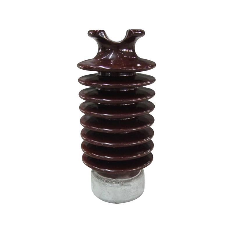
In polluted or humid environments, surface leakage may become a major concern. Dust, salt, moisture, and industrial deposits can create a conductive film over an insulating surface. Silicone rubber creepage extenders increase the surface distance available for leakage current and help interrupt continuous contamination paths.
Silicone rubber remains flexible across a broad temperature range and can maintain useful hydrophobic properties. When combined with the PTFE insulation system, it improves the busbar’s ability to operate in areas where airborne contamination or condensation may otherwise reduce insulation reliability.
2.5 Sealing and Protection
A sealed tubular busbar reduces exposure of the insulation system to water, dust, insects, chemical vapors, and accidental contact. A protection rating reaching IP68 provides a significant advantage over open busbars and partially protected conductor arrangements.
Sealing performance depends on the complete system, including end caps, joints, terminals, flexible connections, support interfaces, and cable entry components. Therefore, the complete assembly must be designed and tested as a system rather than evaluated only by examining the straight busbar section.
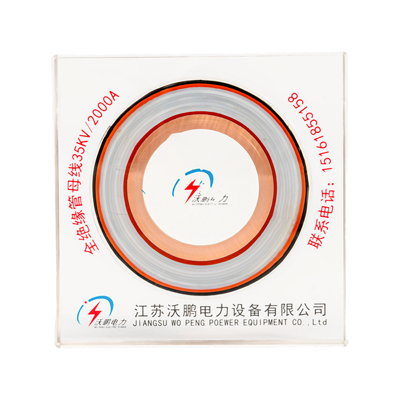
PTFE Tubular Bus Bar
3. Main Technical Advantages
3.1 Wide Temperature Capability
One of the most important advantages of PTFE tubular bus bar is its ability to tolerate demanding temperature conditions. The material is suitable for cold outdoor regions, hot industrial zones, high-temperature equipment rooms, and installations subject to rapid temperature changes.
The stated operating range can extend from -60°C to 250°C for specially designed configurations. This broad range provides greater design flexibility than many epoxy-resin and silicone-rubber insulation systems, whose practical operating ranges are often narrower. In cold climates, the insulation remains suitable for applications exposed to low ambient temperatures. In hot areas, PTFE maintains stable dielectric properties when the conductor temperature is properly controlled.
Thermal performance must always be considered together with current loading and heat dissipation. A high-temperature insulation material does not eliminate the need to calculate conductor temperature rise, ventilation, support spacing, and terminal heating. Wopeng’s engineering process considers these factors when selecting the conductor and defining the insulation system.
3.2 High Dielectric Strength
The dielectric strength of the PTFE insulation structure can reach or exceed 35 kV/mm under specified test conditions. This provides a strong electrical margin for medium- and high-voltage applications when the insulation thickness, screening structure, and termination design are correctly coordinated.
High dielectric strength helps prevent leakage, flashover, and internal breakdown. It is especially important in compact installations where electrical clearances are limited and the busbar must carry high energy within a controlled physical envelope.
The use of multiple capacitive screens further improves the practical performance of the insulation system by reducing uneven electric-field stress. The combination of material strength, controlled winding, screen design, and testing is more important than any single material specification.
3.3 Corrosion and Chemical Resistance
PTFE is chemically inert to many acids, alkalis, salt solutions, and organic solvents. This resistance makes PTFE tubular busbar suitable for coastal substations, chemical-processing plants, wastewater facilities, industrial production lines, and other locations where conventional insulation may deteriorate more quickly.
Corrosion resistance also reduces the risk of surface degradation caused by cleaning agents, airborne chemicals, or salt spray. The busbar can therefore provide a longer maintenance interval when the installation is designed and installed correctly.
3.4 Low Dielectric Loss
PTFE has a low dielectric constant and low dielectric loss. A dielectric loss factor of approximately 0.0002 at 50 Hz may be achieved under specified conditions. Low dielectric loss helps reduce energy dissipation within the insulation and supports stable operation in long or electrically demanding busbar sections.
Lower dielectric loss can also reduce thermal stress in the insulation system. Although conductor losses generally dominate the total power loss of a busbar, maintaining low dielectric loss is valuable in high-voltage systems where insulation behavior contributes to overall efficiency and long-term reliability.
3.5 Low Friction and Mechanical Flexibility
The low friction coefficient of PTFE can reduce mechanical resistance during controlled assembly and movement. This is beneficial when the busbar must be installed through a cable trench, cable mezzanine, equipment room, or a route containing multiple alignment points.
Thermal expansion, vibration, and small installation tolerances can create mechanical stress in rigid electrical systems. A carefully engineered PTFE layer can help accommodate limited movement without compromising the main insulation system. The design must still include suitable supports, expansion provisions, and connection components.
3.6 Sealed Environmental Protection
Conventional open busbars can be vulnerable to accidental contact, dust accumulation, condensation, and foreign objects. A fully insulated tubular busbar provides a safer and cleaner arrangement by enclosing the energized conductor within a controlled insulation system.
With protection up to IP68, the product is suitable for installations where water and dust protection are important. This can reduce cleaning requirements and lower the risk of contamination-related flashover. It also allows engineers to consider installation routes that would be unsuitable for exposed conductors.
4. Comparison with Other Insulated Busbar Technologies
PTFE tubular busbar competes with epoxy-resin cast busbars, silicone-rubber insulated busbars, conventional insulated cables, and bare or semi-insulated busbars. Each technology has appropriate applications, but PTFE provides a distinctive combination of thermal range, chemical resistance, dielectric performance, and low-loss operation.
| Busbar Type | Typical Breakdown Strength | Typical Temperature Range | Dielectric Loss | Environmental Resistance |
|---|---|---|---|---|
| PTFE tubular busbar | At least 35 kV/mm under specified conditions | Approximately -60°C to 200°C or up to 250°C for selected configurations | Approximately 0.0002 at 50 Hz | Excellent chemical, moisture, salt-spray, and temperature resistance |
| Epoxy-resin cast busbar | Approximately 30 kV/mm | Approximately -30°C to 130°C | Approximately 0.001 | Good rigidity and insulation, but more sensitive to thermal shock and certain environmental conditions |
| Silicone-rubber insulated busbar | Approximately 25 kV/mm | Approximately -40°C to 120°C | Approximately 0.0005 | Good flexibility and weather resistance, with lower dielectric and thermal margins in some applications |
| Bare busbar | Dependent on air clearance and support design | Dependent on conductor and environment | Very low insulation loss because there is no primary insulation | Requires greater clearance and protection against contamination, contact, and short circuit |
The comparison should not be interpreted as a universal replacement statement. Epoxy-resin cast busbars may be highly effective for standard indoor medium-voltage applications, especially where high rigidity and compact dimensions are required. Silicone rubber may be preferred where flexibility and outdoor weathering are central requirements. Bare busbars can remain economical in controlled substations with sufficient clearance.
PTFE tubular busbar becomes particularly attractive when the project requires a broad operating-temperature range, strong corrosion resistance, low dielectric loss, high moisture protection, or a compact fully insulated route. Its higher material and manufacturing cost can be justified where reduced maintenance, improved environmental protection, and long-term reliability are more important than the lowest initial purchase price.
5. Manufacturing Process and Quality Control
5.1 Engineering Design and Product Customization
Manufacturing begins with a technical review of the customer’s electrical and mechanical requirements. Important parameters include rated voltage, rated current, conductor material, conductor dimensions, short-circuit current, route length, support spacing, bend requirements, terminal arrangement, ambient temperature, pollution level, moisture exposure, and required protection rating.
A custom PTFE tubular busbar manufacturer must also review the installation environment. A busbar located inside a controlled electrical room may require a different insulation and sealing arrangement from one installed in a coastal substation, chemical plant, wind turbine, or underground cable trench.
Wopeng’s engineering team can develop solutions according to the specific project layout. This may include straight sections, elbows, expansion sections, flexible connections, terminal interfaces, grounding arrangements, support hardware, and integration with switchgear or transformer terminals.
5.2 Conductor Preparation
The copper or aluminum conductor is prepared using controlled cutting, forming, machining, and surface-cleaning procedures. Dimensional accuracy is important because the conductor affects insulation thickness, electric-field distribution, joint alignment, and terminal installation.
CNC machining equipment can be used to produce accurate conductor interfaces and connection components. Machined surfaces must be free of burrs, sharp edges, oil contamination, and irregularities that could damage the PTFE film or create local electrical stress.
Before insulation winding, the conductor is inspected for dimensional conformity and surface quality. Any deviation that could affect concentricity or insulation uniformity must be corrected before the next production stage.
5.3 Precision PTFE Film Winding
The PTFE film-winding process is one of the most technically demanding stages. The film must be applied with consistent overlap, stable tension, accurate positioning, and controlled compression. Inter-layer tension uniformity may need to be controlled within approximately ±2 percent.
Uneven tension can create several problems. Excessive tension may damage the film or produce local thinning, while insufficient tension may leave gaps or allow movement between layers. Inconsistent overlap can generate weak regions in the insulation. The winding equipment and operating parameters must therefore be monitored continuously.
Ultrasonic assistance may be used to help control trapped bubbles and improve the continuity of the insulation. The objective is to create a dense, gas-free structure with minimal voids. Voids are undesirable because they can intensify electric-field stress and contribute to partial discharge under high voltage.
5.4 Inter-Layer Treatment and Adhesion Control
PTFE has a low surface energy, which makes direct bonding between layers difficult. Special treatment agents and surface-processing methods are therefore used to improve inter-layer stability. The treatment must be carefully controlled so that it does not compromise the chemical resistance or dielectric performance of the finished insulation.
Adhesion control is especially important at transitions, joints, terminals, and areas exposed to vibration or thermal cycling. The manufacturing process must ensure that the layers remain correctly positioned throughout the service life of the product.
5.5 Installation of Capacitive Screens
Capacitive screens are installed according to the designed electrical-field structure. Screen positioning, overlap, grounding continuity, and termination geometry are verified during assembly. A small dimensional error in a screen can alter the local electrical stress distribution.
The zero screen, grading screen, and grounding screen are integrated with the insulation and terminal system. The complete arrangement is checked for electrical continuity, insulation coordination, and compatibility with the customer’s grounding design.
5.6 Silicone Rubber Creepage Components
Silicone rubber creepage extenders are installed at locations where surface leakage performance is important. Their dimensions, spacing, adhesion, and mechanical security are inspected. The components must remain stable during transportation, installation, thermal cycling, and long-term exposure to the environment.
5.7 Sealing, Assembly, and Final Finishing
After the main insulation and screens are completed, the busbar is assembled with end fittings, connection components, support interfaces, seals, and protective elements. Particular attention is given to the transition between the insulated tube and the terminal because this region experiences combined electrical, mechanical, and environmental stress.
Sealing operations are performed to achieve the required protection rating. The finished assembly is checked for surface defects, dimensional accuracy, concentricity, terminal alignment, screen continuity, and mechanical integrity.
5.8 Testing and Inspection
Quality control includes standardized inspection procedures such as high-voltage testing, insulation-resistance testing, mechanical verification, dimensional inspection, and routine production checks. Depending on the project, additional tests may include partial-discharge evaluation, temperature-rise testing, water-ingress testing, salt-spray assessment, thermal cycling, and short-circuit withstand verification.
Wopeng also works with third-party testing institutions when independent validation is required. This provides additional confidence for major infrastructure projects, utility installations, renewable-energy facilities, and other applications with demanding approval procedures.
6. Manufacturing Strengths of Jiangsu Wopeng Power Technology
Jiangsu Wopeng Power Technology Co., Ltd. was founded in 2018 as a specialized high-tech enterprise focused on high- and low-voltage busbar systems. The company combines product development, engineering design, manufacturing, testing, and project support within one organization.
Its product portfolio includes 35 kV epoxy-resin vacuum-cast tubular busbars, low-voltage cast-resin busways, copper and aluminum tubular busbars, wind-power tubular busbars, compact busbar systems, and sliding contact line power supply systems. This broad product range gives the engineering team practical experience across different conductor structures, insulation systems, voltage classes, and installation environments.
The company operates modern production lines equipped with vacuum-casting systems, CNC machining equipment, and automated assembly technologies. These capabilities support repeatable production and help reduce variation between individual busbar sections.
Vacuum-casting experience is particularly valuable because it develops expertise in void control, resin processing, insulation coordination, and high-voltage quality management. Although PTFE tubular busbar uses a different insulation process, the same principles of material preparation, process control, dimensional accuracy, and electrical testing remain important.
CNC machining equipment supports accurate production of conductors, terminals, connectors, and mechanical interfaces. Automated assembly technologies improve consistency during repetitive operations and help maintain controlled positioning of insulation components and screens.
The company’s quality management approach includes process inspection and final product verification. Each product is evaluated through appropriate high-voltage, insulation, mechanical, and routine quality checks. Testing collaboration with independent institutions provides additional technical support for project-specific verification.
Wopeng products operate across more than 17 provinces and serve industries including power generation, substations, wind energy, industrial manufacturing, rail transit, and large commercial facilities. This operating experience enables the company to understand practical installation conditions rather than relying only on laboratory performance.
The company provides OEM and customized manufacturing services. Customers can request specific conductor materials, insulation thicknesses, busbar lengths, terminal structures, support arrangements, screen configurations, and environmental protection levels. Customization is particularly useful when the busbar must connect directly with existing transformers, switchgear, generators, or specialized electrical equipment.
7. Application Solutions
7.1 Transformer-to-Switchgear Connections
One of the most common applications is the direct connection between the low-voltage terminals of a main transformer and the terminals of a switch cabinet. This arrangement is suitable for high-current transmission and can provide a clean, organized route between major electrical equipment.
A fully insulated tubular busbar can reduce the need for large air clearances and provide greater protection against accidental contact and contamination. The connection may be designed as a straight route or may include bends and transition sections according to the equipment layout.
7.2 Cable Trenches and Cable Mezzanines
Tubular busbars can be routed through underground cable trenches or cable mezzanines. This method is useful when direct overhead routing is impractical or when the project requires a protected connection between switch cabinets.
The fully insulated structure helps protect the conductor from moisture, dust, and mechanical interference. It also provides a more organized alternative to multiple parallel cables in locations where space is limited or cable routing is complicated.
7.3 Switchgear Interconnections
PTFE tubular busbar can be used for connections between switch cabinets, distribution sections, and other high-current equipment. The system can be designed with customized terminal positions and support structures to match the switchgear arrangement.
Correct phase spacing, screen grounding, expansion allowance, and access for inspection must be considered during design. Factory-assembled sections can reduce field installation time and improve alignment accuracy.
7.4 Wind Power and Renewable-Energy Facilities
Wind turbines and renewable-energy facilities may expose electrical equipment to vibration, temperature variation, humidity, salt spray, and difficult maintenance conditions. Tubular busbars can provide a compact and protected connection between generators, transformers, converters, and switchgear.
In wind-power applications, mechanical design is as important as electrical performance. The busbar must be able to accommodate vibration and thermal movement while maintaining secure connections. PTFE’s low friction and broad temperature capability can support this type of application when combined with suitable mechanical supports.
7.5 Industrial and Chemical Facilities
Chemical plants, metal-processing facilities, wastewater-treatment sites, and other industrial environments may contain corrosive vapors, cleaning chemicals, salt deposits, or conductive dust. PTFE’s chemical resistance provides an advantage in these conditions.
The sealed design can also reduce maintenance caused by contamination. However, the complete installation must still be inspected periodically, especially at joints, terminals, grounding points, and support components.
7.6 Rail Transit and Large Commercial Buildings
Rail transit systems and large commercial facilities often require compact, reliable, and well-organized power distribution. Tubular busbar systems can support high-current connections in substations, equipment rooms, distribution corridors, and other areas where space and safety are important.
The fully insulated construction can improve personnel protection and reduce the risk associated with exposed conductors. Factory-engineered sections can also simplify coordination with architectural structures and existing electrical equipment.
7.7 Intelligent Monitoring Systems
Wopeng has developed a tubular busbar monitoring system for unmanned intelligent supervision of multiple technical parameters. Depending on the project configuration, monitoring may be used to support condition assessment, operating-data collection, fault indication, and maintenance planning.
Digital monitoring can help operators identify abnormal temperature, insulation behavior, or other changes before they develop into serious failures. The monitoring architecture should be selected according to the customer’s protection system, communication requirements, and maintenance strategy.
8. Design Considerations for Project Engineers
8.1 Voltage and Insulation Coordination
Selection begins with the system voltage and required insulation level. The designer must consider operating voltage, lightning impulse withstand, switching surges, pollution level, altitude, clearances, creepage distance, and connection geometry.
Although PTFE insulation may provide high dielectric strength, the final voltage rating depends on the complete busbar assembly. Straight sections, joints, terminals, screens, supports, and adjacent equipment must all be included in the insulation-coordination review.
8.2 Current Rating and Thermal Rise
Rated current is determined by conductor size, conductor material, allowable temperature rise, ambient temperature, installation orientation, ventilation, and duty cycle. The project designer should provide both continuous current and short-time overload information.
Aluminum conductors may reduce system weight, while copper conductors may provide higher conductivity in a smaller cross-section. The appropriate selection depends on the balance between space, weight, current, mechanical strength, and budget.
8.3 Short-Circuit Withstand
Short-circuit forces can be substantial, especially in transformer-to-switchgear connections. The busbar, joints, supports, and terminals must be evaluated for thermal and mechanical short-circuit withstand.
Support spacing and connection hardware have a direct effect on mechanical performance. A robust insulation system cannot compensate for inadequate support design. Wopeng’s engineering process therefore considers electrical and mechanical performance together.
8.4 Environmental Conditions
Project specifications should identify the expected ambient temperature, humidity, altitude, salt exposure, chemical contamination, dust, vibration, water exposure, and ultraviolet radiation. These factors influence the insulation thickness, creepage arrangement, sealing design, support materials, and testing program.
For coastal or polluted environments, silicone rubber creepage extenders and sealed protection may be especially valuable. For low-temperature sites, the mechanical behavior of seals, supports, and connection components should also be confirmed.
8.5 Installation and Maintenance Access
The route should be reviewed before production begins. Engineers should confirm the available space, lifting points, bend radius, equipment interfaces, support locations, access for tightening connections, and provisions for future inspection.
Factory prefabrication can reduce field work, but accurate site measurements are essential. Incorrect dimensions at the transformer or switchgear interface may lead to installation delays. Customized drawings and interface reviews help minimize this risk.
9. Advantages Over Conventional Solutions
Compared with bare busbars, PTFE tubular busbars offer substantially improved protection against accidental contact, dust, moisture, and contamination. They can reduce the required clearance in certain layouts and provide a cleaner appearance in equipment rooms and industrial facilities.
Compared with conventional cables, tubular busbars can offer higher mechanical rigidity, more predictable geometry, and easier arrangement for high-current connections. They may also simplify the organization of multiple phases and reduce the complexity of large cable bundles.
Compared with epoxy-resin cast busbars, PTFE offers a wider temperature range, lower dielectric loss, superior chemical resistance, and stronger adaptability to extreme environments. Epoxy systems may still be more economical for standard indoor installations, but PTFE is better suited to projects where environmental severity is a major concern.
Compared with silicone-rubber insulation, PTFE can provide higher dielectric strength and a broader temperature capability in the specified designs. Silicone rubber remains useful for flexible sections and outdoor applications, and it is also used in PTFE systems as a creepage-extending component.
The main disadvantage is cost. PTFE material is more expensive than many conventional insulation materials, and its low surface energy makes processing more difficult. Precision winding, special surface treatment, bubble control, and inspection add to the manufacturing requirements. For this reason, PTFE tubular busbar should be selected based on lifecycle value rather than initial purchase cost alone.
10. Service Life and Reliability
Under normal high-voltage operating conditions and with correct installation, the expected service life of a PTFE tubular busbar may reach approximately 35 to 45 years. Actual service life depends on voltage stress, conductor temperature, thermal cycling, mechanical vibration, environmental contamination, joint quality, and maintenance practices.
Long service life begins with consistent manufacturing. Uniform insulation thickness, controlled film tension, effective void reduction, secure layer adhesion, accurate screen installation, and reliable sealing all contribute to long-term performance.
Routine maintenance should include visual inspection of supports, terminals, seals, grounding connections, and monitoring devices. Inspection intervals should be based on the importance of the installation and the severity of the environment. In critical systems, periodic insulation testing and thermal imaging may be recommended.
Although PTFE is difficult to degrade and recycle, responsible product management should include appropriate end-of-life handling. Conductors can often be separated for metal recovery, while the PTFE insulation requires specialized processing. Project owners should consider disposal and recycling requirements during procurement and lifecycle planning.
11. Frequently Asked Questions
Q1: What is a PTFE tubular bus bar?
A PTFE tubular bus bar is a conductive copper or aluminum core surrounded by a precision-engineered PTFE insulation system. It may also include capacitive screens, grounding layers, silicone rubber creepage extenders, sealed terminals, and protective components.
Q2: What voltage range can it support?
The suitable voltage range depends on the conductor, insulation thickness, screen structure, terminal design, and testing requirements. The product is intended for demanding medium- and high-voltage applications, and customized solutions may be engineered for systems from medium voltage to higher voltage levels. Final ratings must be confirmed through project-specific electrical design and testing.
Q3: What temperature range is available?
Selected configurations are designed for operation from approximately -60°C to 250°C. Other configurations may be specified from -60°C to 200°C. The final operating temperature depends on the conductor, current loading, installation environment, and validated product design.
Q4: Is PTFE tubular busbar suitable for outdoor use?
Yes. Its chemical resistance, temperature tolerance, sealed structure, and potential IP68 protection make it suitable for many outdoor applications. Outdoor projects must still evaluate ultraviolet exposure, rain, snow, wind, pollution, support design, and terminal protection.
Q5: Can the busbar be customized?
Yes. A custom PTFE tubular busbar can be designed with specified conductor material, conductor dimensions, insulation thickness, busbar length, terminal configuration, screen arrangement, bend geometry, support interfaces, and monitoring functions.
Q6: How does PTFE compare with epoxy-resin insulation?
PTFE generally offers a wider temperature range, stronger chemical resistance, lower dielectric loss, and high dielectric strength. Epoxy resin may provide a lower-cost solution with high rigidity for standard indoor applications. The best choice depends on environmental severity, voltage, current, space, budget, and lifecycle requirements.
Q7: Why are capacitive screens necessary?
Capacitive screens help control the electric-field distribution between the energized conductor and the grounded exterior. They reduce local electrical stress and improve insulation coordination, particularly around high-voltage sections and terminations.
Q8: What information is needed for a quotation?
Important information includes system voltage, rated current, conductor preference, short-circuit level, busbar length, route drawings, terminal dimensions, environmental conditions, protection rating, installation method, quantity, and required inspection or certification documents.
Q9: How is the product tested?
Testing may include high-voltage tests, insulation-resistance tests, dimensional inspection, mechanical verification, screen-continuity checks, temperature-rise testing, sealing tests, and other project-specific evaluations. Independent third-party testing can also be arranged when required.
Q10: What is the expected service life?
Under suitable operating conditions, correct installation, and proper maintenance, the expected service life may reach approximately 35 to 45 years. Environmental and electrical stress should be reviewed when establishing the final service-life expectation.
Q11: Is PTFE difficult to manufacture?
Yes. PTFE has low surface energy, which creates inter-layer adhesion challenges. The winding process also requires accurate tension control, consistent overlap, and bubble reduction. These requirements make process discipline and specialized equipment essential.
Q12: Why choose a specialized manufacturer?
A specialized manufacturer can coordinate conductor design, insulation engineering, screening, terminals, supports, testing, and installation interfaces as one complete system. This reduces the risk of incompatibility between separately sourced components and supports reliable project implementation.
12. Why Select an Experienced OEM Manufacturer
PTFE tubular busbar is not a simple standard component. Its performance depends on the relationship between material selection, conductor dimensions, insulation thickness, winding accuracy, screen design, terminal construction, sealing, and site installation. An experienced OEM manufacturer can manage these variables from the initial engineering review through final inspection.
Jiangsu Wopeng Power Technology combines specialized busbar manufacturing with project-based engineering support. The company’s experience with epoxy-resin cast tubular busbars, low-voltage busways, copper and aluminum tubular conductors, wind-power systems, compact busbars, and sliding contact lines provides a broad technical foundation.
The company’s modern production equipment, including vacuum-casting systems, CNC machining equipment, and automated assembly technologies, supports high manufacturing consistency. Standardized inspection processes and cooperation with third-party testing organizations further strengthen quality assurance.
For customers, this means the supply process can include technical consultation, customized design, production, testing, documentation, and application support. The objective is not only to deliver an insulated conductor, but to provide a complete tubular busbar system that integrates safely with the surrounding electrical installation.
13. Conclusion
PTFE tubular bus bar is a high-performance solution for power transmission where standard insulation systems may not provide sufficient environmental, thermal, or dielectric performance. Its precision-wound PTFE insulation, multiple capacitive screens, silicone rubber creepage extenders, low dielectric loss, strong chemical resistance, broad temperature capability, and potential IP68 protection make it suitable for demanding electrical installations.
The technology provides meaningful advantages over bare busbars, conventional cables, epoxy-resin cast busbars, and standard silicone-rubber systems when extreme temperature, corrosive contamination, moisture, compact routing, or high insulation performance is required.
Its higher cost and more complex manufacturing process require careful engineering and professional production control. Uniform winding tension, bubble reduction, inter-layer treatment, screen accuracy, sealing integrity, and comprehensive testing are essential to achieving reliable service.
With advanced production equipment, experienced engineering personnel, customized OEM capabilities, and a wide portfolio of busbar technologies, Jiangsu Wopeng Power Technology is positioned to support projects requiring reliable insulated tubular busbar systems. Through correct specification, controlled manufacturing, and proper installation, PTFE tubular busbar can provide safe and efficient power transmission over a long operating life.
References
1. IEC 61439, Low-Voltage Switchgear and Controlgear Assemblies, applicable design and verification principles.
2. IEC 60071, Insulation Coordination, principles for electrical clearances and withstand requirements.
3. IEC 60270, High-Voltage Test Techniques, Partial Discharge Measurements.
4. IEC 60060, High-Voltage Test Techniques.
5. ASTM D149, Standard Test Method for Dielectric Breakdown Voltage and Dielectric Strength of Solid Electrical Insulating Materials.
6. ASTM D257, Standard Test Methods for DC Resistance or Conductance of Insulating Materials.
7. Technical data and product engineering information for PTFE insulated tubular busbar systems.
8. Technical information concerning copper and aluminum tubular conductors, capacitive screens, creepage extenders, and sealed busbar assemblies.
Product: PTFE Tubular Bus Bar




-
 +86-180 3625 3000
-
 admin@wpbusbar.com
-
 No. 8, Yanjin Road, Chengxi Industrial Park, Shanyang Town, Baoying County, Yangzhou City, Jiangsu Province, China
Copyright © Jiangsu Wopeng Power Technology Co., Ltd.
All Rights Reserved.
 Custom Insulated Bus Bar Manufacturer
Tubular Busbar System Factory
Custom Insulated Bus Bar Manufacturer
Tubular Busbar System Factory