

 EN
EN

 English
 русский
 Français
 Español
 عربى
عربى


Fixed Bus-Bar Supports for Reliable Tubular Busbar Systems
Content
- 1 1. The Role of Fixed Bus-Bar Supports in Electrical Systems
- 2 2. Product Scope and Related Hardware
- 3 3. Materials Used in Bus-Bar Support Construction
- 4 4. Technical Advantages of the Fixed Support Type
- 5 5. Manufacturing Processes and Quality Control
- 6 6. Advantages Over General-Purpose Competitor Products
- 7 7. Applications in Power Distribution and Infrastructure
- 8 8. Selecting the Correct Fixed Bus-Bar Support
- 9 9. Installation and Maintenance Recommendations
- 10 10. Manufacturing Strengths and Customization Capability
- 11 11. Why System-Level Quality Matters
- 12 12. Frequently Asked Questions
- 12.1 Q1: What is a fixed bus-bar support?
- 12.2 Q2: What tubular busbar diameters are supported by Type MGG fixed hardware?
- 12.3 Q3: When should a reinforced fixed support be used?
- 12.4 Q4: Are fixed bus-bar supports suitable for both low-voltage and medium-voltage systems?
- 12.5 Q5: What materials are commonly used for insulated bus-bar supports?
- 12.6 Q6: How does hot-dip galvanizing improve support performance?
- 12.7 Q7: What is the purpose of an MGF end cap?
- 12.8 Q8: How should support spacing be determined?
- 12.9 Q9: Can bus-bar supports be customized for OEM projects?
- 12.10 Q10: What inspections should be completed before energizing a busbar system?
- 12.11 Q11: How can overheating at a support or connection be prevented?
- 12.12 Q12: Why is a specialized manufacturer preferable to a general hardware supplier?
- 13 13. Conclusion
- 14 References
- 15 Product: Bus-bar Supports (Fixed Support Type)
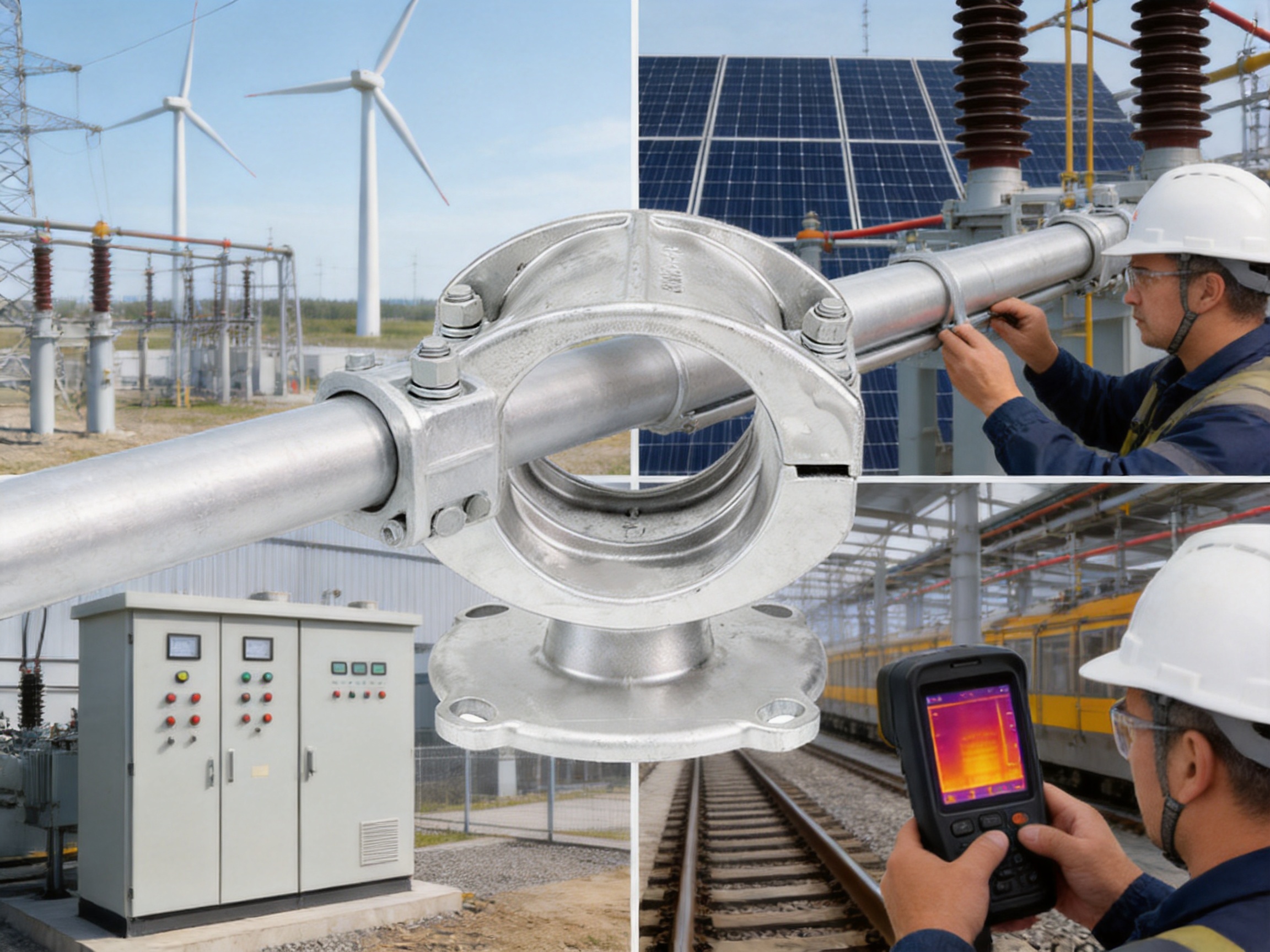
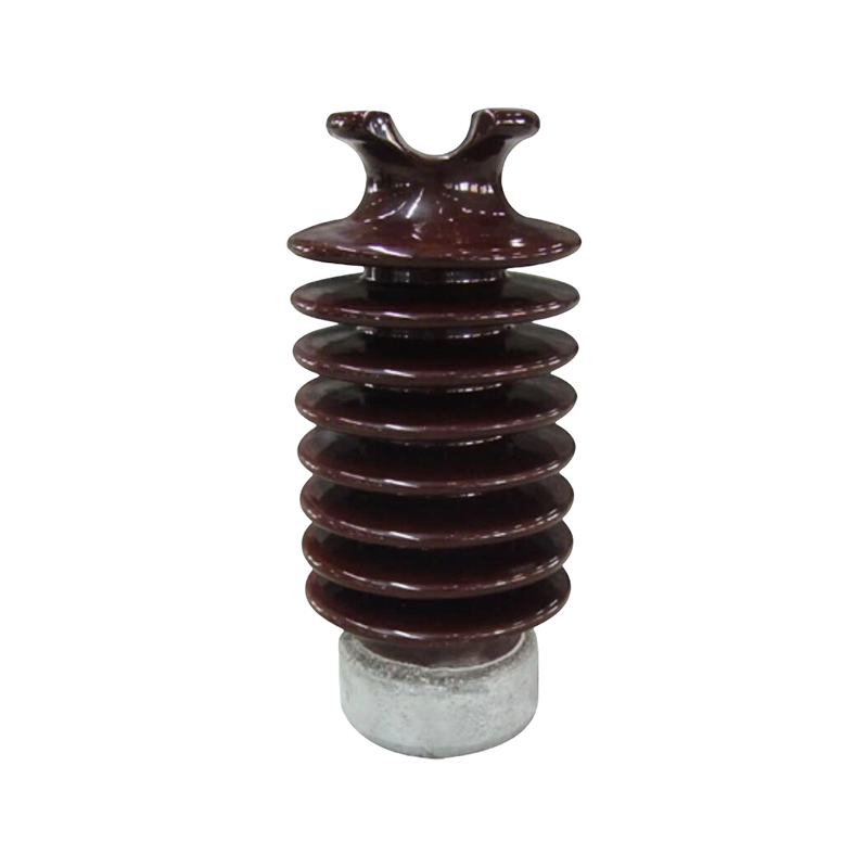
Bus-bar supports are essential mechanical and insulating components in modern electrical distribution systems. They hold busbars in their designed position, maintain electrical clearances, control vibration, and help the complete assembly withstand the powerful electrodynamic forces generated during short-circuit conditions. Although they are relatively compact compared with a complete busbar system, their design and manufacturing quality directly affect safety, service life, maintenance requirements, and operating reliability.
The fixed support type is especially important in tubular busbar installations. It provides a stable mounting point for aluminum alloy tubular busbars, copper tubular busbars, and other rigid conductors used in medium- and low-voltage applications. A correctly selected fixed support prevents unwanted movement while allowing the busbar system to maintain its intended alignment under thermal expansion, vibration, wind loading, and fault-current stress.
Jiangsu Wopeng Power Technology Co., Ltd. develops and manufactures busbar systems and related hardware for demanding power transmission and distribution applications. Its product portfolio includes fixed hardware for tubular busbars, end caps, tension clamps, steel-cored aluminum strand supports, insulated busbars, epoxy resin cast busbars, compact busbar systems, and sliding contact line systems. Through engineering design, controlled production, standardized inspection, and application-specific customization, the company provides support solutions for substations, industrial facilities, renewable energy installations, rail transit systems, and large commercial projects.
1. The Role of Fixed Bus-Bar Supports in Electrical Systems
A busbar carries a large amount of electrical current through a switchgear assembly, distribution cabinet, substation, transformer connection, wind power installation, or industrial power network. Because the conductor must remain electrically isolated from the enclosure and adjacent phases, it cannot simply be placed on a metal frame. It requires a support system that combines mechanical strength with reliable insulation and dimensional accuracy.
Fixed bus-bar supports are designed to secure the conductor at predetermined points. They maintain the distance between phases, preserve the clearance between the busbar and the grounded structure, and prevent sagging or lateral displacement. In tubular busbar systems, the support usually interfaces with the outside diameter of the tube and transfers mechanical loads into the supporting structure.
During normal operation, the support must withstand the weight of the conductor, connection hardware, thermal expansion effects, vibration, and installation loads. During a short circuit, the electromagnetic forces may increase dramatically. Adjacent conductors carrying fault current can attract or repel one another, creating sudden mechanical stress. A support with insufficient strength, poor clamping geometry, or inadequate fastening can allow movement, deformation, cracking, or loss of phase clearance.
For this reason, the support should be treated as a key part of the busbar system rather than as a simple accessory. Its material, surface finish, dimensions, fasteners, contact pressure, insulation properties, and installation method all contribute to the safety of the complete assembly.
1.1 Mechanical Fixation
The main function of a fixed support is to hold the tubular busbar securely. The support must provide sufficient clamping force without damaging the conductor surface. Excessive pressure may deform a thin-walled aluminum tube, while insufficient pressure may allow slipping or vibration. The geometry is therefore designed to distribute the load across the contact area and maintain stability over the expected operating period.
Fixed supports are commonly installed at regular intervals along a busbar route. The spacing depends on conductor size, current rating, installation orientation, span length, fault-current level, environmental conditions, and the mechanical data of the support. Heavier conductors and systems exposed to high short-circuit forces normally require closer spacing or reinforced support arrangements.
1.2 Electrical Insulation and Clearance Control
Bus-bar supports also help maintain the electrical separation required by the system design. An insulating support separates the energized conductor from the grounded mounting frame. It can also preserve the phase-to-phase distance between multiple conductors. Stable spacing is essential because a reduction in clearance may increase the risk of flashover, tracking, partial discharge, or accidental contact.
For medium-voltage applications, the support design must consider electric-field distribution, surface contamination, humidity, and the possibility of corona activity. Smooth surfaces, rounded profiles, suitable creepage distances, and appropriate insulating materials help reduce local electric-field concentration. In low-voltage applications, the support must still provide reliable insulation and resistance to heat, flame, moisture, and mechanical impact.
1.3 Resistance to Short-Circuit Forces
Short-circuit resistance is one of the most important performance requirements for a bus-bar support. The support must keep the conductor in position when electromagnetic forces act on the busbar assembly. The actual force depends on the fault current, conductor arrangement, phase spacing, fault duration, and system configuration.
Wopeng support solutions are designed with mechanical strength and structural stability in mind. The stated product performance includes support for short-circuit forces up to 3,000 N in applicable configurations, while associated tension-clamp products provide grip-strength ranges from 45 kN to 187 kN. The exact rating depends on the selected model, installation arrangement, and supporting structure. Engineering verification should always be completed for the specific system.
2. Product Scope and Related Hardware
The fixed support product is part of a broader range of tubular busbar hardware. Different components serve different purposes, and the correct combination allows a complete busbar installation to operate safely in both normal and abnormal conditions.
2.1 Type MGG Fixed Hardware
Type MGG fixed hardware is used to secure tubular busbars at fixed mounting locations. It is compatible with tubular busbar outer diameters from approximately 50 mm to 180 mm. This diameter range enables the hardware to serve a variety of aluminum alloy tubular busbars and related rigid conductor systems.
The hardware is manufactured from hot-dip galvanized steel components. This construction provides a strong load-bearing structure and helps protect the metal against atmospheric corrosion. Standard and reinforced models are available. The standard version is suitable for general mounting requirements, while reinforced models are intended for higher mechanical loads, increased short-circuit stress, or installations requiring additional structural stability.
Because tubular busbars can differ in wall thickness, alloy, surface finish, and operating environment, selection should be based on the actual busbar dimensions and load requirements. A fixed support should not be chosen only by nominal diameter. The engineer should also verify clamp geometry, support spacing, fixing-hole arrangement, insulation requirements, conductor weight, and fault-current performance.
2.2 Type MGF End Caps
Type MGF end caps are used to seal the ends of tubular busbars. They are available in standard, damping, and terminal-ball configurations. Applicable inner and outer diameter combinations range from approximately 50/45 mm to 250/230 mm, depending on the model.
End caps protect the inside of the tube from the entry of dust, moisture, insects, and other contaminants. They also provide a controlled termination for the conductor and can contribute to the overall appearance and environmental protection of the installation. In systems where vibration or wind-induced movement is a concern, damping versions can be equipped with LGJ-series damping wires to improve resistance to vibration and seismic effects.
Terminal-ball types are used where a defined terminal arrangement is needed. The selection of an end cap should consider the internal diameter, external diameter, terminal configuration, environmental exposure, and whether damping performance is required.
2.3 Tension Clamps for Steel Strands
Tension clamps are designed to secure the tension of steel strands. The product range includes integral forged types and universal design types. These clamps are suitable for steel strand diameters from approximately 7.8 mm to 16.0 mm, with grip strengths ranging from 45 kN to 187 kN.
Integral forged designs provide a robust structure with high load-transfer capability. Universal designs can provide greater installation flexibility where the conductor arrangement or project specification requires adaptable hardware. The clamps are manufactured using hot-dip galvanized steel components and are produced with standardized dimensional and mechanical parameters.
When used in conjunction with tubular busbar systems or associated overhead connections, tension clamps must be installed in accordance with the required torque, conductor preparation, and alignment procedures. The grip strength of the clamp must be greater than the maximum expected service and fault-related load with the specified safety factor.
2.4 Support for Steel-Cored Aluminum Strands
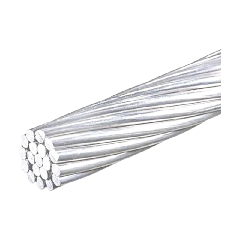
The product range also includes support solutions for steel-cored aluminum strands, commonly known as ACSR conductors. The construction follows the GB1179-83 standard, with nominal cross-sections covering approximately 10/2 mm² to 240/30 mm².
Available technical parameters may include calculated cross-sectional area, outside diameter, direct-current resistance, calculated tensile strength, and calculated weight. These data support conductor selection and help engineers coordinate the conductor with the clamp, support, span, and connection system.
3. Materials Used in Bus-Bar Support Construction
Material selection determines a support’s insulation performance, mechanical strength, thermal stability, resistance to flame, and ability to survive harsh environments. There is no single material that is ideal for every application. The correct choice depends on voltage level, current, temperature, fault force, installation location, contamination, moisture, and required service life.
3.1 Hot-Dip Galvanized Steel
Hot-dip galvanized steel is used for the structural components of the Type MGG fixed hardware and related fittings. The steel provides the mechanical strength needed to carry conductor weight and resist short-circuit forces. The zinc coating provides a sacrificial protective layer that helps prevent corrosion when the hardware is exposed to humidity, rain, salt, industrial pollutants, and outdoor temperature changes.
The stated zinc coating thickness is not less than 85 micrometers for applicable components. A properly controlled hot-dip galvanizing process improves coating continuity and protects edges, recesses, and complex structural surfaces. The final result is more durable than untreated carbon steel and more economical than using a solid corrosion-resistant alloy for every structural part.
3.2 DMC Insulating Materials
Dough molding compound, commonly referred to as DMC, is a thermosetting composite material used in electrical insulating components. It combines resin, glass fiber, mineral fillers, and other additives. DMC can offer high dielectric strength, dimensional stability, flame resistance, and good mechanical performance.
DMC supports are suitable for many low-voltage and medium-voltage assemblies. They are particularly useful where a molded insulating body must withstand mechanical loading while maintaining stable dimensions over a wide temperature range. The material can be formed into complex shapes that include mounting holes, ribs, rounded edges, and controlled clamping surfaces.
3.3 SMC Insulating Materials
Sheet molding compound, or SMC, is another glass-fiber-reinforced thermosetting composite used for electrical supports and structural insulating parts. SMC generally provides very high mechanical strength and good resistance to heat, flame, moisture, and chemical exposure.
Compared with ordinary insulating plastics, SMC and DMC can provide a better balance of electrical insulation and structural rigidity. Typical application data may include temperature resistance ranges such as approximately minus 40 degrees Celsius to 180 degrees Celsius for DMC and minus 50 degrees Celsius to 200 degrees Celsius for SMC. Actual limits depend on formulation, design, test method, and operating conditions.
3.4 Material Comparison
| Material | Primary Strength | Insulation Performance | Temperature Capability | Typical Application |
|---|---|---|---|---|
| DMC | High mechanical strength and dimensional stability | Excellent | Approximately -40°C to 180°C | Low- and medium-voltage busbar supports |
| SMC | Very high strength and impact resistance | Excellent | Approximately -50°C to 200°C | Heavy-duty and reinforced support systems |
| Hot-dip galvanized steel | High structural and load-bearing strength | Requires insulating interface or separate insulator | Suitable for broad outdoor service conditions | Fixed hardware, clamps, frames, and fittings |
The use of a composite insulating body together with galvanized steel structural hardware allows the support system to combine electrical insulation, mechanical strength, corrosion resistance, and practical installation. This hybrid approach is often more effective than relying on a single material for every function.
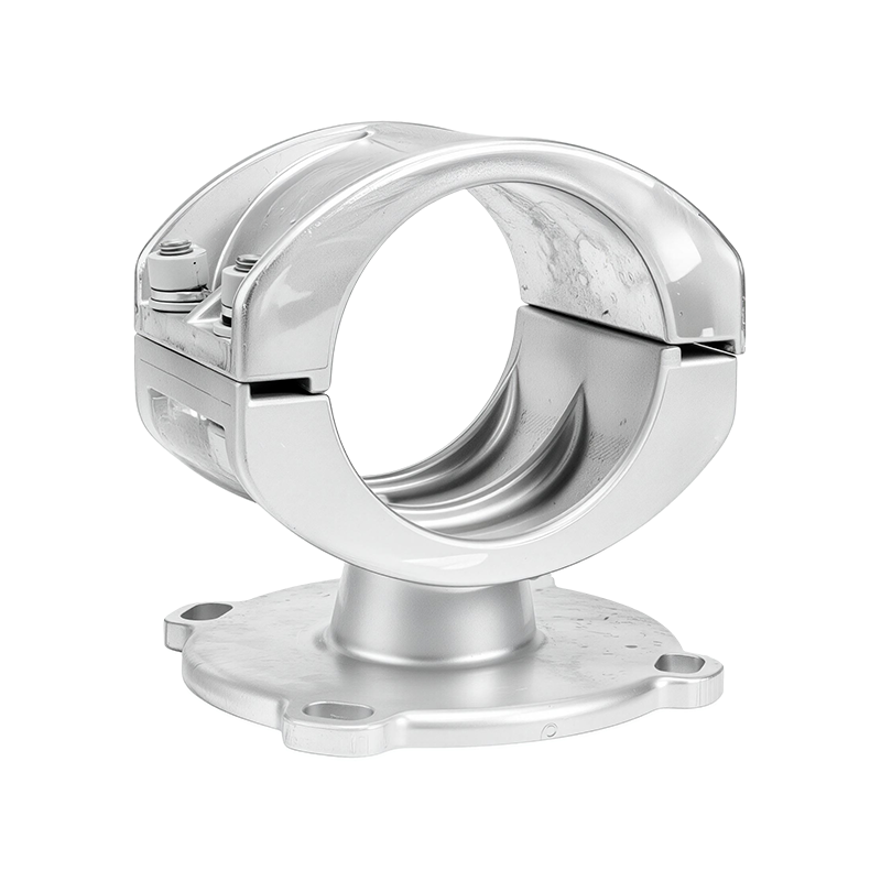
Bus-bar Supports (Fixed Support Type)
4. Technical Advantages of the Fixed Support Type
4.1 Wide Diameter Compatibility
One advantage of the fixed hardware range is its compatibility with tubular busbar outside diameters from approximately 50 mm to 180 mm. This allows a single product family to serve multiple conductor sizes and project configurations. It simplifies engineering selection and makes it easier for contractors and system integrators to standardize support arrangements across different installations.
Wide dimensional coverage is valuable for OEM projects because busbar systems may be adapted to different current ratings, enclosure sizes, span lengths, or connection layouts. A manufacturer capable of producing multiple support sizes can coordinate the hardware with the complete busbar assembly rather than offering an isolated standard component.
4.2 Standard and Reinforced Configurations
Standard and reinforced configurations provide a practical method of matching the support to the mechanical demands of the installation. Standard supports can be used for ordinary service conditions where conductor weight and fault forces remain within the basic design range. Reinforced supports are suitable for heavy tubular conductors, long spans, higher fault currents, vibration-prone sites, or applications requiring additional structural reserves.
This product differentiation provides an advantage over suppliers that offer only one general-purpose support. Instead of overdesigning every installation, the system designer can select an appropriate support class. This can reduce unnecessary material consumption while retaining sufficient safety margins for demanding locations.
4.3 Corrosion Protection for Long-Term Service
Outdoor and industrial electrical equipment may be exposed to humidity, salt spray, ultraviolet radiation, chemical pollutants, and repeated temperature cycling. Corrosion can reduce cross-sectional thickness, weaken fasteners, increase contact resistance, and eventually compromise mechanical stability.
The use of hot-dip galvanized steel, with a zinc coating thickness of at least 85 micrometers for applicable components, improves resistance to atmospheric corrosion. Additional surface treatments, including sandblasting and passivation, can further improve coating adhesion and surface durability. Enhanced anti-corrosion coating solutions can also be considered for coastal regions, chemical plants, offshore facilities, and other locations with severe exposure.
4.4 Low-Temperature Toughness
Electrical infrastructure may operate in regions where temperatures fall to minus 40 degrees Celsius. Materials that become brittle at low temperature may crack under vibration, impact, installation stress, or sudden short-circuit loading. The support material and manufacturing process must therefore preserve toughness over the complete operating temperature range.
Through controlled die-forging and heat-treatment processes, the metal components are designed to maintain suitable mechanical properties and toughness under low-temperature conditions. This is an important advantage for outdoor substations, wind power facilities, northern industrial sites, and transportation infrastructure where seasonal temperature variation is significant.
4.5 Reduced Eddy Current and Electrical Losses
Busbar hardware is located close to high-current conductors. If conductive metal components form unfavorable magnetic loops, eddy-current losses and local heating may occur. These effects can increase the temperature of the support, reduce efficiency, and create thermal stress in nearby insulating materials.
The support design considers electrothermal coupling and electromagnetic behavior. Structural geometry can be optimized to reduce unnecessary current loops and minimize eddy-current losses. For high-current systems, the relationship between the support, conductor, enclosure, fasteners, and adjacent phases should be evaluated as a complete electromagnetic system.
4.6 Controlled Contact Resistance
Metallic connection points should maintain stable electrical contact where current transfer or bonding is required. Poor surface preparation, insufficient clamping force, corrosion, or thermal cycling can increase contact resistance. Higher resistance produces localized heating, which can accelerate oxidation and damage.
The stated design objective is to control contact resistance below 50 microohms in applicable hardware configurations. Actual results depend on contact materials, surface condition, assembly torque, conductor preparation, and operating temperature. A controlled manufacturing process and clear installation instructions are therefore essential for maintaining the intended value in service.
4.7 Anti-Corona Design
In medium- and high-voltage environments, sharp edges, small-radius projections, and uneven interfaces can intensify the local electric field. This may create corona discharge, radio interference, ozone generation, and partial discharge activity. Over time, these effects can degrade insulation surfaces and reduce system reliability.
Rounded profiles, controlled clearances, smooth surfaces, and suitable end-cap geometry help manage the electric field around the busbar assembly. The anti-corona design approach is particularly important for tubular busbars used in substations and other high-voltage equipment where insulation coordination is a primary design requirement.
5. Manufacturing Processes and Quality Control
The performance of a bus-bar support is determined not only by its drawing or material specification but also by the consistency of its manufacturing process. Dimensional deviations, incomplete galvanizing, hidden casting defects, poor heat treatment, or inconsistent assembly can reduce the reliability of an otherwise well-designed product.
5.1 Engineering and Product Development
Manufacturing begins with application analysis. Engineers review the busbar outside diameter, conductor material, current rating, mounting orientation, short-circuit level, span, environmental exposure, and required insulation distance. They then define the support geometry, material, fixing method, allowable stress, and inspection criteria.
Computer-aided design helps control dimensions and coordinate the support with the tubular busbar, mounting frame, end cap, connector, and enclosure. Finite element analysis can be used to study stress distribution, identify high-load regions, and improve the structural design before tooling or production begins.
Finite element analysis is particularly useful for reinforced supports. It can show how a support responds to vertical conductor weight, lateral electromagnetic force, bolt preload, thermal expansion, and impact loading. By improving the stress distribution, the design can avoid unnecessary concentration at corners, bolt holes, or clamping interfaces.
5.2 Die-Forging and Heat Treatment
For structural metal components, die-forging can improve the consistency and strength of the finished part. The process forms the metal under controlled pressure and can produce a more continuous grain structure than some alternative manufacturing methods. This is useful for clamps and fittings that must carry high tension or resist sudden loads.
Heat treatment is used to achieve the required combination of strength, hardness, toughness, and dimensional stability. The treatment cycle must be controlled according to the selected steel grade and component geometry. Excessive hardness without sufficient toughness can increase the risk of brittle failure, while insufficient treatment may reduce load-bearing capability.
5.3 Hot-Dip Galvanizing
After preparation, steel components are immersed in molten zinc during the hot-dip galvanizing process. The zinc coating forms a metallurgical bond with the steel substrate. Surface preparation, bath temperature, immersion time, withdrawal speed, and drainage all affect the coating quality.
Inspection may include coating-thickness measurement, visual examination, adhesion assessment, and verification of coverage in recesses and complex areas. A consistent coating is important because corrosion often begins at unprotected edges, corners, damaged areas, or regions where contaminants remain trapped.
5.4 Composite Molding
DMC and SMC insulating components are manufactured through controlled molding processes. The compound is placed into a heated mold and formed under pressure. The molding conditions influence dimensional accuracy, surface quality, fiber distribution, resin curing, and mechanical performance.
Proper mold design is necessary to avoid voids, incomplete filling, warpage, sharp edges, and uneven wall thickness. The finished support should have clean mounting holes, stable contact surfaces, and sufficient radii to reduce stress concentration. Flame-retardant formulations can be selected for applications where fire safety is a major consideration.
5.5 CNC Machining and Dimensional Control
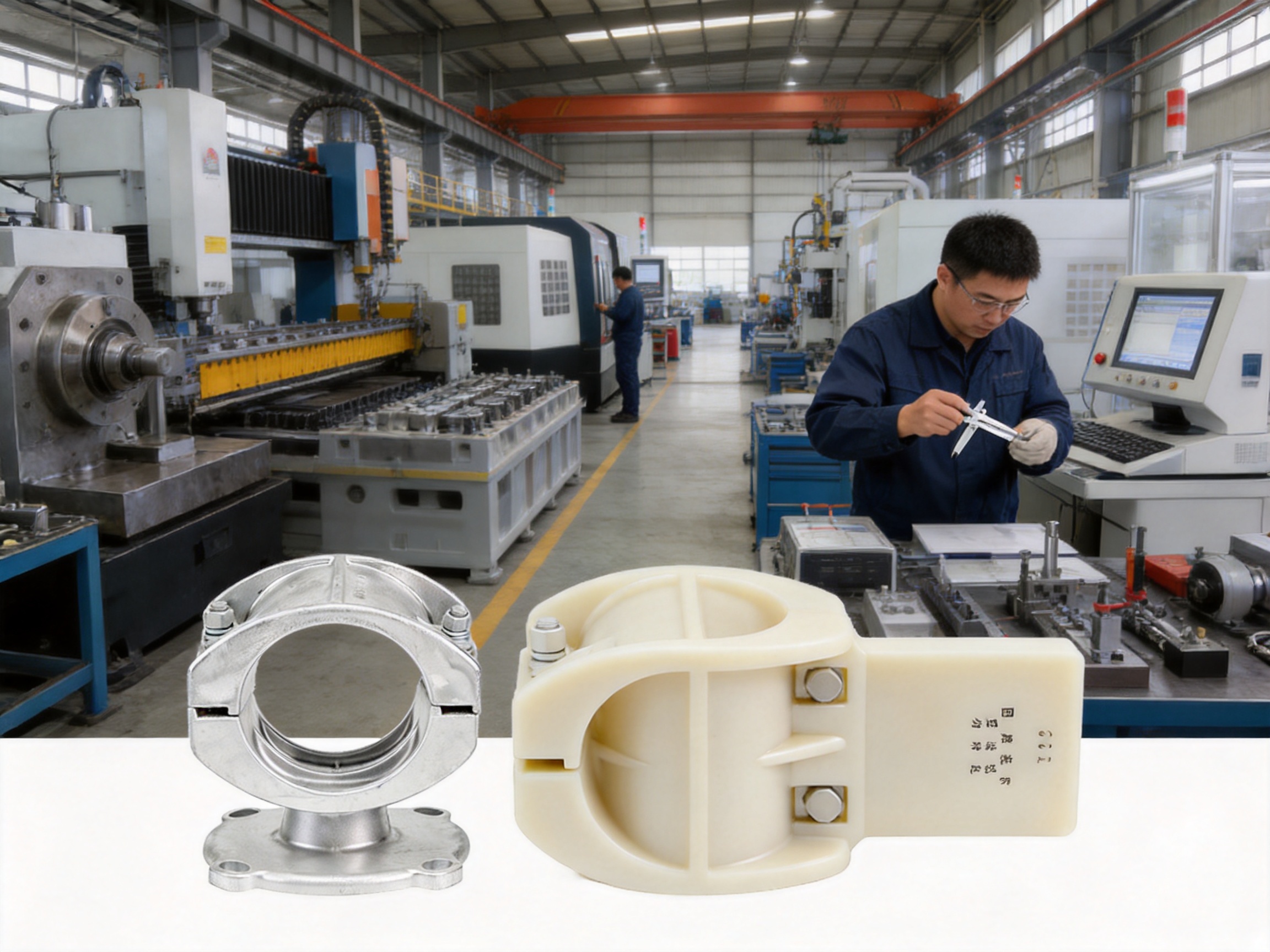
CNC machining is used where accurate holes, interfaces, threads, slots, or finishing surfaces are required. Dimensional accuracy is important because the support must align with the busbar and the supporting frame. Even a small error can create uneven clamping pressure or make installation difficult.
Production inspection may include coordinate measurement, gauge inspection, thread verification, hole-position checks, and surface-finish evaluation. Critical dimensions should be recorded according to the quality plan so that each production batch can be traced and verified.
5.6 Automated Assembly
Automated or semi-automated assembly improves consistency in the installation of bolts, inserts, insulating elements, damping wires, and other parts. It also reduces variation caused by manual handling. Assembly controls may include torque monitoring, component presence detection, orientation verification, and final visual inspection.
Automation does not replace engineering judgment. The assembly process must still be supported by work instructions that define fastener type, tightening sequence, torque value, surface preparation, and inspection criteria. For OEM products, assembly records and traceability are particularly useful for project acceptance and future maintenance.
5.7 Testing and Verification
A complete quality program can include high-voltage testing, insulation testing, mechanical verification, dimensional inspection, contact-resistance measurement, salt-spray testing, ultraviolet aging, temperature cycling, and routine production checks.
The stated environmental performance includes up to 3,000 hours of salt-spray testing and 2,000 hours of ultraviolet aging tests for applicable products or material systems. Stable operation is also targeted through temperature cycling from approximately minus 40 degrees Celsius to 60 degrees Celsius. In humid and hot conditions, the insulation resistance target may remain above 104 megohms for applicable insulating configurations.
Mechanical testing may evaluate static load, grip strength, impact resistance, vibration, fatigue, and short-circuit simulation. The stated fatigue-life objective of 107 vibration cycles reflects the importance of long-term resistance to repeated mechanical stress. Test conditions and acceptance criteria should be confirmed against the particular product standard and project specification.
6. Advantages Over General-Purpose Competitor Products
Many low-cost supports are produced as generic components with limited dimensional options and minimal application guidance. While such products may be acceptable for light-duty installations, they can create problems in high-current or medium-voltage systems. The main advantages of a professionally engineered fixed support are application compatibility, verified mechanical performance, environmental durability, and integration with the complete busbar system.
6.1 Better System Matching
A support designed specifically for tubular busbars can provide a more accurate interface than a universal bracket adapted from another application. Correct geometry distributes clamping pressure and reduces the risk of tube deformation, slippage, or misalignment. A broader range of available diameters also makes it easier to match the support to the actual conductor rather than forcing the conductor into an unsuitable clamp.
6.2 Greater Mechanical Reserve
Reinforced models, forged components, optimized stress distribution, and tested fastening arrangements provide greater mechanical reserve than lightweight general-purpose products. This is particularly important where the installation is exposed to high fault current, wind, earthquake, vibration, or long unsupported spans.
6.3 More Reliable Environmental Performance
Untreated or lightly coated steel may corrode rapidly in coastal and industrial environments. Professionally galvanized components, controlled surface treatment, and optional enhanced coatings offer better resistance to long-term exposure. Composite insulating materials also provide better resistance to moisture, flame, and chemical contamination than many ordinary plastics.
6.4 Improved Electrical Behavior
A support system should not introduce unnecessary hot spots, eddy-current losses, or electric-field concentrations. The use of anti-corona profiles, stable insulating materials, controlled contact resistance, and coordinated electromagnetic design gives professionally engineered products an advantage in high-current and medium-voltage installations.
6.5 Customization and OEM Support
Electrical equipment manufacturers often require custom hole patterns, nonstandard diameters, special coatings, reinforced structures, modified terminals, or coordinated busbar accessories. A manufacturer with engineering and production capabilities can adapt the support to the project rather than limiting the customer to a fixed catalog item.
OEM cooperation also requires stable documentation, repeatable quality, packaging control, production scheduling, and technical communication. These capabilities reduce integration risk and help customers maintain consistent product performance across multiple projects.
7. Applications in Power Distribution and Infrastructure
7.1 Low-Voltage Switchgear
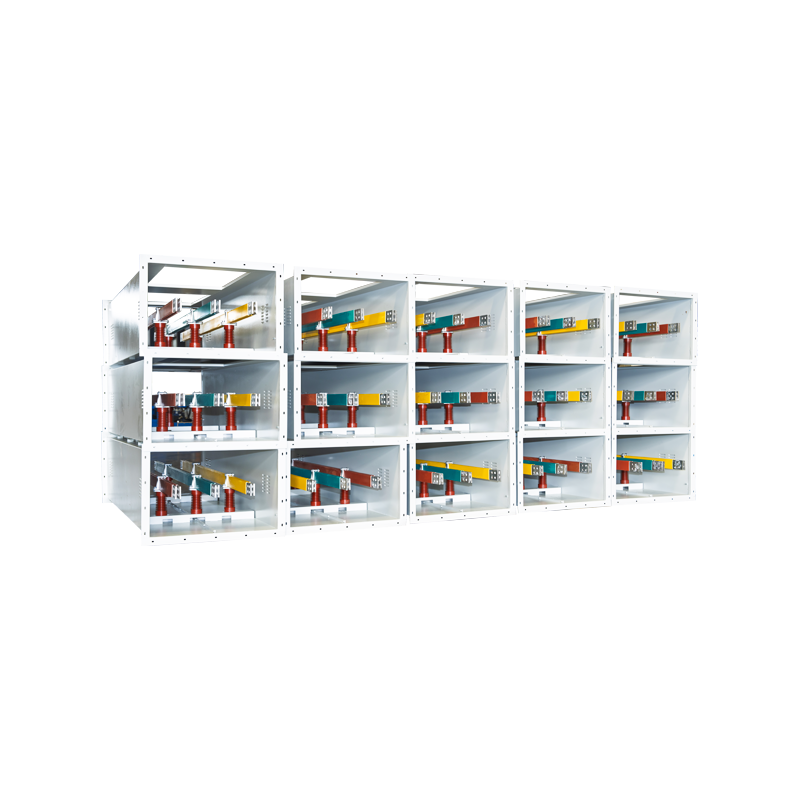
In low-voltage switchgear and distribution cabinets, fixed supports keep copper or aluminum busbars aligned and separated. The supports must withstand thermal effects from continuous current and fault forces from short-circuit events. Flame retardancy, compact dimensions, and ease of assembly are important in enclosed cabinets.
7.2 Medium-Voltage Distribution Equipment
Medium-voltage equipment requires careful insulation coordination and control of creepage and clearance distances. Fixed supports used in these systems must combine mechanical stability with suitable dielectric performance. Anti-corona design, surface quality, and resistance to humidity become increasingly important as voltage increases.
7.3 Substations and Transformer Connections
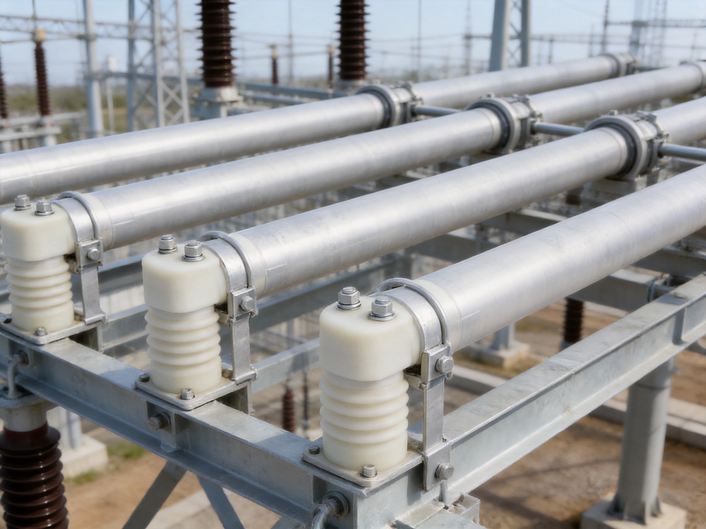
Substations often use tubular busbars for connections between transformers, switchgear, disconnectors, and other equipment. These installations may be outdoors and exposed to ultraviolet radiation, rain, salt, wind, and temperature changes. Corrosion-resistant fixed hardware and sealed end caps help preserve the reliability of the conductor assembly.
7.4 Wind Power Installations
Wind turbines produce continuous vibration and cyclic mechanical loading. Busbar supports and damping accessories must accommodate these conditions without allowing conductor movement or progressive fatigue damage. Damping end caps equipped with suitable damping wires can help improve the behavior of tubular busbar connections in vibration-prone environments.
7.5 Renewable Energy Grid Connection Cabinets
Solar and wind energy systems often include high-current connections between converters, transformers, switchgear, and grid-interface equipment. Compact and reliable busbar supports help maintain phase separation and reduce the risk of failure inside cabinets with limited installation space.
7.6 Industrial Manufacturing Facilities
Factories may contain welding equipment, motors, variable-frequency drives, furnaces, compressors, and other loads that create high current demand and electrical disturbances. The busbar support system must maintain alignment during repeated switching events and withstand the vibration associated with industrial machinery.
7.7 Rail Transit and Large Commercial Buildings
Rail transit systems and large commercial facilities require reliable power distribution across long routes and high-occupancy environments. Supports must be durable, flame resistant, easy to inspect, and compatible with compact equipment layouts. The reliability of small components is important because a failure in a critical distribution section can interrupt transportation, building services, or emergency systems.
8. Selecting the Correct Fixed Bus-Bar Support
Selection should begin with the tubular busbar outside diameter. For Type MGG fixed hardware, the applicable range is approximately 50 mm to 180 mm. The engineer should verify the actual measured diameter, dimensional tolerance, surface coating, and any protective sleeve or interface that changes the effective clamping size.
The next consideration is the electrical system. Voltage level determines insulation requirements, clearance, creepage distance, electric-field control, and possible corona concerns. Current rating influences conductor size, thermal expansion, and the temperature of nearby support materials. Short-circuit current determines the mechanical load that the support must withstand.
Environmental conditions should also be reviewed. Outdoor installations may require improved ultraviolet and corrosion resistance. Coastal sites may need enhanced coating protection. Cold regions require low-temperature toughness. Humid or polluted environments require careful consideration of insulation surface performance, tracking resistance, and cleaning access.
Installation orientation affects the load path. A vertical support may carry primarily the weight of the conductor, while a horizontal support may experience greater lateral and bending forces. Suspended, wall-mounted, cabinet-mounted, and frame-mounted arrangements should be evaluated separately.
Finally, the complete hardware set should be checked. The support, end cap, clamp, bolt, washer, connector, damping element, and mounting frame must be compatible. A strong support cannot compensate for an unsuitable fastener or weak supporting structure.
| Parameter | Why It Matters | Typical Engineering Check |
|---|---|---|
| Busbar outside diameter | Ensures correct fit and clamping pressure | Compare measured diameter with the support range |
| Voltage level | Determines insulation and clearance requirements | Verify creepage, clearance, and dielectric performance |
| Continuous current | Influences conductor temperature and thermal expansion | Review heat transfer and support temperature rating |
| Short-circuit current | Determines electrodynamic loading | Calculate force and confirm support spacing and strength |
| Installation environment | Affects corrosion, moisture, ultraviolet, and temperature performance | Select suitable coating and insulating material |
| Support spacing | Controls sag, vibration, and fault movement | Coordinate with conductor weight and mechanical calculations |
| Mounting structure | Transfers the support load into the equipment or frame | Verify frame strength, bolt capacity, and alignment |
9. Installation and Maintenance Recommendations
Before installation, the support and busbar should be inspected for damage, contamination, deformation, missing components, or coating defects. The mating surfaces should be clean and free from oil, loose particles, and excessive oxidation. Damaged insulating parts should not be installed.
The tubular busbar should be positioned centrally in the support. The clamp should not create a sharp local pressure point, and the conductor should not be forced into alignment by excessive bolt tightening. If the system includes thermal expansion joints or sliding points, fixed supports must be installed only at the locations defined by the engineering design.
Fasteners should be tightened using the specified sequence and torque. Under-tightening can allow movement and increase contact resistance, while over-tightening may damage the support, deform the busbar, or reduce the service life of the fastener. Torque records are recommended for critical installations.
After installation, the system should be inspected for phase clearance, conductor alignment, support spacing, bolt condition, end-cap installation, and connection quality. Electrical tests should be completed before energization, including insulation resistance and any required high-voltage or continuity tests.
During maintenance, inspection personnel should look for corrosion, cracked insulating parts, discoloration, loosened fasteners, unusual noise, surface tracking, signs of overheating, and conductor movement. Thermal imaging can help identify abnormal heating at connections or areas with increased contact resistance.
Maintenance intervals depend on the environment and system importance. Outdoor substations, coastal facilities, wind turbines, and heavily polluted industrial sites may require more frequent inspection than clean indoor switchgear. If a support has experienced a major short-circuit event, it should be inspected even when no external damage is immediately visible.
10. Manufacturing Strengths and Customization Capability
Jiangsu Wopeng Power Technology Co., Ltd. was founded in 2018 as a specialized high-tech enterprise focused on high- and low-voltage busbar systems. The company combines product development, engineering support, manufacturing, inspection, and technical service within one organization.
Its product portfolio covers 35 kV epoxy resin vacuum-cast tubular busbars, low-voltage cast-resin busways, copper and aluminum tubular busbars, wind power tubular busbars, compact busbar systems, insulated busbars, and sliding contact line power supply systems. This broad product scope enables the company to understand the interaction between busbars and their support hardware.
For customers purchasing fixed supports, this system-level experience is valuable. The support can be evaluated together with the conductor, insulation, enclosure, connection hardware, and installation structure. Problems caused by mismatched dimensions or incompatible materials can be identified earlier in the engineering process.
The company operates production lines equipped with vacuum casting systems, CNC machining equipment, and automated assembly technologies. Vacuum casting helps improve the consistency and insulation quality of epoxy resin components by reducing voids and controlling the material structure. CNC machining provides accurate dimensions for metal and composite components, while automated assembly improves repeatability.
Manufacturing is supported by a quality management system and standardized inspection procedures. Product checks may include high-voltage testing, insulation testing, mechanical verification, dimensional inspection, and routine quality control. Cooperation with third-party testing institutions provides an additional level of independent validation for safety and performance.
Wopeng also provides customized OEM solutions. Customization may include support dimensions, reinforced structures, mounting-hole patterns, special terminal arrangements, coating requirements, damping accessories, packaging, identification marks, and coordinated busbar assemblies. The customer can provide drawings, samples, performance requirements, or application data for engineering review.
A customized approach is especially useful when a project has unusual conductor sizes, limited cabinet space, high seismic requirements, unusual temperature conditions, or a demanding corrosion environment. Instead of adapting a generic support through field modification, the customer can obtain a component designed for the intended installation from the beginning.
11. Why System-Level Quality Matters
A busbar system is only as reliable as its weakest component. A high-quality tubular conductor can still experience operational problems if the support allows excessive movement. A strong metal clamp can still fail if its insulating interface cracks. A corrosion-resistant component may still overheat if contact resistance is not properly controlled.
System-level quality requires coordination between mechanical, electrical, thermal, and environmental design. The support must fit the conductor, the conductor must fit the end cap, the end cap must provide the required sealing or damping function, and the complete assembly must connect correctly to the supporting frame.
This principle is one of the main differences between a professional busbar support manufacturer and a general hardware supplier. A specialized manufacturer can evaluate the complete operating condition, provide technical documentation, coordinate related accessories, and support testing and installation. This reduces the chance that a component selected only by appearance or nominal size will be used in a demanding application.
12. Frequently Asked Questions
Q1: What is a fixed bus-bar support?
A fixed bus-bar support is a mechanical and insulating component used to hold a busbar at a defined position. It maintains electrical clearance, prevents unwanted movement, and transfers conductor loads into a supporting frame or enclosure. In tubular busbar systems, it is normally selected according to the outside diameter and mechanical requirements of the tube.
Q2: What tubular busbar diameters are supported by Type MGG fixed hardware?
Type MGG fixed hardware is designed for tubular busbar outside diameters from approximately 50 mm to 180 mm. The exact model should be selected according to the actual conductor diameter, installation configuration, required load capacity, and applicable technical drawing.
Q3: When should a reinforced fixed support be used?
A reinforced support should be considered for heavy conductors, high short-circuit current, long support spans, strong vibration, seismic areas, outdoor installations with significant wind loading, or any application requiring additional mechanical reserve. The final selection should be confirmed through mechanical calculations and system testing.
Q4: Are fixed bus-bar supports suitable for both low-voltage and medium-voltage systems?
Yes. Fixed supports can be used in low-voltage and medium-voltage distribution systems when the selected material, insulation structure, clearance, creepage distance, and mechanical rating meet the requirements of the installation. Typical applications may range from 0.4 kV to 35 kV, depending on the product design and system specification.
Q5: What materials are commonly used for insulated bus-bar supports?
DMC and SMC composite materials are commonly used because they provide high electrical insulation, good mechanical strength, flame resistance, dimensional stability, and environmental durability. Hot-dip galvanized steel is commonly used for structural hardware, clamps, brackets, and fittings where high mechanical strength is required.
Q6: How does hot-dip galvanizing improve support performance?
Hot-dip galvanizing applies a bonded zinc coating to the steel surface. The coating protects the steel from atmospheric corrosion and provides sacrificial protection when the surface is exposed to moisture or minor damage. For applicable Wopeng hardware, the stated zinc coating thickness is not less than 85 micrometers.
Q7: What is the purpose of an MGF end cap?
An MGF end cap seals the end of a tubular busbar and helps prevent the entry of moisture, dust, and contaminants. Standard, damping, and terminal-ball types are available. Damping types may include LGJ-series damping wires to improve resistance to vibration and seismic effects.
Q8: How should support spacing be determined?
Support spacing should be determined from the conductor weight, outside diameter, span, mounting orientation, thermal expansion, short-circuit force, vibration, wind loading, and support mechanical rating. The spacing should be verified through an engineering calculation rather than selected solely from a general rule.
Q9: Can bus-bar supports be customized for OEM projects?
Yes. Customization can include dimensions, mounting-hole locations, reinforced structures, special coatings, terminal arrangements, damping accessories, materials, packaging, and coordinated busbar hardware. OEM projects should provide the conductor data, electrical requirements, environmental conditions, drawings, and expected production quantity.
Q10: What inspections should be completed before energizing a busbar system?
Pre-energization inspections should include dimensional and visual checks, conductor alignment, phase clearance, support spacing, fastener torque, end-cap installation, insulation condition, connection quality, insulation resistance, and any required dielectric or high-voltage tests. The inspection scope should follow the project specification and applicable standards.
Q11: How can overheating at a support or connection be prevented?
Overheating can be reduced by using correctly sized hardware, clean contact surfaces, suitable contact pressure, proper fastener torque, compatible materials, and a design that limits eddy-current losses. Thermal imaging during commissioning and maintenance can help identify abnormal heating before it develops into a serious failure.
Q12: Why is a specialized manufacturer preferable to a general hardware supplier?
A specialized manufacturer understands the relationship between the conductor, support, insulation, enclosure, electrical field, thermal behavior, and short-circuit forces. It can provide coordinated accessories, engineering verification, customized designs, production traceability, testing documentation, and technical assistance for installation and maintenance.
13. Conclusion
Fixed bus-bar supports are fundamental components in safe and durable tubular busbar systems. Their responsibilities extend beyond simple mechanical mounting. They maintain electrical spacing, resist short-circuit forces, control vibration, support thermal stability, protect against environmental exposure, and contribute to the overall electrical performance of the assembly.
Type MGG fixed hardware provides a broad diameter range for tubular busbars from approximately 50 mm to 180 mm, with standard and reinforced configurations for different mechanical requirements. Related Type MGF end caps, tension clamps, damping elements, and ACSR support products allow engineers to create a coordinated hardware package for complete power transmission and distribution systems.
The combination of hot-dip galvanized steel, DMC or SMC insulating materials, die-forging, heat treatment, CNC machining, vacuum casting, automated assembly, and standardized testing provides important advantages over generic competitor products. These advantages include better dimensional compatibility, higher mechanical reliability, improved corrosion resistance, controlled electrical performance, and greater customization potential.
With engineering experience in high- and low-voltage busbar systems, Jiangsu Wopeng Power Technology Co., Ltd. supports customers in substations, industrial plants, renewable energy projects, rail transit, wind power, commercial buildings, and other critical infrastructure. By selecting a fixed support according to conductor size, voltage, current, fault force, environment, and installation structure, users can improve the safety, service life, and reliability of the entire tubular busbar system.
References
1. GB 1179-83, Round Wire Concentric Lay Overhead Electrical Stranded Conductors.
2. IEC 61439, Low-Voltage Switchgear and Controlgear Assemblies.
3. IEC 62271, High-Voltage Switchgear and Controlgear.
4. IEC 60071, Insulation Coordination.
5. IEC 60695, Fire Hazard Testing for Electrotechnical Products.
6. UL 94, Tests for Flammability of Plastic Materials for Parts in Devices and Appliances.
7. ISO 1461, Hot-Dip Galvanized Coatings on Fabricated Iron and Steel Articles.
8. General principles of finite element analysis for mechanical stress distribution and fatigue assessment.
9. Technical product information for Type MGG fixed hardware, Type MGF end caps, tension clamps, and tubular busbar support systems.
Product: Bus-bar Supports (Fixed Support Type)




-
 +86-180 3625 3000
-
 admin@wpbusbar.com
-
 No. 8, Yanjin Road, Chengxi Industrial Park, Shanyang Town, Baoying County, Yangzhou City, Jiangsu Province, China
Copyright © Jiangsu Wopeng Power Technology Co., Ltd.
All Rights Reserved.
 Custom Insulated Bus Bar Manufacturer
Tubular Busbar System Factory
Custom Insulated Bus Bar Manufacturer
Tubular Busbar System Factory