

 EN
EN

 English
 русский
 Français
 Español
 عربى
عربى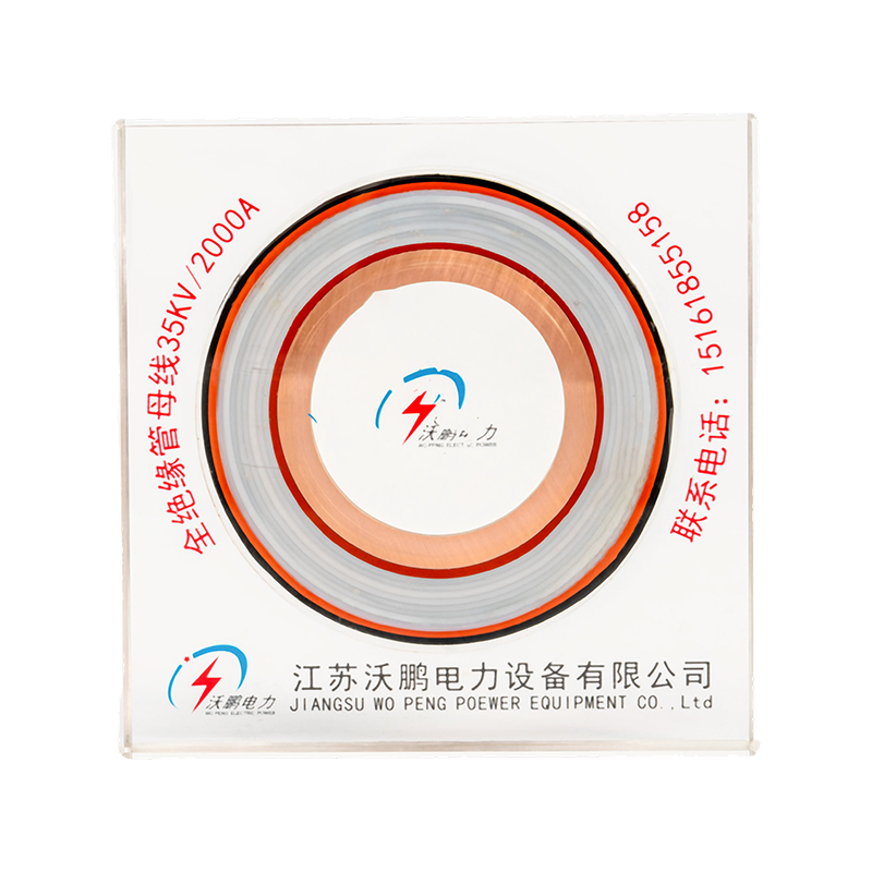


Epoxy Resin Casting Tubular Bus Bar: Design, Performance, Manufacturing, and Applications
Content
- 1 1. What Is an Epoxy Resin Casting Tubular Bus Bar?
- 2 2. How the Vacuum Casting Manufacturing Process Works
- 3 3. Main Technical Advantages
- 4 4. Environmental Operating Conditions
- 5 5. Comparison with Conventional Busbar and Cable Solutions
- 6 6. Applications in Power and Infrastructure Projects
- 7 7. Typical Installation Arrangements
- 8 8. Manufacturing and Engineering Strengths
- 9 9. Design and Selection Guidelines
- 10 10. Installation, Testing, and Maintenance
- 11 11. Why This Product Can Outperform Competing Solutions
- 12 12. Frequently Asked Questions
- 12.1 Q1: What is an Epoxy Resin Casting Tubular Bus Bar used for?
- 12.2 Q2: What conductor material is used?
- 12.3 Q3: What voltage levels are available?
- 12.4 Q4: What is the expected service life?
- 12.5 Q5: Can the busbar be installed outdoors?
- 12.6 Q6: What is the maximum current-carrying capacity?
- 12.7 Q7: Why is vacuum casting important?
- 12.8 Q8: How are the joints connected?
- 12.9 Q9: How is the metal shield grounded?
- 12.10 Q10: What is the maximum suspended span?
- 12.11 Q11: Does the product require extensive maintenance?
- 12.12 Q12: What information should be supplied when requesting a quotation?
- 13 13. Conclusion
- 14 References
- 15 Product: Epoxy Resin Casting Tubular Bus Bar
Modern power systems require conductors that can transmit large currents safely while maintaining electrical insulation, mechanical stability, environmental resistance, and long service life. Conventional open busbars, cable arrangements, and some older insulated busbar designs may become difficult to manage when installations involve high current, limited space, humidity, dust, vibration, or demanding fire-safety requirements. Epoxy Resin Casting Tubular Bus Bar addresses these challenges by combining a tubular conductor with a continuously cast insulation system and an integrated shielding structure.
This type of busbar is designed as a compact, robust, and highly insulated power transmission component for medium- and high-voltage applications. Instead of relying on multiple detachable insulation components, the conductor, insulation system, shielding layers, and protective exterior are integrated through vacuum pressure casting and high-temperature curing. The resulting structure is nonseparable, mechanically strong, and resistant to many of the environmental conditions that can affect exposed conductors and conventional cable installations.
Jiangsu Wopeng Power Technology Co., Ltd. develops and manufactures high- and low-voltage busbar systems, including epoxy resin vacuum-cast tubular busbars, low-voltage cast-resin busways, copper and aluminum tubular busbars, wind power tubular busbars, compact busbar systems, and sliding contact line systems. Its engineering and manufacturing capabilities support customized power transmission solutions for substations, power generation facilities, industrial plants, renewable energy installations, rail transit projects, and large commercial buildings.
The product described in this article is manufactured through a fully automated two-component vacuum injection molding process. Pressure injection and high-temperature curing are used to create a continuous insulation structure around the conductor. Insulation joints and copper conductors are formed in a single molding operation, while intermediate connections use embedded stainless steel clamp welding. This design improves connection reliability and helps keep the temperature rise at terminal joints below the temperature rise of the conductor body.
With suitable configuration, the busbar can be used in systems covering several voltage levels. The stated insulation thickness references include 10 mm for 10 kV, 15 mm for 35 kV, 20 mm for 66 kV, 30 mm for 110 kV, and 45 mm for 220 kV. Final design selection should be confirmed according to the rated voltage, insulation coordination, current rating, installation environment, short-circuit requirements, and applicable project standards.
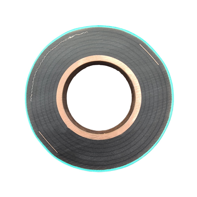
Epoxy Resin Casting Tubular Bus Bar
1. What Is an Epoxy Resin Casting Tubular Bus Bar?
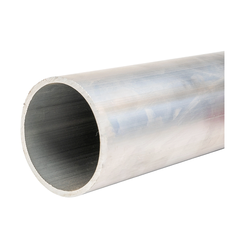
An Epoxy Resin Casting Tubular Bus Bar is a power transmission product in which a metal tubular conductor is surrounded by a molded epoxy resin insulation system. The conductor may be manufactured from high-conductivity copper or, depending on the product series and project requirements, aluminum alloy. For the product described here, the conductor uses TZ7 or higher-grade oxygen-free copper, with a stated copper content of at least 99.90 percent for the pure copper tube.
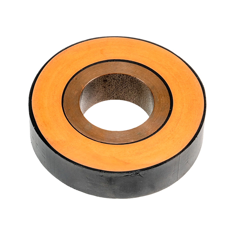
The central conductor carries electrical current. Around it, the product incorporates several functional layers, including an inner shielding layer, semiconductive crepe paper, an outer shielding layer, a metal shielding layer, and an outer protective layer. These layers are formed into an integrated structure during the vacuum casting process. Because the layers are molded together rather than assembled as loosely connected components, the finished busbar has a nonseparable construction.
The epoxy resin insulation provides electrical separation between the energized conductor and the surrounding environment. It also gives the busbar mechanical rigidity, resistance to vibration, and protection against moisture, dust, and many forms of contamination. The external shielding and grounding system support safe fault-current management and help control the electrical field around the conductor.
Unlike a conventional open busbar, the cast tubular design does not leave the energized conductor exposed to the atmosphere. Unlike a cable system, it uses a rigid tubular conductor and can be engineered as a compact, precisely routed connection between transformers, switchgear, control cabinets, and other major electrical equipment. This makes it suitable for installations where high current, restricted routing space, and dependable insulation must be addressed at the same time.
1.1 Integrated Electrical and Mechanical Structure
The product structure is formed in one controlled casting cycle. The conductor, insulation system, shielding layers, and protective outer layer become one integrated body. This reduces the number of interfaces that could otherwise become weak points during transportation, installation, thermal cycling, or long-term operation.
The integrated structure also improves dimensional consistency. When insulation is applied through an automated mold and controlled resin injection process, the manufacturer can better manage resin distribution, curing conditions, and the relationship between the conductor and the insulation wall. This is especially important for medium- and high-voltage equipment, where voids, uneven insulation, or uncontrolled interfaces can affect dielectric performance.
1.2 Conductive Material
Electrical conductivity, thermal performance, and connection quality depend strongly on conductor material. The product specification calls for TZ7 or higher-grade copper, with a copper content of at least 99.90 percent for the pure copper tube. High-purity copper offers low electrical resistance and good heat dissipation, which are important for high-current transmission.
The conductor ends are prepared to support low-resistance connections. The end of the copper tube should be rounded, and the connection surface may be silver-plated or tin-plated. These treatments help reduce contact resistance and improve corrosion resistance at the joint. The final plating method should be selected based on the current rating, connection design, environmental conditions, and project specification.
1.3 Insulation and Shielding System
The insulation system is based on epoxy resin casting. The resin is injected under vacuum and cured at elevated temperature to create a dense, durable insulation layer. The structure also includes semiconductive and shielding elements that help control electrical stress and provide a defined grounding path.
The metal shielding layer is manufactured from a composite of tinned steel strip and copper strip according to the stated product structure. In other sections of the technical requirements, copper braided tape and copper strip are also referenced as shielding materials. The exact material combination should therefore be confirmed in the approved technical drawings and project documentation for each order.
The grounding lead is reliably welded to the metal shielding layer. Grounding points must be securely connected to the site grounding system, protected against water and moisture intrusion, and clearly marked and numbered. A properly designed grounding system allows the shield to perform its protective function and supports safe maintenance and fault management.
2. How the Vacuum Casting Manufacturing Process Works
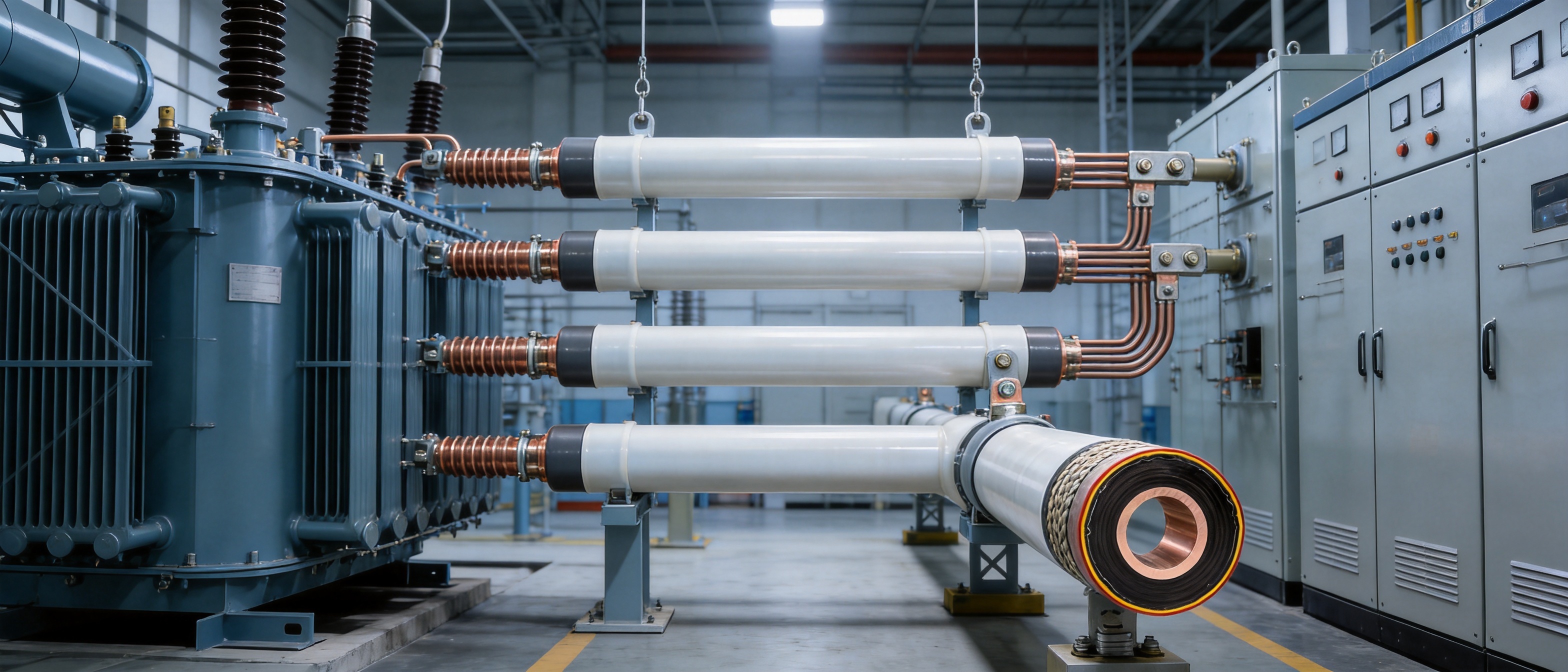
The manufacturing process is one of the most important advantages of an epoxy resin casting tubular busbar. The product is not simply wrapped or assembled from separate insulation parts. It is formed by a controlled, automated process that combines material preparation, vacuum treatment, pressure injection, molding, and high-temperature curing.
2.1 Two-Component Resin Preparation
Epoxy casting systems generally use two liquid components that must be accurately proportioned and thoroughly mixed before injection. A fully automatic dual-mode or two-component vacuum injection molding machine controls the delivery and mixing process. Automated proportioning helps maintain consistent resin chemistry from one production cycle to the next.
Correct resin preparation is essential because incomplete mixing, incorrect ratios, excessive moisture, or uncontrolled material temperature can affect curing and insulation performance. The production process is therefore supported by controlled material handling and standardized operating procedures.
2.2 Vacuum Treatment
Vacuum processing removes air and reduces the possibility of voids within the resin system. In medium- and high-voltage insulation, void control is particularly important because air pockets can create localized electrical stress and contribute to partial discharge or insulation deterioration.
By applying vacuum conditions before and during injection, the manufacturing system helps improve resin penetration and promotes a more homogeneous insulation structure. The vacuum process also supports better bonding between the conductor, semiconductive layers, shielding components, and outer protective layer.
2.3 Pressure Injection and Mold Filling
After the materials and mold have been prepared, the mixed resin is injected under controlled pressure. Pressure injection helps the resin flow around the conductor and fill the designed insulation space. The mold establishes the external dimensions and helps maintain the intended relationship between the conductor and the insulation layers.
A controlled molding process is valuable for long tubular sections because the product must maintain consistent geometry over its length. The maximum suspension span for the described suspended tubular busbar is not more than 5 meters. This requirement helps limit mechanical stress and deflection during installation and operation.
2.4 High-Temperature Curing
High-temperature curing transforms the injected resin into a rigid thermoset insulation system. The curing cycle must be controlled for temperature, time, and uniformity. Insufficient curing can reduce mechanical and dielectric performance, while excessive or uneven curing may create unwanted internal stress.
Once cured, the resin cannot be remelted and reshaped in the same manner as a thermoplastic material. This contributes to the product’s nonseparable construction and long-term dimensional stability. The finished busbar is designed to provide flame-retardant performance and aging resistance, with a stated service life of more than 30 years under appropriate operating conditions.
2.5 Inspection and Quality Control
Jiangsu Wopeng Power Technology operates production lines equipped with vacuum casting systems, CNC machining equipment, and automated assembly technologies. Its quality procedures include high-voltage tests, insulation tests, mechanical verification, and routine inspections. Cooperation with third-party testing institutions provides additional independent validation for selected products and projects.
Quality control should begin with incoming inspection of conductors, copper strips, steel strips, resin components, fasteners, and auxiliary materials. During production, key parameters such as resin ratio, vacuum level, injection pressure, curing temperature, mold condition, conductor dimensions, and shielding continuity should be controlled. Final inspection should verify electrical insulation, conductor resistance, dimensional accuracy, joint quality, grounding continuity, and appearance.
3. Main Technical Advantages
3.1 Seamless Integrated Insulation
The most distinctive feature of the product is its integrated insulation structure. The insulation joint and copper conductor are molded together in one operation, creating a seamless, interface-free fusion. This is different from a construction that depends on multiple detachable insulation components or numerous mechanically assembled layers.
Fewer interfaces can reduce the risk of looseness, moisture penetration, contamination accumulation, and localized stress concentration. It also simplifies inspection because the insulation system is formed as one body rather than assembled from many separate pieces.
3.2 Strong Flame Retardance and Aging Resistance
Fire safety is a major consideration in substations, data centers, hospitals, high-rise buildings, transportation facilities, and industrial plants. The cast epoxy resin structure is designed to provide flame-retardant performance. The product information also identifies aging resistance and a service life of more than 30 years.
Long service life depends on correct design, installation, operating temperature, electrical loading, environmental exposure, and maintenance. Nevertheless, the rigid thermoset insulation system provides a strong foundation for long-term reliability because it resists deformation and maintains its shape under normal thermal conditions.
3.3 Reduced Exposure to Moisture and Contamination
Moisture, dust, salt, and industrial contaminants can reduce the reliability of exposed electrical equipment. The fully insulated tubular structure limits direct exposure of the conductor and primary insulation to the surrounding atmosphere. Waterproof and moistureproof measures are applied around grounding points, terminal structures, and other vulnerable locations.
The insulated outer cover of the grounding screen should prevent moisture intrusion. Heat-shrink insulation bushings may be used where appropriate, and phase colors such as yellow, green, and red should be applied in visible locations for identification. These measures improve safety during installation, inspection, and maintenance.
3.4 Reliable Joint Temperature Performance
Connections are often among the most temperature-sensitive parts of a high-current conductor system. Poor contact pressure, surface oxidation, inadequate plating, or improper alignment may increase contact resistance and create excessive heat.
The product uses embedded stainless steel clamp welding for intermediate connections. The stated design objective is for the temperature rise at terminal joints to remain lower than the temperature rise of the conductor body. Terminal connections to equipment are completed through flexible links secured with bolts. This arrangement allows the rigid tubular busbar to connect to equipment while accommodating installation tolerances and limited movement.
3.5 Mechanical Rigidity and Compact Routing
The epoxy resin body provides mechanical strength in addition to insulation. A tubular conductor also offers favorable structural characteristics and can be routed in a controlled path between major electrical components. Compared with a large group of parallel cables, a tubular busbar may provide a cleaner and more compact arrangement, particularly where high current requires many cable runs.
Its rigid construction can reduce cable support complexity and help maintain phase spacing. However, support spacing, expansion allowances, suspension length, seismic loading, and connection flexibility must be designed according to the project conditions. The stated maximum suspended span is 5 meters, and the support arrangement must be confirmed by the manufacturer’s engineering team.
3.6 Shielding and Grounding Safety
A fully shielded structure provides a controlled electrical environment around the conductor. The metal shield is connected to the grounding system using copper stranded or braided conductors that are reliably welded to the shield layer. Grounding points are marked and numbered to support accurate installation and testing.
During field construction, metal welding areas should receive anti-rust treatment. All bolts and screws used in the installation should be hot-dip galvanized unless a project specification requires another approved material. These details help preserve mechanical integrity and grounding reliability over the service life of the system.
4. Environmental Operating Conditions
The product is designed for demanding operating environments. The stated altitude limit is up to 4,000 meters. At higher altitudes, reduced air density can affect external insulation, heat dissipation, and insulation coordination, so altitude corrections and project-specific verification may be necessary.
The environmental temperature range provided for the product includes a minimum ambient air temperature of -45 degrees Celsius and a maximum ambient air temperature of +60 degrees Celsius. The maximum daily temperature variation is 35 K. These conditions indicate that the busbar can be engineered for severe cold, high heat, and rapid daily temperature changes, provided that the complete system, including joints, supports, and equipment interfaces, is evaluated accordingly.
The stated solar radiation intensity is 1,000 W/m². The maximum wind speed is 40 m/s, based on the specified averaging condition. The product requirements also reference daily average relative humidity of no more than 95 percent and monthly average relative humidity of no more than 90 percent. Ice thickness should not exceed 20 mm unless special engineering measures are adopted.
For seismic design, the stated conditions include seismic intensity of 8 degrees, ground horizontal acceleration of 0.20 g, vertical acceleration of 0.15 g, a frequency of 20 Hz, and a sine-wave endurance duration of three cycles. A safety factor greater than 1.67 is specified. These values provide a basis for structural evaluation, although final seismic calculations must account for the complete busbar route, support system, equipment connections, and building structure.
4.1 Pollution and Creepage Considerations
The technical information references severe pollution design conditions and a creepage distance of 31 mm per kilovolt according to the applicable standard framework. Outdoor terminals may use climbing devices or extended creepage arrangements, with the total climbing distance stated as not less than 680 mm for the relevant configuration.
Pollution performance depends on the local atmosphere, including salt spray, industrial dust, chemical deposits, and humidity. The insulation system, terminal design, external profile, and cleaning requirements must be evaluated together. A cast resin body can reduce contamination exposure, but external terminals and interfaces still require appropriate creepage distance and environmental protection.
4.2 Temporary Overvoltage
The project information specifies that temporary overvoltage should not exceed eight hours within a 24-hour period and should not exceed 125 hours during a full year. These limits should be considered during insulation coordination and system protection design. Surge arresters, grounding arrangements, switching procedures, and relay protection should be selected to protect the busbar and connected equipment.
5. Comparison with Conventional Busbar and Cable Solutions
Product selection should be based on the complete electrical and mechanical system rather than on one isolated parameter. Epoxy Resin Casting Tubular Bus Bar offers several advantages compared with open busbars, conventional cable groups, and some flexible insulated busbar products.
| Evaluation Item | Epoxy Resin Casting Tubular Bus Bar | Open Busbar | Multiple Cable Runs | Flexible Insulated Busbar |
|---|---|---|---|---|
| Primary insulation | Integrated cast epoxy resin system | Usually relies on air clearance and external insulators | Individual cable insulation | Flexible polymer or composite insulation |
| Protection from dust and moisture | Very strong for the insulated body; terminals require protection | Limited without an enclosure | Depends on cable jacket, glands, and installation route | Generally good, depending on material and sealing |
| Mechanical rigidity | High | High when properly supported, but exposed | Low to moderate; requires cable supports | Lower than rigid tubular systems |
| Routing appearance | Compact and orderly | Clear but requires larger clearances | Can become crowded at high current | Compact but may require careful support |
| Joint construction | Embedded connection and flexible equipment links | Bolted or clamped exposed connections | Cable lugs, glands, and multiple terminations | Factory or field-fitted connectors |
| Fire performance | Designed for flame-retardant cast resin construction | Noncombustible conductor but surrounding materials may vary | Depends on cable insulation and installation method | Depends on polymer insulation |
| High-current suitability | Suitable for engineered high-current applications | Suitable but requires space and safety clearances | Suitable, but parallel runs increase complexity | Suitable within product-specific ratings |
Compared with open busbars, the cast tubular design provides substantially greater protection against accidental contact, contamination, and environmental exposure. Open busbars may be appropriate in controlled substations or enclosed electrical rooms, but they require carefully maintained clearances, support structures, barriers, and insulation coordination.
Compared with multiple cable runs, a tubular busbar can simplify high-current routing. A cable solution may require many parallel cables, cable trays, additional supports, larger termination areas, and careful phase balancing. The tubular arrangement can provide a more organized connection between a transformer and switchgear, particularly when the path is short, direct, and engineered as a factory-produced assembly.
Compared with flexible polymer-insulated busbars, epoxy resin casting provides a rigid structure with strong dimensional stability and a dense thermoset insulation layer. Flexible systems may be advantageous where repeated movement or complex bending is required, while epoxy tubular systems are generally more suitable for fixed routes that prioritize mechanical strength, shielding, and long-term stability.
6. Applications in Power and Infrastructure Projects
6.1 Transformer-to-Switchgear Connections
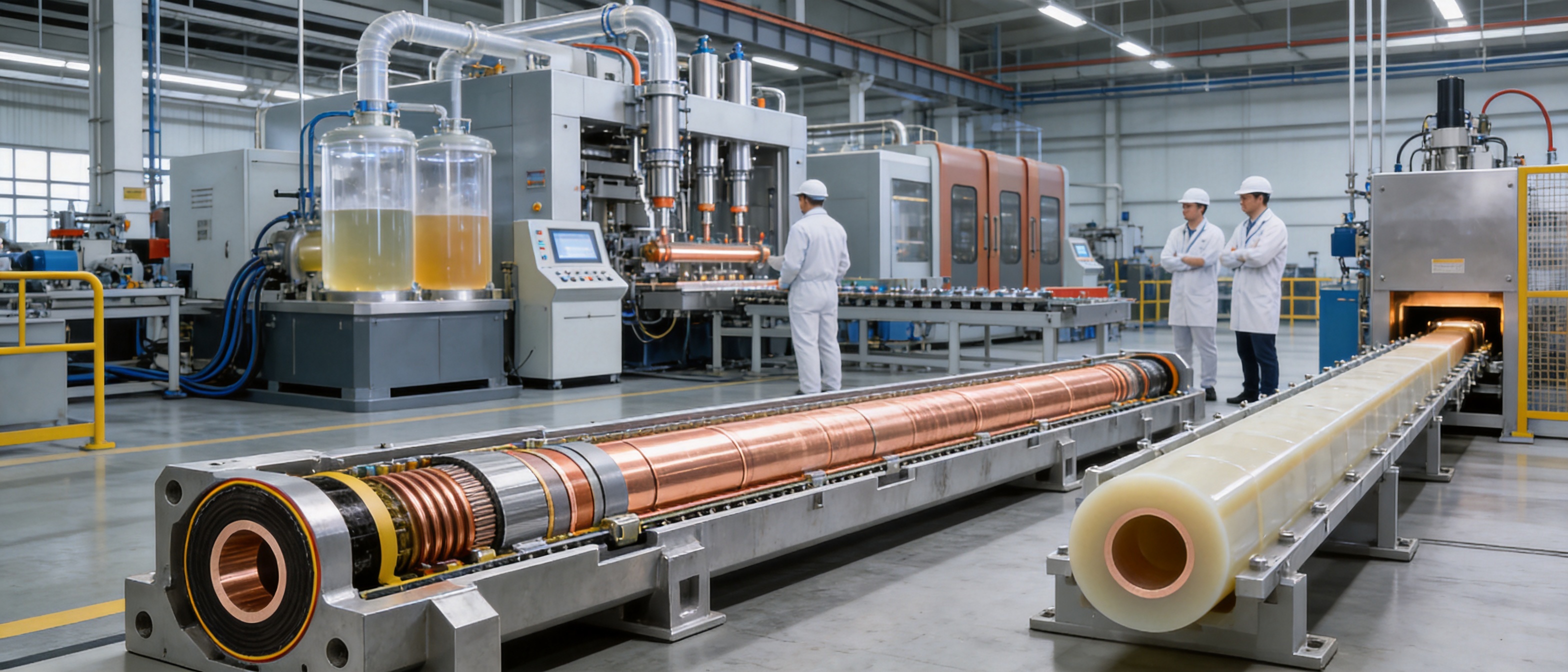
The most common application is the direct connection between the low-voltage or medium-voltage terminals of a main transformer and the terminals of a switch cabinet. The busbar provides a high-current path with a clean, structured appearance. This arrangement is particularly suitable where the transformer and switchgear are positioned close to one another and a direct connection can reduce routing complexity.
The connection may be fully insulated or configured according to the requirements of the electrical system. Flexible links at the equipment terminals help compensate for alignment tolerances and support a reliable bolted connection.
6.2 Cable Trenches and Cable Mezzanines
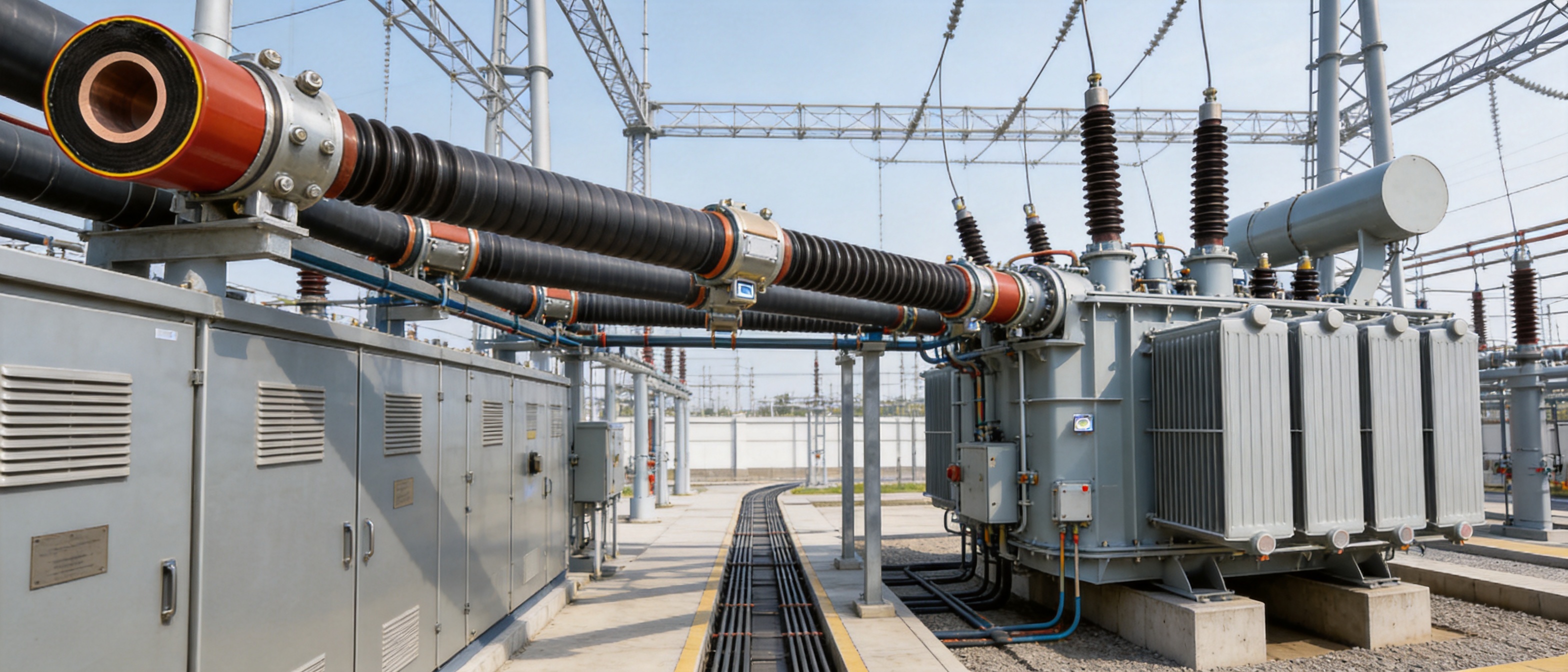
A tubular busbar can be routed through a cable trench or cable mezzanine to connect switchgear and other equipment. This method is useful when direct above-floor routing is not possible or when the project requires a protected, organized path beneath or between electrical rooms.
Because the busbar has a defined tubular geometry, it can be designed to fit within restricted spaces. The installation must account for access, support points, drainage, ventilation, thermal expansion, inspection clearances, and the prevention of water accumulation in the trench.
6.3 Connections Between Switch Cabinets
Where several switch cabinets must be connected, a tubular busbar can provide a compact alternative to numerous cable links. The fully insulated structure helps maintain orderly routing and minimizes exposure to energized parts. This is useful in industrial distribution systems, utility substations, manufacturing plants, and large commercial buildings.
6.4 Renewable Energy Facilities
Wind power and solar power facilities often require equipment that can operate under temperature variation, vibration, humidity, dust, and restricted installation conditions. Tubular busbars can be used in selected collector systems, transformer connections, converter areas, and other high-current sections when the voltage, current, fault level, and environmental requirements are compatible with the product design.
Wind turbine applications require particular attention to vibration, nacelle space, maintenance access, and dynamic loading. The busbar route and support system must be engineered for the turbine structure rather than treated as a conventional static installation.
6.5 Industrial Plants
Petrochemical, metallurgy, mining, manufacturing, and process industries often operate in environments containing dust, humidity, corrosive substances, heat, and mechanical vibration. The sealed cast structure and shielding system can reduce the exposure of the conductor to contamination. The exact resin formulation, external protection, terminal design, and corrosion treatment should be selected according to the atmosphere classification.
6.6 Hospitals, Data Centers, and High-Rise Buildings
Facilities such as hospitals, data centers, and high-rise buildings place strong emphasis on electrical continuity, fire safety, compact installation, and predictable maintenance. The flame-retardant cast insulation and organized routing of tubular busbars can support these objectives. For critical facilities, the system should be coordinated with redundant power architecture, emergency power systems, fire compartments, monitoring equipment, and maintenance procedures.
6.7 Rail Transit and Large Commercial Facilities
Rail transit systems and large commercial complexes require reliable power distribution across areas where space, access, and safety are important. A tubular busbar may be used for transformer connections, distribution sections, traction-related auxiliary systems, or building power infrastructure, subject to the applicable electrical and transportation standards.
7. Typical Installation Arrangements
7.1 Direct Main Transformer Connection
In the direct transformer-to-control-room arrangement, the busbar runs from the transformer terminal to the switch cabinet terminal. This is the most straightforward configuration and is suitable for high-current applications. The route is visually clear and can be planned as a fully insulated connection.
Important design factors include transformer and switchgear alignment, terminal height, phase spacing, flexible connection length, support location, short-circuit forces, and access for inspection. The installation team should verify the final dimensions before manufacturing because the cast tubular sections are produced according to the approved route and connection drawings.
7.2 Cable Trench or Cable Mezzanine Route
In a trench arrangement, the tubular busbar is installed below floor level or within a dedicated cable passage. This can protect the route from accidental contact and leave the main operating floor clear. Drainage and waterproofing are especially important because standing water can damage joints, grounding points, supports, and connected equipment.
The trench should provide sufficient space for installation tools, inspection, thermal dissipation, and future maintenance. Covers, barriers, and ventilation should be coordinated with the busbar’s heat dissipation requirements.
7.3 Upper or Lower Switchgear Connection
Switch cabinets may be connected from their upper cable connection section or through a lower cable connection method. The preferred arrangement depends on the cabinet design, floor layout, transformer position, cable trench arrangement, and maintenance strategy.
Upper connections can simplify overhead routing when the equipment room has sufficient vertical clearance. Lower connections can create a cleaner floor-level arrangement when a cable basement or trench is available. In both cases, the busbar route should avoid unnecessary bends and maintain the manufacturer’s minimum geometric and support requirements.
7.4 Intelligent Monitoring
A tubular busbar monitoring system can be used to collect multiple technical parameters and support unmanned or centralized supervision. Depending on the project design, monitoring may include temperature, grounding continuity, insulation-related information, operating status, and alarm conditions.
Intelligent monitoring is particularly useful for substations, renewable energy facilities, industrial plants, and critical buildings where early detection of abnormal temperature or connection conditions can reduce the risk of unplanned shutdowns. Monitoring devices must be properly insulated, calibrated, protected from electromagnetic interference, and integrated with the site control system.
8. Manufacturing and Engineering Strengths
The performance of a cast tubular busbar depends not only on the resin formulation but also on equipment, process control, engineering design, testing, and field support. Jiangsu Wopeng Power Technology was founded in 2018 as a specialized high-tech enterprise focused on high- and low-voltage busbar systems.
The company’s product portfolio covers systems from low voltage to 35 kV, including 35 kV epoxy resin vacuum-cast tubular busbars, low-voltage epoxy-cast busbar trunking, copper and aluminum tubular busbars, wind power tubular busbars, compact busbar systems, and sliding contact line power supply systems. This range allows the engineering team to compare different busbar technologies and select a suitable solution for the voltage, current, installation, and environmental requirements of a project.
8.1 Automated Vacuum Casting Equipment
Automated vacuum casting equipment improves production repeatability. The dual-component injection process provides controlled resin mixing, while vacuum treatment reduces the likelihood of internal voids. Pressure injection promotes complete mold filling, and high-temperature curing produces the required thermoset structure.
Automation also supports production traceability. Important process data can be recorded and linked to the product identification number, batch, material lot, mold, operator, and inspection results. Such records are valuable for quality management and future service support.
8.2 CNC Machining and Automated Assembly
CNC machining equipment supports accurate preparation of conductor ends, connection surfaces, joint components, and mechanical parts. Dimensional accuracy is important because a small alignment error can affect the connection to a transformer or switchgear terminal.
Automated assembly technologies help standardize the installation of shielding layers, grounding components, protective parts, and hardware. Consistent assembly reduces variation between products and supports stable electrical and mechanical performance.
8.3 Engineering Customization
Tubular busbar systems are rarely identical from one project to another. Transformer terminal positions, switchgear dimensions, voltage level, current rating, route length, support spacing, seismic requirements, and environmental conditions all influence the design.
A capable manufacturer should be able to develop customized drawings, connection arrangements, conductor dimensions, insulation thicknesses, shielding configurations, support details, and monitoring options. Customization should be completed through a controlled engineering process that includes site data review, interface verification, three-dimensional or detailed route planning where necessary, design approval, and manufacturing release.
8.4 Quality Management
A strict quality management system should cover material acceptance, process inspection, final testing, packaging, transportation, and installation support. The manufacturer’s stated inspection activities include high-voltage tests, insulation tests, mechanical verification, and routine quality checks.
Third-party testing collaboration can provide independent verification for type testing or project-specific requirements. For major power projects, purchasers should request the applicable test reports, inspection plans, quality certificates, drawings, installation instructions, and maintenance recommendations before final approval.
Wopeng products operate across more than 17 provinces and key industrial sectors, demonstrating experience with different climate zones, industrial conditions, and project environments. This field experience can help the manufacturer identify practical installation issues and improve the design of customized busbar systems.
9. Design and Selection Guidelines
9.1 Voltage Level
The rated voltage determines the required insulation thickness, shielding arrangement, terminal design, creepage distance, and testing requirements. The reference insulation thicknesses provided for 10 kV, 35 kV, 66 kV, 110 kV, and 220 kV are useful for preliminary planning, but the final value must be confirmed through insulation coordination and the approved product design.
9.2 Rated Current and Temperature Rise
The rated current affects conductor diameter, wall thickness, heat dissipation, joint design, support arrangement, and monitoring requirements. A standard product may carry up to 3,500 A according to the provided product information, while larger current ratings may be customized.
Current rating should not be selected only from the conductor cross-section. Ambient temperature, enclosure conditions, altitude, installation orientation, spacing between phases, thermal radiation, joint resistance, and continuous or intermittent loading must all be considered. Short-circuit current and duration must also be specified because electromagnetic forces can be much higher during a fault than during normal operation.
9.3 Route and Support Design
The busbar route should be as direct as practical while maintaining the required clearances and access. The design should identify all bends, offsets, terminal elevations, support locations, expansion points, and connection interfaces before production.
The maximum suspended span is stated as no more than 5 meters for the relevant product configuration. Longer routes may require additional supports, structural analysis, or a different arrangement. Support hardware must withstand the weight of the busbar, installation loads, wind loads where applicable, seismic forces, and short-circuit electrodynamic forces.
9.4 Equipment Interfaces
The connection between the tubular busbar and electrical equipment is made using flexible links and bolted fastening. Flexible connections help absorb small movement and alignment differences between the rigid busbar and equipment terminals. The conductor contact surfaces must be clean, correctly plated, properly aligned, and tightened to the specified torque.
Terminal design should consider the transformer bushing, switchgear terminal, cable box, phase arrangement, grounding clearance, and maintenance space. Interface drawings should be reviewed jointly by the busbar manufacturer, transformer supplier, switchgear supplier, and project engineering team.
9.5 Environmental Protection
For outdoor or semi-outdoor installations, the design must consider ultraviolet radiation, rain, condensation, salt, dust, wind, ice, and temperature cycling. External protective layers, terminal covers, heat-shrink components, sealing systems, and drainage must be coordinated with the local conditions.
Metal parts used in field construction should receive anti-rust treatment, and hot-dip galvanized bolts and screws should be used as specified. Protective measures should not interfere with grounding continuity or thermal performance.
10. Installation, Testing, and Maintenance
10.1 Installation Preparation
Before installation, the site team should verify the route, supports, foundation, equipment terminal positions, lifting method, storage conditions, and access. Cast resin components should be protected from impact, excessive bending, contamination, and unauthorized drilling or modification.
The product should be inspected for visible cracks, damage, contamination, loose hardware, deformation, and missing identification marks. Any discrepancy should be recorded and reported before energization or field modification.
10.2 Joint Installation
Intermediate joints and terminal connections must follow the manufacturer’s installation instructions. Conductor surfaces should be prepared as specified, and plated contact surfaces should not be damaged. Bolts should be tightened using calibrated tools and the specified sequence.
Grounding leads must be connected securely to the metal shield and the site grounding system. Grounding points should remain identifiable after installation. Waterproofing and moistureproofing materials must be installed correctly around the grounding screen and terminal areas.
10.3 Electrical Tests
Before energization, the completed busbar system should undergo the required insulation resistance, withstand-voltage, conductor resistance, grounding continuity, phase identification, and visual inspections. Test voltage and procedure must follow the approved technical documents and applicable standards.
Where required, partial discharge testing, temperature monitoring verification, and shield continuity checks may be conducted. Test results should be documented and compared with the acceptance criteria established for the project.
10.4 Routine Maintenance
The integrated insulation body generally requires less routine maintenance than exposed busbars, but the complete system still requires periodic inspection. Maintenance personnel should check terminal bolts, grounding connections, protective covers, support hardware, signs of overheating, contamination, corrosion, water accumulation, and abnormal vibration.
Thermal imaging can help identify high-resistance joints or overloaded sections during operation. If a joint shows an abnormal temperature rise compared with the conductor body or adjacent phases, the equipment should be investigated according to the site safety procedure.
11. Why This Product Can Outperform Competing Solutions
The main competitive advantage of Epoxy Resin Casting Tubular Bus Bar is the combination of integrated insulation, high-conductivity copper, reliable joint technology, mechanical rigidity, shielding, grounding, and automated manufacturing. Some competing products may offer one or two of these features, but the value of this system comes from how the features work together.
Compared with basic cable systems, the product can reduce the number of parallel conductors and simplify high-current routing. Compared with open conductors, it provides greater protection from accidental contact and environmental contamination. Compared with loosely assembled insulated busbars, the vacuum-cast structure reduces internal interfaces and creates a more rigid and stable body.
The manufacturing process is also a differentiator. Automated two-component vacuum injection, pressure filling, and high-temperature curing provide a more controlled alternative to manual insulation assembly. CNC machining and automated assembly improve dimensional accuracy and repeatability. Standardized inspection and third-party testing cooperation further support project confidence.
Another advantage is engineering flexibility. The product can be adapted to different voltage levels, conductor sizes, route configurations, terminal arrangements, environmental conditions, and monitoring requirements. A manufacturer with experience in copper and aluminum tubular busbars, compact busbars, cast-resin systems, and sliding contact lines can evaluate the entire power transmission problem rather than offering only one fixed product.
In demanding applications, the lowest purchase price does not always represent the lowest total cost. A compact, factory-engineered busbar can reduce site installation work, support requirements, cable termination quantities, and long-term exposure to maintenance problems. The final economic benefit depends on the project layout, current rating, route length, labor costs, civil works, and service requirements.
12. Frequently Asked Questions
Q1: What is an Epoxy Resin Casting Tubular Bus Bar used for?
It is used to transmit electrical power between major components such as transformers, switchgear, control cabinets, generators, and distribution equipment. Typical applications include substations, industrial plants, renewable energy facilities, high-rise buildings, hospitals, data centers, rail transit systems, and large commercial projects.
Q2: What conductor material is used?
The described product uses TZ7 or higher-grade oxygen-free copper, with a stated copper content of at least 99.90 percent for the pure copper tube. Copper or aluminum tubular busbar alternatives may also be available within the manufacturer’s broader product range. The selected material should match the required conductivity, current rating, weight, cost, and project specification.
Q3: What voltage levels are available?
The provided insulation reference table includes 10 kV, 35 kV, 66 kV, 110 kV, and 220 kV configurations. The company’s stated product portfolio particularly includes 35 kV epoxy resin vacuum-cast tubular busbars and low-voltage systems. Availability, insulation thickness, testing, and terminal design must be confirmed for each project.
Q4: What is the expected service life?
The product is designed for a service life of more than 30 years. Another product reference indicates a possible service life of 30 to 40 years under normal working conditions. Actual service life depends on electrical loading, temperature, moisture, pollution, mechanical stress, installation quality, and maintenance.
Q5: Can the busbar be installed outdoors?
Outdoor use may be possible when the product configuration includes suitable protection against ultraviolet radiation, rain, condensation, pollution, corrosion, wind, and ice. Outdoor terminals require careful creepage, sealing, shielding, and grounding design. The manufacturer should confirm the suitability of the selected model for the local environmental conditions.
Q6: What is the maximum current-carrying capacity?
Standard models can carry up to approximately 3,500 A according to the provided product information, while higher-current versions may be customized. The final rating must consider conductor size, ambient temperature, altitude, installation arrangement, thermal conditions, joint performance, and short-circuit requirements.
Q7: Why is vacuum casting important?
Vacuum casting helps reduce air voids and supports more complete resin filling around the conductor and shielding layers. This improves insulation consistency and helps reduce the risk of localized electrical stress. Pressure injection and high-temperature curing further support a dense, mechanically stable insulation structure.
Q8: How are the joints connected?
Insulation joints and copper conductors are formed in one molding operation. Intermediate connections use embedded stainless steel clamp welding. Connections between the busbar terminal joint and equipment use flexible links with bolted fastening. Copper tube ends should be rounded, and their contact surfaces may be silver-plated or tin-plated to help achieve low contact resistance and corrosion resistance.
Q9: How is the metal shield grounded?
The grounding lead is reliably welded to the metal shielding layer using copper stranded or braided conductors. Grounding points must be securely connected to the site grounding system, protected against moisture, and clearly marked and numbered. Continuity should be verified during installation testing.
Q10: What is the maximum suspended span?
The stated maximum suspended span for the vacuum epoxy resin casting tubular busbar is not more than 5 meters. The actual support spacing must be confirmed through mechanical calculations based on the busbar weight, route, seismic conditions, wind, ice, and short-circuit forces.
Q11: Does the product require extensive maintenance?
The integrated cast structure reduces the number of exposed and detachable insulation components, which can reduce routine maintenance. However, operators should periodically inspect joints, grounding points, supports, protective covers, signs of overheating, corrosion, moisture, and abnormal vibration. Thermal imaging and electrical tests may be included in the maintenance program.
Q12: What information should be supplied when requesting a quotation?
Important information includes rated voltage, rated current, short-circuit current and duration, conductor material, route length, phase arrangement, terminal dimensions, transformer and switchgear drawings, indoor or outdoor installation, altitude, ambient temperature, humidity, pollution level, seismic requirements, support arrangement, monitoring requirements, and applicable standards.
13. Conclusion
Epoxy Resin Casting Tubular Bus Bar is a highly integrated solution for safe and reliable power transmission. Its vacuum-cast epoxy insulation, high-purity copper conductor, embedded joint technology, full shielding, grounding system, moisture protection, and rigid tubular construction address many of the limitations associated with open busbars, complex cable groups, and less integrated insulation arrangements.
The product is particularly valuable where high current, compact routing, fire safety, mechanical strength, environmental resistance, and long service life are required. Its performance is supported by a controlled manufacturing process that combines automated two-component resin preparation, vacuum injection, pressure filling, high-temperature curing, CNC machining, automated assembly, and standardized testing.
Jiangsu Wopeng Power Technology combines product development, manufacturing, engineering customization, and quality control to provide busbar systems for substations, power generation, renewable energy, industrial manufacturing, rail transit, and large commercial infrastructure. By selecting the correct conductor, insulation thickness, joint arrangement, shielding system, support design, and monitoring configuration, project owners can create a durable and maintainable connection between critical electrical equipment.
Final selection should always be based on approved technical drawings, insulation coordination, thermal calculations, short-circuit analysis, environmental assessment, installation requirements, and applicable national or international standards. When these factors are properly addressed, an epoxy resin casting tubular busbar can provide a compact, stable, and dependable foundation for modern medium- and high-current power distribution systems.
References
1. Jiangsu Wopeng Power Technology Co., Ltd., Product Technical Information for Epoxy Resin Casting Tubular Bus Bar.
2. Technical requirements for vacuum epoxy resin casting tubular busbar structure, materials, shielding, grounding, joints, and environmental conditions.
3. IEC 61439, Low-Voltage Switchgear and Controlgear Assemblies.
4. IEC 62271 Series, High-Voltage Switchgear and Controlgear.
5. IEC 60071 Series, Insulation Coordination.
6. IEC 60270, High-Voltage Test Techniques and Partial Discharge Measurements.
7. IEC 60502 Series, Power Cables with Extruded Insulation and Their Accessories.
8. UL 94, Tests for Flammability of Plastic Materials for Parts in Devices and Appliances.
9. GB/T 5582, Classification of Atmospheric Environmental Conditions for Electrical and Electronic Products.
10. General engineering practices for high-current busbar systems, transformer connections, switchgear interfaces, grounding, thermal design, and seismic installation.
Product: Epoxy Resin Casting Tubular Bus Bar




-
 +86-180 3625 3000
-
 admin@wpbusbar.com
-
 No. 8, Yanjin Road, Chengxi Industrial Park, Shanyang Town, Baoying County, Yangzhou City, Jiangsu Province, China
Copyright © Jiangsu Wopeng Power Technology Co., Ltd.
All Rights Reserved.
 Custom Insulated Bus Bar Manufacturer
Tubular Busbar System Factory
Custom Insulated Bus Bar Manufacturer
Tubular Busbar System Factory