

 EN

 English
 русский
 Français
 Español
 عربى

PTFE Tubular Bus Bar: Advanced Insulation for Extreme-Environment Power Transmission
Content
- 1 1. Overview of PTFE Tubular Bus Bar Technology
- 2 2. Structural Composition
- 3 3. Main Technical Advantages
- 4 4. Comparison with Conventional Insulated Bus Bars
- 5 5. Advanced Manufacturing Process
- 5.1 5.1 Engineering and Product Design
- 5.2 5.2 Conductor Preparation
- 5.3 5.3 Precision PTFE Winding
- 5.4 5.4 Bubble Control and Silicone Oil Application
- 5.5 5.5 Surface Treatment and Layer Stability
- 5.6 5.6 Installation of Capacitive Screens
- 5.7 5.7 Creepage Extender Assembly
- 5.8 5.8 Sealing, Termination and Final Assembly
- 6 6. Quality Control and Testing
- 7 7. Manufacturing Strengths and Engineering Capability
- 8 8. Typical Application Solutions
- 9 9. Design and Selection Considerations
- 10 10. Limitations and Engineering Challenges
- 11 11. Service Life and Reliability
- 12 12. Frequently Asked Questions
- 12.1 Q1: What is a PTFE tubular bus bar?
- 12.2 Q2: Why is PTFE used for tubular bus bar insulation?
- 12.3 Q3: What temperature range can the product withstand?
- 12.4 Q4: Can the tubular bus bar be customized?
- 12.5 Q5: Is the product suitable for outdoor use?
- 12.6 Q6: How does it compare with an epoxy resin cast bus bar?
- 12.7 Q7: What tests should be requested before delivery?
- 12.8 Q8: What conductor materials are available?
- 12.9 Q9: How should the product be maintained?
- 12.10 Q10: Why is manufacturing experience important?
- 13 13. Conclusion
- 14 References
- 15 Product: PTFE Tubular Bus Bar
Reliable power transmission depends on more than conductor size and current-carrying capacity. In demanding installations, the insulation system, environmental resistance, mechanical stability, heat management and manufacturing quality are equally important. A bus bar may be exposed to high voltage, temperature fluctuations, moisture, salt spray, industrial chemicals, vibration and limited maintenance access. Under these conditions, conventional insulation systems may experience accelerated aging, surface contamination, thermal stress or reduced dielectric performance.
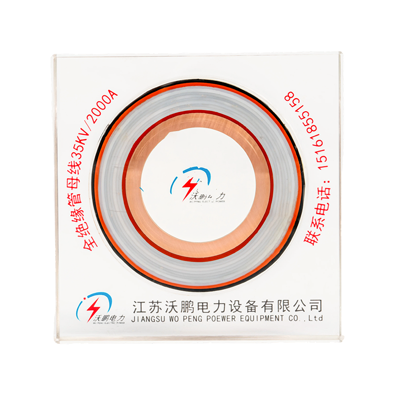
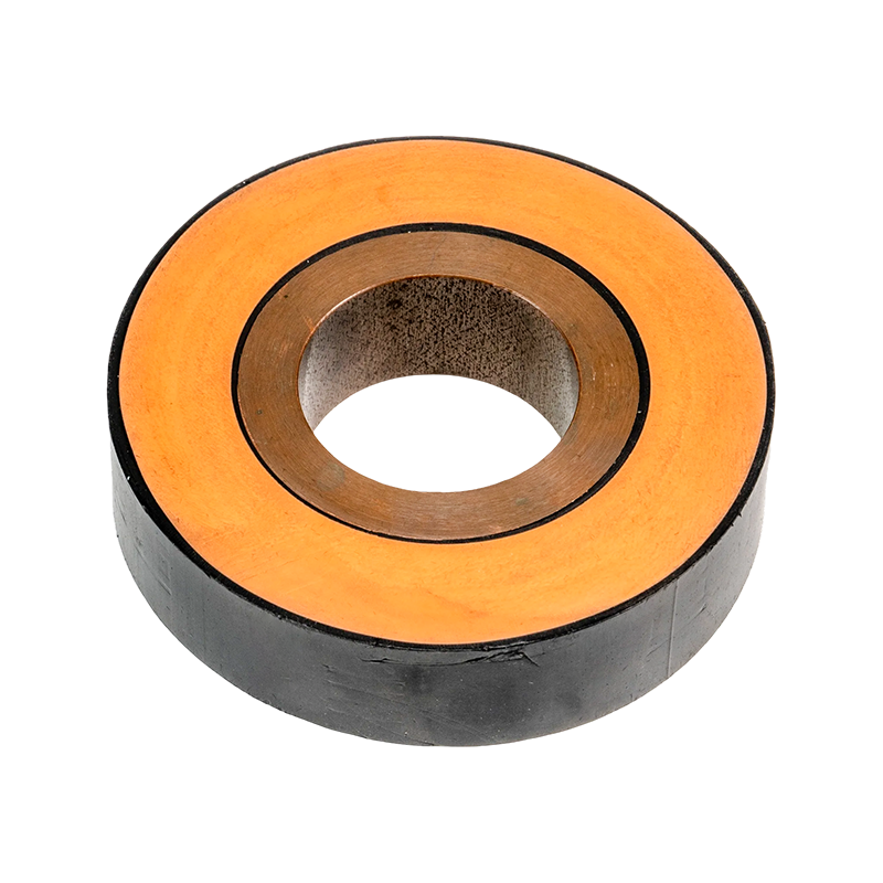
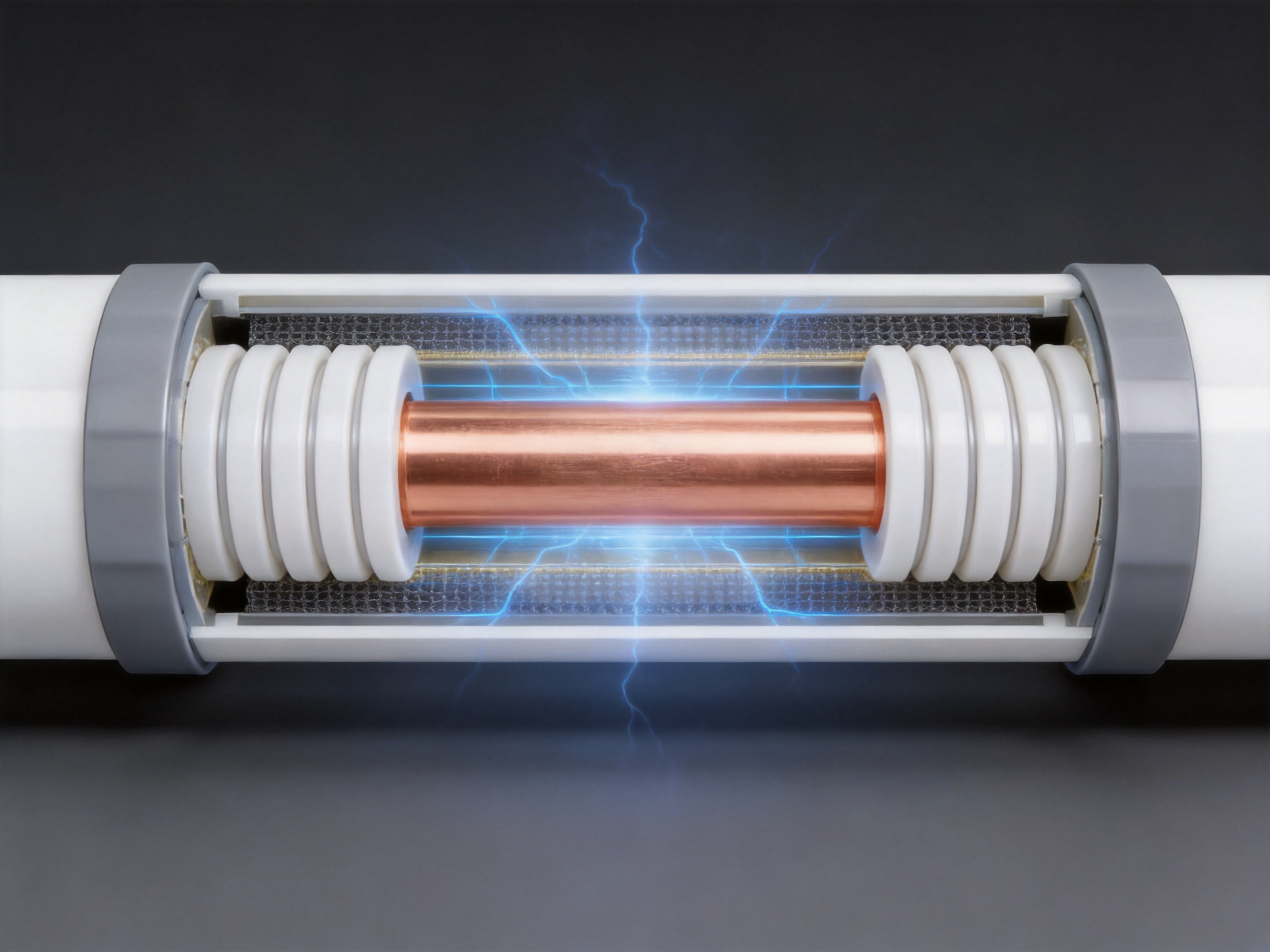
PTFE tubular bus bar technology is designed to address these challenges. It combines a copper or aluminum conductive tube with a precisely formed polytetrafluoroethylene insulation system, capacitive screens and silicone rubber creepage extenders. The resulting structure provides high dielectric strength, strong resistance to corrosion, stable operation over a wide temperature range and protection suitable for demanding indoor and outdoor applications.
This article explains the structure, operating principles, technical advantages, manufacturing process, application methods and selection considerations of PTFE tubular bus bars. It also examines how advanced production capabilities, engineering experience and quality control contribute to dependable performance in modern power systems.
1. Overview of PTFE Tubular Bus Bar Technology
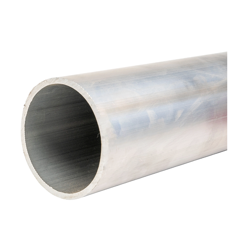
A PTFE tubular bus bar is an insulated power transmission component consisting primarily of a metal conductor, a PTFE-based insulation system and an external protective structure. The conductor may be manufactured from copper or aluminum, depending on the required current rating, weight, conductivity, mechanical strength and project budget.
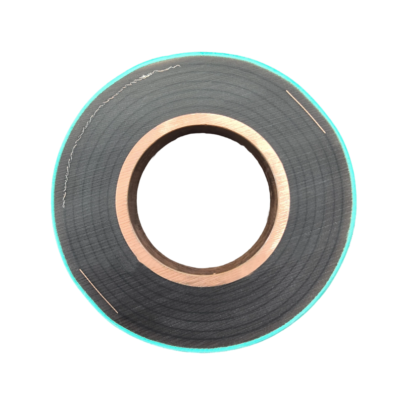
The insulation is formed by mechanically winding PTFE film around the conductor. During the winding process, silicone oil is applied between layers to create a dense, continuous and gas-free insulating structure. This process is important because air voids, uneven tension and poorly bonded layers can create local electric field concentration. By controlling the winding conditions, the insulation system can maintain more uniform dielectric performance along the entire bus bar length.
The product can also incorporate at least five capacitive screens. Depending on the design, these may include a zero screen, grading screens and a grounding screen. The screens help control the electric field, reduce localized voltage stress and improve the stability of the insulation system under high-voltage operating conditions.
Silicone rubber creepage extenders are installed where necessary to increase the surface creepage distance. This is particularly valuable in humid, polluted, dusty or salt-laden environments, where surface leakage can become a major concern. The combination of PTFE insulation, field-control screens and creepage extenders creates a comprehensive protection system rather than relying on insulation thickness alone.
2. Structural Composition
2.1 Metal Conductor Core
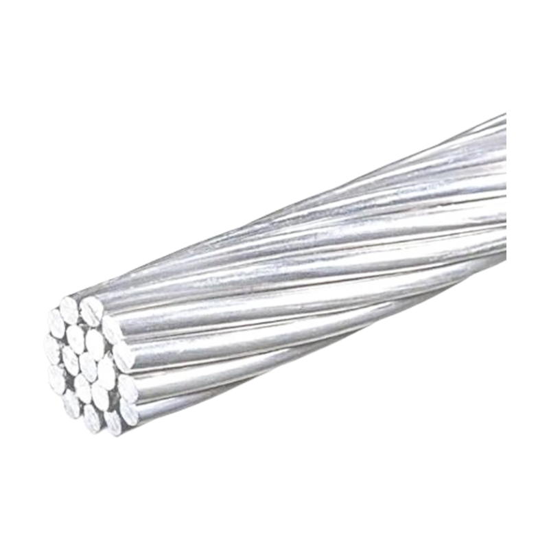
The conductor core is the primary current-carrying element. Copper is often selected where maximum conductivity, compact dimensions and high short-circuit strength are required. Aluminum may be selected when low weight, cost efficiency and simplified handling are priorities.
The conductor geometry can be adjusted according to the rated current, installation length, voltage class, thermal conditions and connection method. Tubular conductors provide a practical balance between electrical performance and mechanical rigidity. Their hollow or tubular construction can also support weight reduction compared with an equivalent solid conductor, depending on the selected design.
Conductor surfaces must be properly prepared before insulation winding. Dimensional accuracy, surface cleanliness, roundness and absence of sharp edges are important because irregularities can damage the PTFE film or create local stress concentrations. Advanced production lines therefore include machining, cleaning, inspection and controlled assembly operations before the insulation process begins.
2.2 PTFE Film Insulation
PTFE is selected for its combination of electrical stability, chemical inertness, low friction and wide operating temperature capability. It offers a low dielectric constant and low dielectric loss, which helps limit electrical losses and support stable insulation performance.
The PTFE insulation is applied through mechanical winding rather than simple loose wrapping. Each layer must be positioned accurately, with controlled overlap and consistent tension. The supplied technical requirements specify inter-layer tension uniformity within approximately plus or minus two percent. This level of control helps prevent wrinkles, gaps, excessive compression and uneven dielectric thickness.
Because PTFE has very low surface energy, it is naturally resistant to bonding. This characteristic is advantageous for chemical resistance and low friction, but it creates a manufacturing challenge when multiple layers must remain stable. Special surface treatment agents and carefully controlled process conditions may be used to improve inter-layer adhesion and structural integrity.
2.3 Silicone Oil and Gas-Free Insulation
Silicone oil is applied between PTFE layers to help form a dense, gas-free continuous insulation system. The elimination or reduction of internal air pockets is essential in high-voltage equipment. Air has a lower dielectric strength than PTFE and may support partial discharge when subjected to an intense electric field.
Ultrasonic assistance can be used during winding to help control bubbles and improve the continuity of the insulation. Process monitoring is required to maintain a consistent application rate and prevent contamination. A stable inter-layer structure improves dielectric reliability and reduces the likelihood of localized insulation degradation.
2.4 Capacitive Screens
High-voltage tubular bus bars may incorporate several capacitive screens to guide the electric field. The screens are arranged within the insulation structure so that voltage distribution is more gradual from the conductor toward the grounded outer layer.
A zero screen, grading screens and a grounding screen can work together to reduce electric field concentration at interfaces, joints and terminations. The exact screen arrangement depends on the voltage level, conductor geometry, insulation thickness and connection design.
Field grading is particularly important at the ends of a bus bar. Terminations can experience greater electrical stress because the geometry changes rapidly and the electric field may spread outward. Proper screening and the use of creepage extenders help maintain predictable performance at these critical locations.
2.5 Silicone Rubber Creepage Extenders
Silicone rubber creepage extenders increase the distance that a leakage current must travel along the insulation surface. This is different from clearance, which is the shortest distance through air. In polluted or wet environments, a longer creepage path helps reduce the risk of surface tracking and flashover.
Silicone rubber is useful in this application because it offers flexibility, weather resistance and good performance across a broad temperature range. Its surface properties can also support hydrophobic behavior, helping reduce the formation of continuous conductive moisture films under some environmental conditions.
3. Main Technical Advantages
3.1 Wide Temperature Capability
One of the most important benefits of PTFE tubular bus bar technology is its resistance to temperature extremes. The product is designed for an operating temperature range extending from approximately minus 60 degrees Celsius to 250 degrees Celsius in the specified extreme-environment configuration.
This capability supports applications in cold regions, high-temperature industrial areas, outdoor substations, special process facilities and locations exposed to rapid temperature changes. The insulation system is less likely to become brittle at low temperature or lose stability during high-temperature operation when compared with insulation systems that have a narrower thermal range.
Actual temperature ratings should always be confirmed for the complete assembly, including the conductor, joints, terminals, screens, support structures and installation conditions. Some configurations or related tubular bus bar designs may use a working range of minus 60 degrees Celsius to 200 degrees Celsius. A project-specific technical review is therefore necessary before final selection.
3.2 Strong Corrosion Resistance
PTFE is highly resistant to acids, alkalis, salt spray and many organic solvents. This makes PTFE tubular bus bars suitable for coastal facilities, chemical plants, industrial workshops, wastewater-related infrastructure and other areas where conventional insulation may be attacked by contaminants.
Corrosion resistance has both immediate and long-term value. It helps preserve the physical integrity of the insulation and reduces the frequency of cleaning, repair and replacement. It also allows the bus bar to maintain stable electrical performance in environments where moisture and corrosive gases are difficult to eliminate.
Although PTFE is chemically resistant, the conductor, screen connections and metallic fittings still require appropriate material selection and surface protection. Corrosion protection must therefore be considered for the complete bus bar system, not only the PTFE insulation.
3.3 High Dielectric Strength
The reported dielectric strength of the PTFE insulation is approximately 35 kV per millimeter or higher, depending on the material, thickness and test conditions. This provides a significant electrical safety margin when the insulation system is correctly designed and manufactured.
High dielectric strength enables the bus bar to withstand strong electric field gradients while maintaining a compact structure. The use of capacitive screens further improves field distribution and reduces the possibility of localized overstress.
Dielectric performance depends on more than the nominal breakdown value. Layer uniformity, air voids, contamination, end geometry, termination design, partial discharge behavior and mechanical damage all influence practical service reliability. For this reason, controlled production and comprehensive testing are essential.
3.4 Low Dielectric Loss
PTFE has a low dielectric constant and low dielectric loss. A low loss factor, specified in the supplied technical information as no greater than approximately 0.0002 at 50 Hz, helps minimize energy dissipation in the insulation system.
Reduced dielectric loss can be beneficial in long bus bar runs and high-voltage applications where even small losses may accumulate over time. Lower heat generation also supports improved thermal stability, although conductor resistance and load current remain the primary factors in overall bus bar heating.
3.5 Low Friction and Reduced Mechanical Stress
PTFE has an extremely low coefficient of friction. This characteristic can reduce mechanical resistance between insulation layers and support controlled movement caused by thermal expansion and contraction.
Thermal cycling can create stress in rigid insulation systems. A PTFE film structure with suitable flexibility may accommodate small dimensional changes more effectively than materials that are highly rigid or brittle. The design must nevertheless account for expansion, support spacing, vibration and connection movement to prevent mechanical damage.
3.6 High Environmental Protection
With suitable sealing, external protection and termination design, PTFE tubular bus bars can achieve protection levels reaching IP68. This level of protection is valuable where the equipment may be exposed to dust, water, temporary immersion or difficult cleaning conditions.
IP protection is determined by the complete product configuration. Joints, inspection points, end fittings and cable interface areas must be sealed to the same standard as the main body. Project engineers should confirm the exact protection rating for the supplied assembly and installation method.
4. Comparison with Conventional Insulated Bus Bars
PTFE tubular bus bars are not the only insulated bus bar solution. Epoxy resin casting, silicone rubber insulation, air-insulated bus bars and other polymer systems may be suitable for specific applications. The correct choice depends on voltage, current, environment, installation space, maintenance requirements and project economics.
| Performance Item | PTFE Tubular Bus Bar | Epoxy Resin Cast Bus Bar | Silicone Rubber Insulated Bus Bar |
|---|---|---|---|
| Typical dielectric strength | Approximately 35 kV/mm or higher | Approximately 30 kV/mm or higher | Approximately 25 kV/mm or higher |
| Typical temperature range | Approximately -60°C to 200°C or up to 250°C, depending on configuration | Approximately -30°C to 130°C | Approximately -40°C to 120°C |
| Dielectric loss | Approximately 0.0002 or lower at 50 Hz | Approximately 0.001 | Approximately 0.0005 |
| Chemical resistance | Excellent against many acids, alkalis, salts and solvents | Good, depending on resin formulation | Good, but dependent on chemical exposure |
| Flexibility | Good film-layer flexibility | Low to moderate after curing | High flexibility |
| Extreme-temperature suitability | Excellent | Moderate | Moderate to good |
| Manufacturing complexity | High precision winding and screening required | Vacuum casting and curing control required | Extrusion or molding process control required |
The comparison demonstrates why PTFE is attractive for severe environments. Its temperature capability and chemical resistance are particularly strong. It also provides low dielectric loss and high dielectric strength when the winding and screening process is properly controlled.
However, technical superiority in one category does not automatically make PTFE the best choice for every project. PTFE material and processing costs are higher than those of many conventional insulation systems. It also presents recycling and environmental processing challenges because PTFE is difficult to degrade. For ordinary indoor installations with moderate environmental stress, a lower-cost insulation system may be more economical.
The strongest application case for PTFE tubular bus bar is where the cost of failure, environmental exposure or maintenance access justifies the higher initial investment.
5. Advanced Manufacturing Process
5.1 Engineering and Product Design
Manufacturing begins with engineering analysis. The design team reviews the rated voltage, continuous current, short-circuit current, installation route, support span, ambient temperature, pollution level, altitude, moisture exposure, connection method and required protection rating.
Electrical field analysis is used to determine insulation thickness, screen locations and termination geometry. Thermal calculations evaluate conductor temperature rise and heat dissipation. Mechanical calculations address weight, support loads, vibration, expansion and short-circuit forces.
For custom products, the engineering team can adapt the conductor size, insulation thickness, screen configuration, terminal structure, mounting method and overall length. Customization is especially important when the bus bar must connect directly to transformers, switchgear, generators or specialized industrial equipment.
5.2 Conductor Preparation
Copper or aluminum conductor material is cut and machined according to the approved drawings. Dimensional tolerances are controlled to ensure that the conductor can receive a uniform insulation layer. Connection surfaces are finished to provide reliable electrical contact at terminals and joints.
Before winding, the conductor is inspected for burrs, sharp edges, dents, contamination and dimensional variation. Cleaning removes oil, dust and metallic particles that could interfere with the PTFE insulation or reduce dielectric reliability.
5.3 Precision PTFE Winding
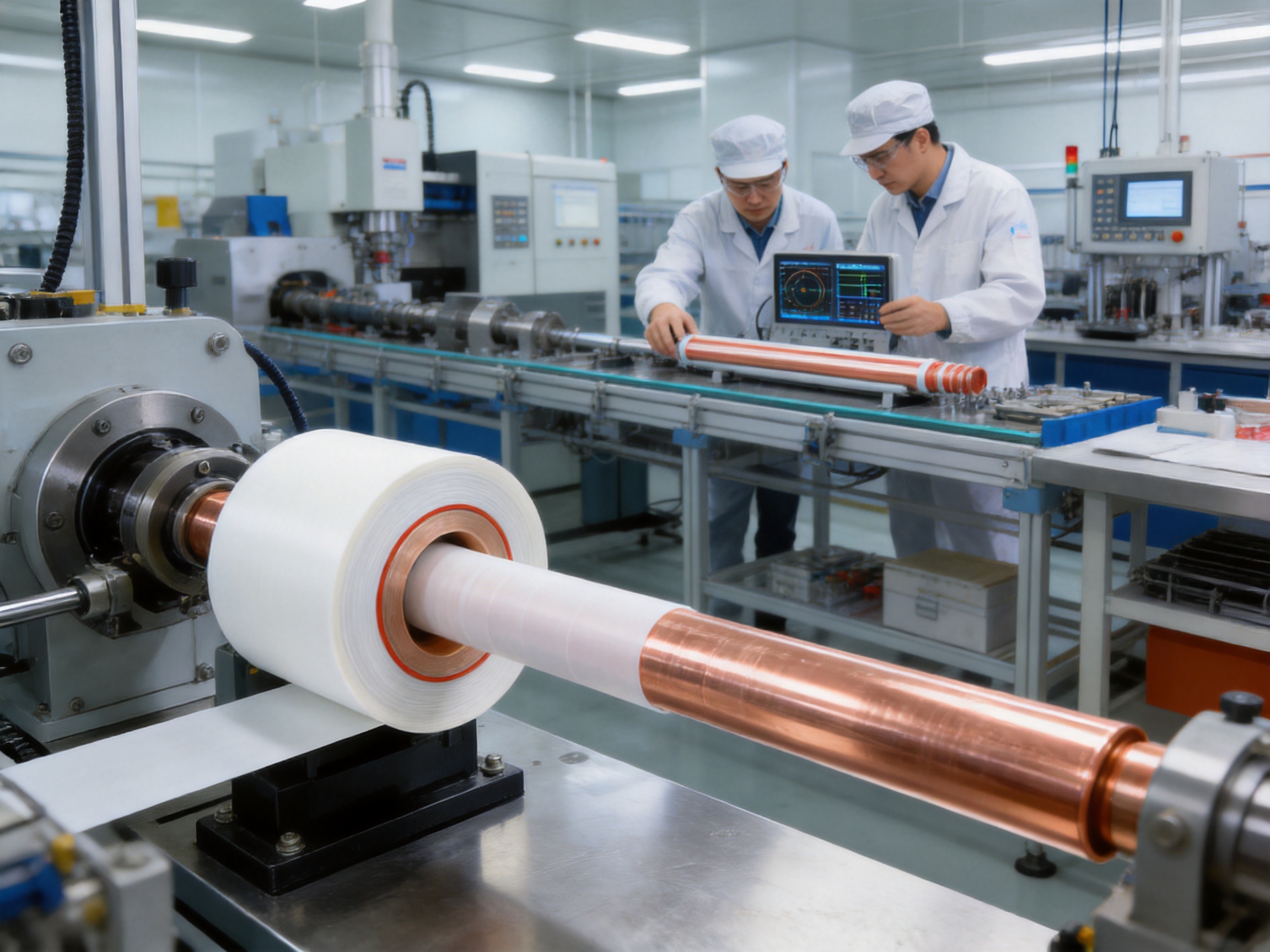
The PTFE film winding stage is the central process of the product. Specialized equipment controls the film feed, winding speed, overlap, angle and tension. Automated or semi-automated systems help maintain repeatability across long production runs.
Inter-layer tension is carefully monitored because excessive tension may compress the insulation or damage the film, while insufficient tension may create folds and voids. The specified process target calls for tension uniformity within approximately plus or minus two percent.
Winding conditions are adjusted according to film width, conductor diameter, insulation thickness and product length. Operators and process engineers inspect the winding surface for wrinkles, gaps, foreign particles and other defects. Any irregularity must be corrected before the next production stage.
5.4 Bubble Control and Silicone Oil Application
Silicone oil is introduced between PTFE layers to assist the formation of a dense, gas-free insulating structure. The application system must maintain stable flow and distribution throughout the winding operation.
Ultrasonic assistance may be used to reduce bubbles and improve inter-layer continuity. Bubble control is important because trapped air can become a site for partial discharge under high voltage. The production area must also be kept clean and controlled to prevent dust, moisture and other contaminants from entering the insulation system.
5.5 Surface Treatment and Layer Stability
PTFE has a low surface energy, which means that ordinary adhesives do not bond easily to it. Where structural layer stability is required, special treatment agents or surface activation processes may be applied.
These treatments must be carefully selected so that they do not reduce the chemical, thermal or electrical properties of the final product. Process records should document treatment type, application quantity, curing or drying conditions and inspection results.
5.6 Installation of Capacitive Screens
Capacitive screens are installed at defined locations within the insulation structure. Their dimensions, overlap and electrical connections must conform to the design requirements.
Screen continuity and grounding paths are checked before the final protective layers are applied. Incorrect screen placement can produce undesirable electric field concentrations, so this stage requires strict process discipline and traceability.
5.7 Creepage Extender Assembly
Silicone rubber creepage extenders are fitted at designated positions, especially near terminals and areas exposed to contamination. Their shape and spacing are designed to increase surface leakage distance without interfering with installation or maintenance.
The extenders must be securely fixed and free from cuts, voids and surface contamination. Their compatibility with the PTFE insulation, metal fittings and environmental conditions is also reviewed.
5.8 Sealing, Termination and Final Assembly
Termination design is critical because electrical, mechanical and environmental stresses are concentrated at the ends of a bus bar. The termination must provide reliable electrical contact, smooth field grading, adequate creepage distance and effective sealing.
Final assembly may include metal end fittings, grounding points, support interfaces, protective covers and connection hardware. Each component is checked for alignment and dimensional accuracy before the product is released for testing.
6. Quality Control and Testing
6.1 Incoming Material Inspection
Quality control begins with inspection of incoming materials. PTFE film is checked for thickness, surface condition, dimensional stability and visual defects. Copper and aluminum conductors are examined for composition, conductivity, dimensions and surface quality.
Silicone rubber components, oils, screen materials and metallic fittings are also inspected against the applicable specifications. Traceability records ensure that materials can be connected to specific production batches.
6.2 Process Inspection
Process inspection is performed during conductor preparation, PTFE winding, silicone oil application, screen installation and final assembly. Important parameters include winding tension, overlap, insulation thickness, surface condition, screen continuity and termination dimensions.
Non-destructive inspection methods may be used to identify gaps, delamination, surface defects or dimensional irregularities. Process data provides evidence that the product was manufactured within the approved technical parameters.
6.3 Electrical Testing
High-voltage withstand testing verifies that the insulation can tolerate the specified electrical stress. Insulation resistance testing evaluates the ability of the insulation system to prevent leakage current under the defined test conditions.
Where applicable, partial discharge testing can identify localized defects, voids or field concentrations that may not be detected by a basic withstand test. Capacitance and dielectric loss measurements provide additional information about the integrity and uniformity of the insulation system.
6.4 Mechanical and Environmental Verification
Mechanical verification may include dimensional inspection, terminal strength checks, support interface checks and evaluation of resistance to vibration or handling stress. Environmental verification can include temperature cycling, moisture exposure, salt spray or chemical resistance testing according to project requirements.
Products intended for high-protection applications should also be evaluated for sealing and water ingress resistance. The final test program should be established according to the voltage class, installation environment, customer specifications and applicable standards.
6.5 Third-Party Testing and Technical Validation
Independent testing collaboration can provide additional confidence in product performance. Third-party institutions may verify high-voltage characteristics, insulation performance, mechanical properties and environmental resistance.
Independent validation is particularly useful for major infrastructure projects, utility installations and applications where product failure could cause extended downtime or safety risks. Test reports should be reviewed to confirm that the tested configuration is representative of the proposed project design.
7. Manufacturing Strengths and Engineering Capability
A reliable PTFE tubular bus bar requires more than high-quality raw materials. It depends on integrated engineering, precision production, controlled assembly and disciplined testing. Jiangsu Wopeng Power Technology Co., Ltd. has developed its manufacturing capability around high- and low-voltage bus bar systems and related power transmission equipment.
The company was founded in 2018 and focuses on the development and production of busbar systems for power generation, substations, wind energy, industrial manufacturing, rail transit and large commercial facilities. Its product range includes 35 kV epoxy resin vacuum-cast tubular busbars, low-voltage cast resin busways, copper and aluminum tubular busbars, wind power tubular busbars, compact busbar systems and sliding contact line systems.
This broad product portfolio supports cross-disciplinary engineering experience. Different bus bar technologies require different approaches to insulation, conductor design, mechanical support, thermal performance and installation. Experience across these product categories helps engineers identify practical solutions for complex project conditions.
The manufacturing facility uses vacuum casting systems, CNC machining equipment and automated assembly technologies. CNC equipment supports accurate conductor preparation and fitting production. Vacuum casting capability contributes to the production of epoxy resin products, while automated assembly technologies improve consistency and repeatability across multiple product types.
The company also maintains standardized inspection procedures covering high-voltage tests, insulation tests, mechanical verification and routine quality checks. Cooperation with third-party testing institutions provides independent validation for selected products and performance requirements.
Its products operate across more than 17 provinces and major industrial sectors. This field experience provides practical feedback about installation conditions, environmental exposure, maintenance requirements and system integration. Such feedback can be used to improve product design and support project-specific customization.
8. Typical Application Solutions
8.1 Transformer-to-Switchgear Connection
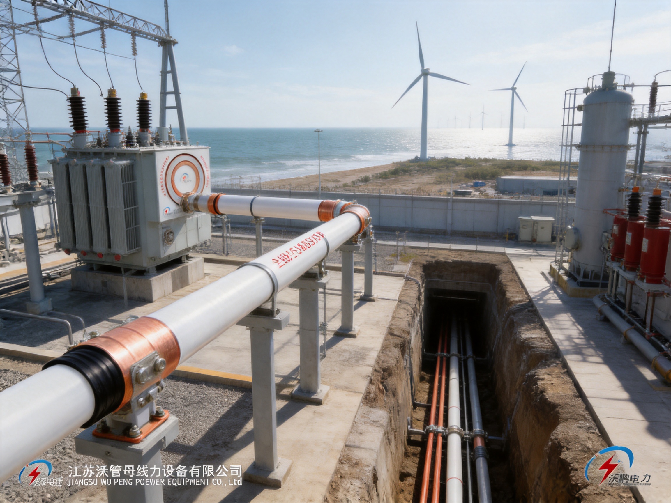
One of the most common applications is the direct connection between the low-voltage terminals of a main transformer and the terminals of a switchgear cabinet or control room. This arrangement is suitable for high-current transmission and can provide a clear, compact and visually organized installation.
A fully insulated tubular bus bar reduces the need for large air clearances and can simplify the routing of high-current conductors. The final design must account for transformer terminal movement, short-circuit forces, support structures, phase spacing, grounding and maintenance access.
8.2 Cable Trench or Cable Mezzanine Routing
Bus bars may be installed through underground cable trenches or cable mezzanines. This method is useful when direct overhead routing is impractical or when the project requires a protected connection between transformers, switchgear and other electrical equipment.
Fully insulated tubular bus bars are well suited to enclosed or difficult-to-access routes. Their sealed structure can help protect the conductor from dust, moisture and accidental contact. The route must nevertheless provide adequate support, drainage, thermal ventilation and access for inspection.
8.3 Switchgear Bottom or Top Connections
In some switchgear installations, the bus bar enters from the top or bottom of the cabinet. The selected direction depends on the equipment layout, cable trench arrangement, transformer position and site construction sequence.
Top-entry and bottom-entry designs require careful coordination of termination dimensions and bending or alignment requirements. A custom manufacturer can develop the bus bar length, interface structure and support arrangement according to the actual switchgear drawings.
8.4 Wind Power and Renewable Energy Facilities
Wind power facilities may require compact, reliable power connections between generators, transformers, converters and collection systems. These installations can experience vibration, temperature changes, humidity and limited maintenance access.
Tubular bus bars designed for wind power applications can be adapted to the available space and mechanical movement. PTFE insulation may be beneficial where wide temperature tolerance, low dielectric loss and chemical resistance are important. The mechanical design must also consider vibration, tower movement and installation logistics.
8.5 Industrial and Chemical Facilities
Industrial plants often contain corrosive gases, solvents, salt deposits, dust and high-temperature equipment. In such environments, the chemical resistance of PTFE provides an advantage over insulation materials that may soften, swell or degrade after prolonged exposure.
The complete system should be evaluated against the actual substances present at the site. Although PTFE resists many chemicals, seals, adhesives, metallic fittings and external protective materials may have different resistance characteristics.
8.6 Coastal and High-Humidity Installations
Coastal substations and marine-adjacent facilities are exposed to salt spray and high humidity. Salt contamination can create a conductive film on insulation surfaces and increase the risk of leakage and tracking.
Long creepage paths, silicone rubber creepage extenders, sealed construction and appropriate maintenance planning help improve performance in these locations. The installation design should include drainage, corrosion-resistant hardware and inspection procedures appropriate for the local pollution level.
9. Design and Selection Considerations
9.1 Voltage Rating
The required voltage rating determines insulation thickness, screen configuration, termination design and testing requirements. The bus bar should be selected according to the highest continuous and transient electrical stress expected in service.
Some technical descriptions associate PTFE tubular bus bars with high-voltage systems ranging from 110 kV to 500 kV, while other tubular bus bar products in the broader portfolio cover systems up to 35 kV. These ranges should not be treated as interchangeable. The actual voltage class depends on the specific product design, test certification and project configuration.
9.2 Current Rating
Current rating depends on conductor material, conductor cross-sectional area, ambient temperature, installation method, permissible temperature rise and ventilation conditions. Aluminum may reduce weight, while copper may allow a smaller conductor for the same current capacity.
Engineers should consider continuous current, overload conditions, short-circuit current and duration. Thermal expansion and connection temperature must also be reviewed because high current produces heat at both the conductor and the joints.
9.3 Installation Environment
Site conditions should be documented before product selection. Important factors include minimum and maximum temperature, humidity, altitude, pollution level, chemical exposure, salt spray, ultraviolet radiation, vibration, flooding risk and available maintenance access.
Where the environment is particularly severe, the product may require additional sealing, specialized external materials, enhanced creepage distance or customized support structures.
9.4 Layout and Interface Requirements
Accurate equipment drawings are required for custom bus bar production. Transformer terminals, switchgear interfaces, support locations, route dimensions, phase arrangement and grounding points should be confirmed before manufacturing begins.
Errors in interface dimensions can delay installation and require field modifications. Early engineering coordination helps reduce these risks and ensures that the bus bar arrives ready for efficient installation.
9.5 Maintenance Strategy
PTFE tubular bus bars can reduce maintenance requirements through their corrosion resistance and sealed construction, but they should not be regarded as maintenance-free. Periodic inspection should verify support condition, termination tightness, grounding continuity, external damage, sealing integrity and signs of contamination.
Inspection frequency should be based on the voltage level, operating environment, load profile and criticality of the installation.
10. Limitations and Engineering Challenges
PTFE tubular bus bars provide important performance advantages, but their limitations should be considered during project planning.
The first challenge is cost. PTFE raw material is more expensive than many conventional insulation materials, and precision winding, bubble control and screening increase manufacturing complexity. The initial purchase price may therefore be higher than that of epoxy resin or standard silicone rubber systems.
The second challenge is inter-layer adhesion. PTFE’s low surface energy makes bonding difficult. Special treatment and process control are required to stabilize the layers without compromising electrical performance.
The third challenge is recycling. PTFE is difficult to degrade and may require specialized environmental processing at the end of its service life. Responsible manufacturers and project owners should consider end-of-life handling during the design stage.
The fourth challenge is manufacturing sensitivity. A small defect in winding tension, layer overlap, screen placement or termination geometry can affect long-term reliability. The product should therefore be purchased from a manufacturer with suitable equipment, technical personnel and documented quality procedures.
These limitations do not eliminate the value of PTFE technology. Instead, they show why the product is most appropriate for applications where extreme environmental performance and long service life justify the additional engineering and manufacturing investment.
11. Service Life and Reliability
Under normal high-voltage working conditions, the expected service life of a properly designed and installed PTFE tubular bus bar may reach approximately 35 to 45 years. Actual service life depends on electrical loading, temperature, mechanical stress, environmental exposure, installation quality and maintenance.
Long-term reliability is supported by PTFE’s resistance to chemical attack, low moisture absorption, temperature stability and low dielectric loss. The use of capacitive screens and creepage extenders further improves electrical stability under polluted or humid conditions.
Service life estimates should be supported by appropriate test data, project references and a review of the complete system design. No insulation material can compensate for incorrect installation, inadequate support, excessive current or unsuitable termination construction.
12. Frequently Asked Questions
Q1: What is a PTFE tubular bus bar?
A PTFE tubular bus bar is a power transmission component with a copper or aluminum tubular conductor and a PTFE-based insulation system. It may also include silicone oil between insulation layers, capacitive screens, a grounding screen and silicone rubber creepage extenders.
Q2: Why is PTFE used for tubular bus bar insulation?
PTFE provides high dielectric strength, low dielectric loss, strong chemical resistance, low friction and wide temperature capability. These properties make it suitable for harsh industrial, coastal, high-temperature and high-voltage environments.
Q3: What temperature range can the product withstand?
The extreme-environment configuration is designed for approximately minus 60 degrees Celsius to 250 degrees Celsius. Certain related configurations may be rated from minus 60 degrees Celsius to 200 degrees Celsius. The final rating must be confirmed for the specific product and complete assembly.
Q4: Can the tubular bus bar be customized?
Yes. Customization may include conductor material, conductor dimensions, insulation thickness, screen configuration, overall length, termination structure, support arrangement, creepage distance and protection requirements.
Q5: Is the product suitable for outdoor use?
It can be suitable for outdoor use when the complete design includes appropriate sealing, weather-resistant materials, grounding, creepage distance and mechanical support. The required protection rating and environmental test conditions should be confirmed before purchase.
Q6: How does it compare with an epoxy resin cast bus bar?
PTFE tubular bus bars generally provide a wider temperature range, stronger resistance to many chemicals and lower dielectric loss. Epoxy resin cast bus bars may offer lower cost and high rigidity. The better option depends on environmental severity, mechanical requirements and project budget.
Q7: What tests should be requested before delivery?
Typical tests include high-voltage withstand testing, insulation resistance testing, dimensional inspection, screen continuity verification and mechanical checks. Depending on the application, partial discharge, dielectric loss, temperature cycling, salt spray, moisture ingress and chemical resistance tests may also be required.
Q8: What conductor materials are available?
Copper and aluminum are the primary options. Copper provides high conductivity and compact dimensions, while aluminum offers lower weight and may reduce material cost. Selection should be based on current rating, installation conditions, mechanical requirements and budget.
Q9: How should the product be maintained?
Maintenance should include inspection of terminations, support structures, grounding connections, seals, external surfaces and signs of mechanical or environmental damage. The inspection interval should reflect the voltage level, site conditions and importance of the power system.
Q10: Why is manufacturing experience important?
PTFE insulation requires precise winding, controlled tension, bubble reduction, screen positioning and reliable termination assembly. A manufacturer with specialized equipment, engineering experience and documented testing procedures is better positioned to deliver consistent performance.
13. Conclusion
PTFE tubular bus bar technology provides a high-performance solution for power transmission in environments where temperature, chemical exposure, moisture, pollution and voltage stress create significant challenges. Its principal advantages include a wide operating temperature range, high dielectric strength, low dielectric loss, strong corrosion resistance, low friction and the possibility of IP68-level protection.
The product’s performance depends on an integrated structure. A copper or aluminum conductor provides current capacity, precisely wound PTFE film supplies the primary insulation, silicone oil helps create a dense gas-free layer, capacitive screens control the electric field and silicone rubber creepage extenders improve surface insulation performance.
Advanced manufacturing is essential. Conductor preparation, precision winding, bubble control, surface treatment, screen installation, termination assembly and final testing must all be carefully managed. Modern CNC machining, vacuum casting capability, automated assembly, high-voltage testing and third-party technical validation provide a strong foundation for consistent product quality.
For projects that require customized dimensions, high environmental resistance and long-term operational reliability, a specialized manufacturer can provide substantial value. Jiangsu Wopeng Power Technology Co., Ltd. combines busbar engineering experience, multiple product technologies, modern production equipment and standardized inspection procedures to support tailored power transmission solutions from low voltage to medium and high-voltage applications.
The most suitable product should always be selected through a project-specific review of voltage, current, temperature, pollution, installation route, mechanical loading, protection rating and maintenance requirements. When these factors are properly evaluated, PTFE tubular bus bars can provide a durable and dependable solution for critical power infrastructure.
References
1. Technical product information for PTFE tubular bus bars, including insulation structure, temperature resistance, dielectric performance and environmental protection requirements.
2. Technical information on insulated tubular busbar construction, capacitive grading screens, grounding screens and creepage enhancement methods.
3. IEC 61439, Low-voltage switchgear and controlgear assemblies, applicable principles for assembly design, verification and testing.
4. IEC 60071, Insulation coordination, including principles for electrical insulation levels and overvoltage considerations.
5. IEC 60137, Insulated bushings for alternating voltages above 1,000 V, relevant to insulation coordination and high-voltage connection design.
6. ASTM D149, Standard Test Method for Dielectric Breakdown Voltage and Dielectric Strength of Solid Electrical Insulating Materials.
7. ASTM D257, Standard Test Methods for DC Resistance or Conductance of Insulating Materials.
8. General engineering practices for high-voltage busbar systems, electrical field grading, insulation testing and environmental qualification.
9. Manufacturer technical information concerning copper and aluminum tubular busbars, epoxy resin cast busbars, wind power busbar systems and sliding contact line systems.
Product: PTFE Tubular Bus Bar




-
 +86-180 3625 3000
-
 admin@wpbusbar.com
-
 No. 8, Yanjin Road, Chengxi Industrial Park, Shanyang Town, Baoying County, Yangzhou City, Jiangsu Province, China
Copyright © Jiangsu Wopeng Power Technology Co., Ltd.
All Rights Reserved.
 Custom Insulated Bus Bar Manufacturer
Tubular Busbar System Factory