

 EN
EN

 English
 русский
 Français
 Español
 عربى
عربى


Bus-Bar Supports for Tubular Busbar Systems: Design, Performance, Applications, and Manufacturing Advantages
Content
- 1 Introduction
- 2 1. The Role of Bus-Bar Supports in Electrical Systems
- 3 2. Product Scope and Configuration
- 4 3. Materials and Surface Protection
- 5 4. Mechanical Performance and Structural Reliability
- 6 5. Electrical Performance and Insulation Safety
- 7 6. Applications in Medium- and Low-Voltage Systems
- 8 7. Advantages Over Conventional and Competing Solutions
- 9 8. Advanced Manufacturing Processes
- 10 9. Quality Control and Testing
- 11 10. Engineering Selection Guide
- 12 11. Installation and Maintenance Recommendations
- 13 12. Manufacturing and OEM Support Strengths
- 14 13. Sustainability, Service Life, and Total Cost
- 15 14. Frequently Asked Questions
- 15.1 Q1: What are bus-bar supports used for?
- 15.2 Q2: What is the difference between fixed hardware and a sliding support?
- 15.3 Q3: What tubular busbar diameters are compatible with Type MGG fixed hardware?
- 15.4 Q4: What are Type MGF end caps used for?
- 15.5 Q5: When should reinforced busbar supports be selected?
- 15.6 Q6: Are the supports suitable for medium-voltage systems?
- 15.7 Q7: What materials are used for the supports?
- 15.8 Q8: How does hot-dip galvanizing improve performance?
- 15.9 Q9: Are the supports flame retardant?
- 15.10 Q10: Can the support hardware be customized?
- 15.11 Q11: What information should be supplied when requesting a quotation?
- 15.12 Q12: How are the products tested?
- 15.13 Q13: Can the products be used in wind power installations?
- 15.14 Q14: How should bus-bar supports be maintained?
- 16 Conclusion
- 17 References
- 18 Product: Bus-bar Supports (Fixed Support Type)
Introduction
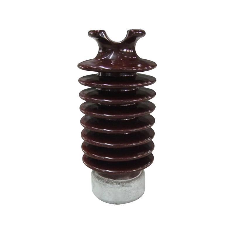
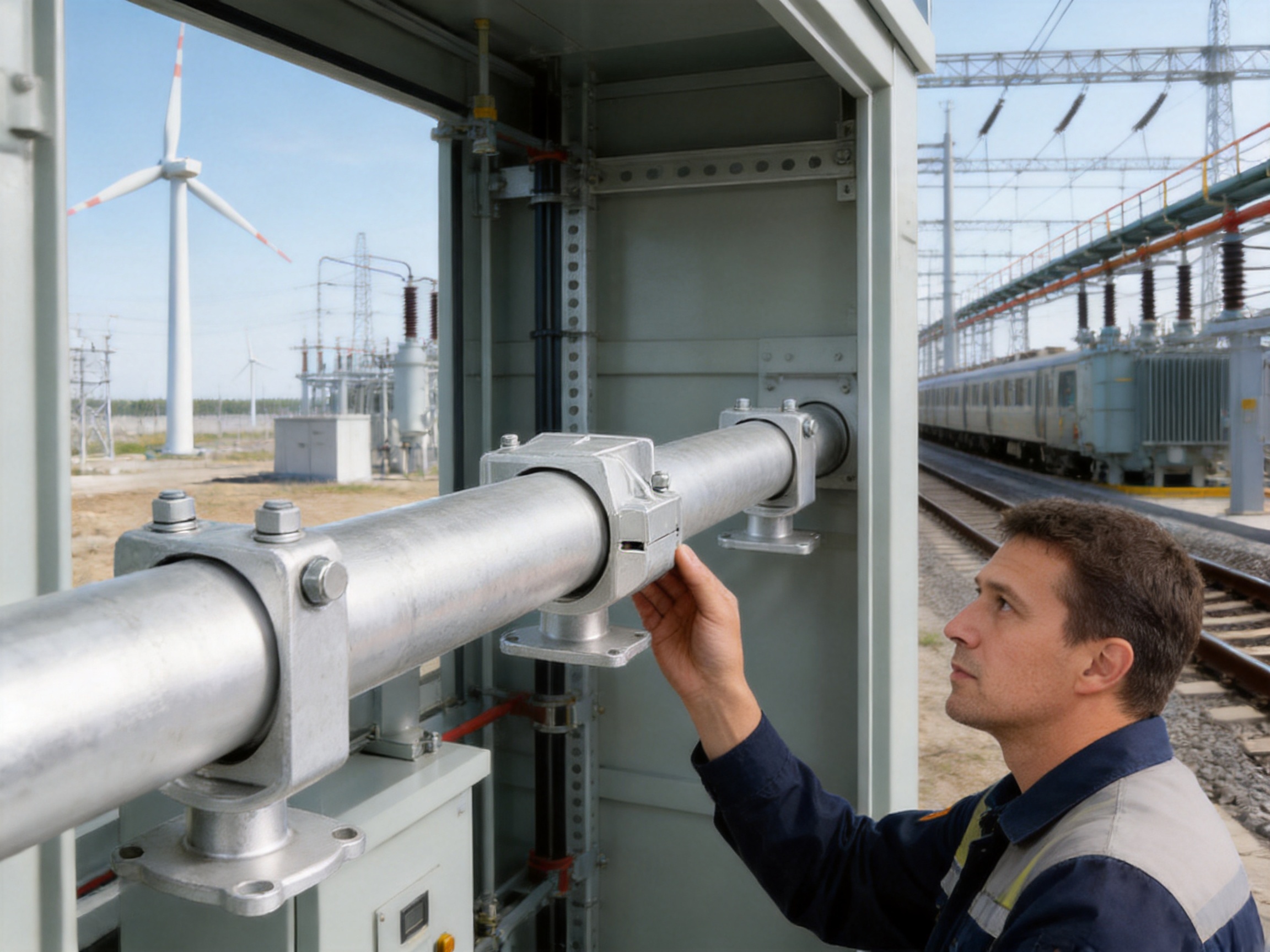
Bus-bar supports are essential mechanical and insulating components used to secure, align, and electrically separate busbars in power distribution and transmission equipment. Although they are compact compared with the busbars themselves, their performance directly influences system safety, reliability, service life, and maintenance requirements. A properly selected support system prevents unwanted movement, maintains designed clearances, withstands electrodynamic forces during short circuits, and helps preserve stable electrical insulation under demanding operating conditions.
For tubular busbar systems, support hardware must satisfy particularly demanding requirements. Tubular conductors may have considerable diameter, weight, and thermal expansion. They may also be installed in substations, industrial plants, wind power facilities, transformer stations, switchgear rooms, and other locations exposed to vibration, temperature changes, humidity, pollution, or corrosive atmospheres. The support assembly must therefore combine mechanical strength, dimensional accuracy, corrosion resistance, installation convenience, and compatibility with different conductor sizes.
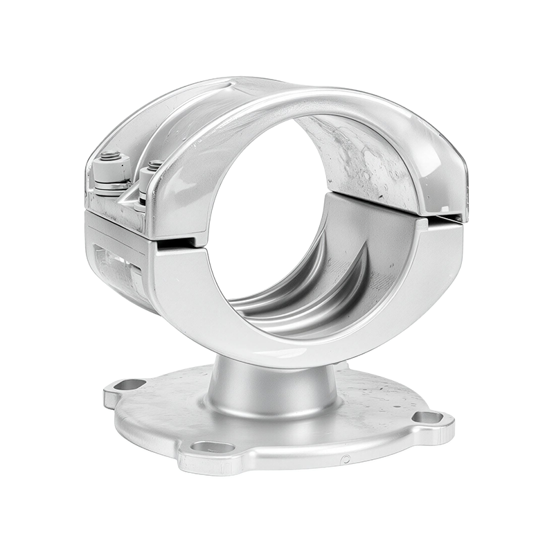
The fixed support type described in this article is designed for tubular busbar applications and forms part of a broader range of busbar hardware. The product family includes Type MGG fixed hardware, Type MGF end caps, tension clamps for steel strands, and supporting components for steel-cored aluminum conductors. Together, these products support the construction of reliable medium- and low-voltage busbar systems and related overhead or substation conductors.
Jiangsu Wopeng Power Technology Co., Ltd. develops and manufactures high- and low-voltage busbar systems and related accessories. Its production capabilities include vacuum casting, CNC machining, automated assembly, standardized testing, and engineering customization. These capabilities allow the company to supply components that are adapted to conductor dimensions, installation conditions, electrical ratings, mechanical loads, and project-specific requirements.
Bus-bar Supports (Fixed Support Type)
1. The Role of Bus-Bar Supports in Electrical Systems
Bus-bar supports hold conductors in a predetermined position while maintaining the required electrical clearance between phases and between energized parts and grounded structures. In switchgear and distribution cabinets, they also help transfer mechanical loads to the enclosure or mounting frame. In tubular busbar installations, they support the conductor at defined intervals and prevent excessive deflection, displacement, or vibration.
The support performs several functions simultaneously. First, it provides mechanical fixation. The busbar must remain stable during normal operation, transportation, installation, thermal expansion, and short-circuit events. Second, it provides electrical insulation. The support must resist leakage currents and surface tracking under the expected voltage, humidity, pollution, and temperature conditions. Third, it maintains dimensional consistency. Correct phase spacing and conductor alignment are necessary for safe operation and predictable electrical performance.
During a short circuit, very high electromagnetic forces can act on parallel conductors. These forces may attempt to push conductors apart, pull them together, or move them laterally depending on the system arrangement and current direction. A support that is adequate for normal operating weight may fail under a short-circuit impulse if its material strength, fixing method, or spacing is insufficient. For this reason, bus-bar supports should be selected according to both continuous service requirements and prospective fault conditions.
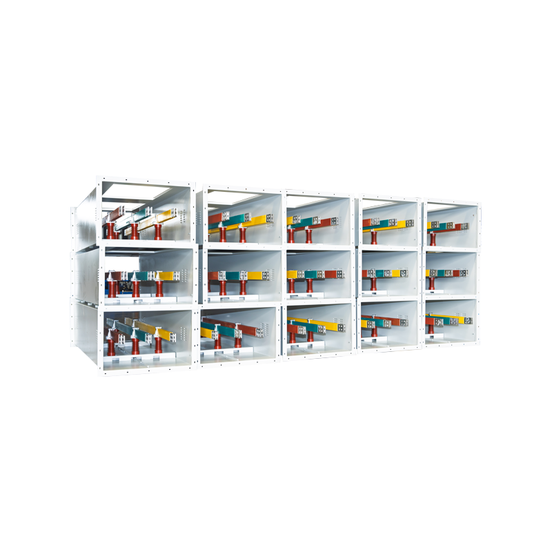
In medium-voltage and low-voltage distribution systems, supports are commonly installed in switchgear, distribution boxes, industrial control panels, transformer stations, renewable energy connection cabinets, and compact busbar assemblies. Larger tubular busbar systems may require fixed supports, sliding supports, expansion arrangements, damping accessories, and end sealing components to accommodate thermal movement while preserving structural stability.
Core Functions of a Fixed Support
A fixed support is intended to constrain the busbar at a specific location. It prevents uncontrolled movement and contributes to the overall stiffness of the busbar assembly. Depending on the system design, other support locations may allow controlled thermal movement, but fixed points are needed to establish a stable reference position.
The main functions include:
Mechanical fixation of the tubular conductor to the supporting structure.
Maintenance of phase-to-phase and phase-to-ground clearances.
Reduction of vibration and movement caused by electromagnetic forces, wind, transportation, or rotating equipment.
Transfer of conductor weight and short-circuit forces to the mounting structure.
Protection of the conductor surface from unsuitable direct contact with metal structures.
Support of consistent busbar geometry throughout the service life of the installation.
When appropriately engineered, a fixed support system can withstand short-circuit forces up to approximately 3,000 N in applicable designs and maintain high insulation resistance. The actual rating depends on the support configuration, material, conductor size, mounting method, spacing, and project conditions. Engineering verification should therefore be completed before final selection.
2. Product Scope and Configuration
The busbar support range is developed primarily for aluminum alloy tubular busbars and related power distribution applications. The products are designed to cover different conductor diameters and installation arrangements, allowing engineers to select suitable hardware without redesigning the complete busbar system.
Type MGG Fixed Hardware
Type MGG fixed hardware is used to secure tubular busbars at designated support points. The standard range is compatible with tubular busbar outer diameters from approximately 50 mm to 180 mm. This broad dimensional range makes the product suitable for many medium-current and high-current tubular busbar configurations.
Type MGG hardware is manufactured from hot-dip galvanized steel components. The galvanized surface protects the steel from atmospheric corrosion and improves service performance in industrial, outdoor, and humid environments. Standard and reinforced versions are available. The reinforced version is intended for installations where higher mechanical loads, larger conductors, stronger fault forces, or more demanding vibration conditions must be considered.
Dimensional parameters and weight data are defined for the different configurations. This helps engineers evaluate support spacing, mounting loads, transport requirements, and structural compatibility during the design stage. The fixed hardware can be integrated into customized support arrangements based on busbar diameter, installation orientation, support distance, and connection structure.
Type MGF End Caps
Type MGF end caps are used to seal the ends of tubular busbars. End sealing protects the interior of the tube from moisture, dust, foreign materials, and accidental contact. It also improves the neatness and safety of the finished installation.
The end caps are available in standard, damping, and terminal-ball types. They are compatible with tubular busbar inner and outer diameters ranging from approximately 50/45 mm to 250/230 mm, depending on the selected configuration. This range supports both relatively compact and large-diameter tubular conductors.
Damping types are equipped with LGJ-series damping wires. These components help improve vibration resistance and reduce the effects of mechanical oscillation. They are particularly useful in applications where the busbar may experience wind-induced vibration, equipment vibration, or repeated mechanical excitation. Available damping wire configurations include LGJ-240 through LGJ-630 designs, subject to the project specification.
Tension Clamps for Steel Strands
The product range also includes tension clamps for steel strands. These clamps are available in integral forged and universal design types. They are used to secure and maintain the required tension of steel strands in relevant conductor and support arrangements.
The clamps are compatible with steel strand diameters from approximately 7.8 mm to 16.0 mm. Grip strength ranges from approximately 45 kN to 187 kN, depending on the model. Hot-dip galvanized steel components provide mechanical durability and corrosion protection.
Integral forged designs offer high structural continuity and strength. Universal designs provide greater installation flexibility when a range of conductor or strand configurations must be accommodated. Selection should consider strand diameter, rated tensile load, installation method, environmental conditions, and the required safety factor.
Supporting Steel-Cored Aluminum Strands
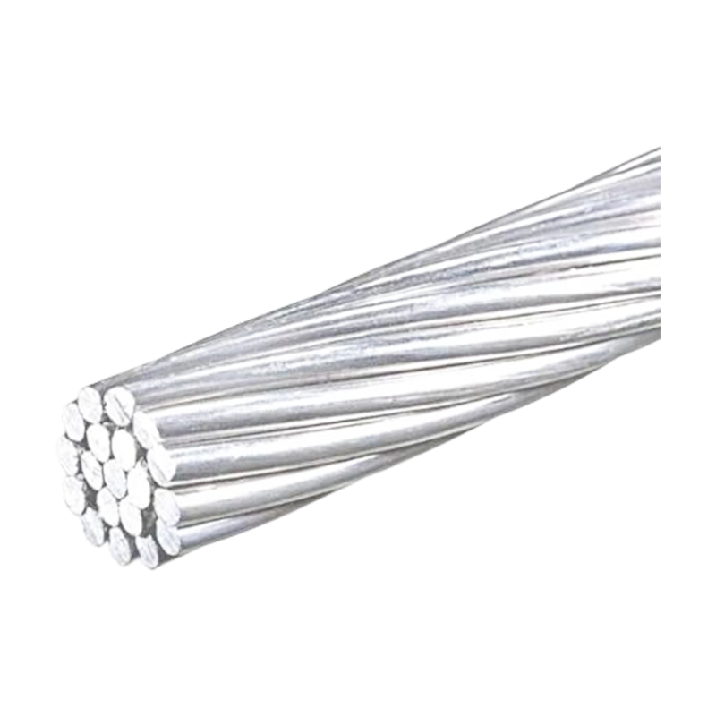
Supporting components for steel-cored aluminum conductors are designed in accordance with the relevant GB1179-83 requirements. Nominal cross-sections range from approximately 10/2 mm² to 240/30 mm². Standardized technical data may include calculated cross-sectional area, outside diameter, direct-current resistance, calculated tensile strength, and calculated weight.
These parameters help engineers match the conductor with suitable clamps, supports, terminal hardware, and tower or substation structures. Proper matching is important because conductor weight, tensile force, diameter, and electrical resistance all influence the mechanical and electrical design of the complete installation.
3. Materials and Surface Protection
Material selection is one of the most important factors in support performance. Tubular busbar supports must remain mechanically stable while exposed to electrical fields, temperature fluctuations, moisture, salt, industrial pollutants, and possible vibration. The selected material and surface treatment must therefore be appropriate for the complete operating environment.
Hot-Dip Galvanized Steel Components
Type MGG hardware, end caps, and tension clamp components use hot-dip galvanized steel where high mechanical strength and corrosion resistance are required. In the hot-dip galvanizing process, fabricated steel components are immersed in molten zinc. The resulting coating forms a protective barrier and provides sacrificial protection to exposed steel surfaces.
The specified zinc coating thickness is at least approximately 85 micrometers for the relevant hardware. A properly controlled coating improves resistance to atmospheric corrosion, moisture, and many industrial environments. It also reduces maintenance requirements compared with unprotected carbon steel.
Hot-dip galvanized steel provides a practical balance between strength, cost, availability, and environmental durability. Compared with some lightweight alternatives, steel hardware offers higher resistance to deformation under heavy loads and short-circuit forces. Compared with untreated steel, galvanized steel provides significantly better protection against rust and surface deterioration.
Insulating Composite Materials
Insulating support bodies in busbar systems may use DMC or SMC composite materials, depending on the application and design. DMC, or dough molding compound, and SMC, or sheet molding compound, are thermoset composite materials that can combine electrical insulation, mechanical strength, flame resistance, dimensional stability, and corrosion resistance.
DMC materials are commonly selected where reliable insulation and compact molded components are required. SMC materials can provide very high mechanical strength and may be advantageous for larger or more heavily loaded support systems. The final material selection depends on voltage level, short-circuit force, temperature, creepage requirements, flame-retardancy requirements, and the geometry of the support.
| Material | Typical Insulation Performance | Mechanical Strength | Indicative Temperature Resistance | Common Advantages |
|---|---|---|---|---|
| DMC | Excellent | High | -40°C to 180°C | Compact molding, good electrical insulation, flame resistance, and corrosion resistance |
| SMC | Excellent | Very high | -50°C to 200°C | High structural strength, dimensional stability, and suitability for reinforced support designs |
| Metal with protective coating | Requires insulating interface or separate insulator | Very high | Dependent on coating and surrounding materials | High load capacity and strong resistance to mechanical impact |
The use of composite insulating materials can provide advantages over ordinary plastics or unreinforced polymer components. Composite formulations can offer improved resistance to cracking, deformation, tracking, and flame propagation. Their performance is particularly valuable in compact switchgear where clearances are limited and support failure could create a serious electrical fault.
Low-Temperature Toughness
Electrical infrastructure may be installed in regions where temperatures fall significantly below freezing. Materials that become brittle at low temperatures can crack during installation or fail when subjected to impact and vibration. The described hardware is designed to maintain good toughness at temperatures down to approximately -40°C, provided that the selected configuration and material specification are suitable for the application.
Low-temperature performance is important for outdoor substations, wind farms, northern industrial facilities, and transportation infrastructure. It also supports reliable operation during rapid temperature changes, when differential expansion and contraction can place additional stress on the support assembly.
Corrosion Resistance
Corrosion can reduce cross-sectional area, weaken fasteners, increase contact resistance, and interfere with mechanical movement. The combination of hot-dip galvanizing, surface treatment, sandblasting, passivation, and optional enhanced coatings improves resistance to long-term environmental exposure.
The hardware is designed for demanding conditions, including C4-level corrosive environments when the appropriate protective solution is selected. Salt spray testing of up to approximately 3,000 hours and ultraviolet aging tests of up to approximately 2,000 hours are among the available validation approaches. Actual performance depends on the installation environment, coating system, cleaning practices, and exposure to chemicals or marine contaminants.
4. Mechanical Performance and Structural Reliability
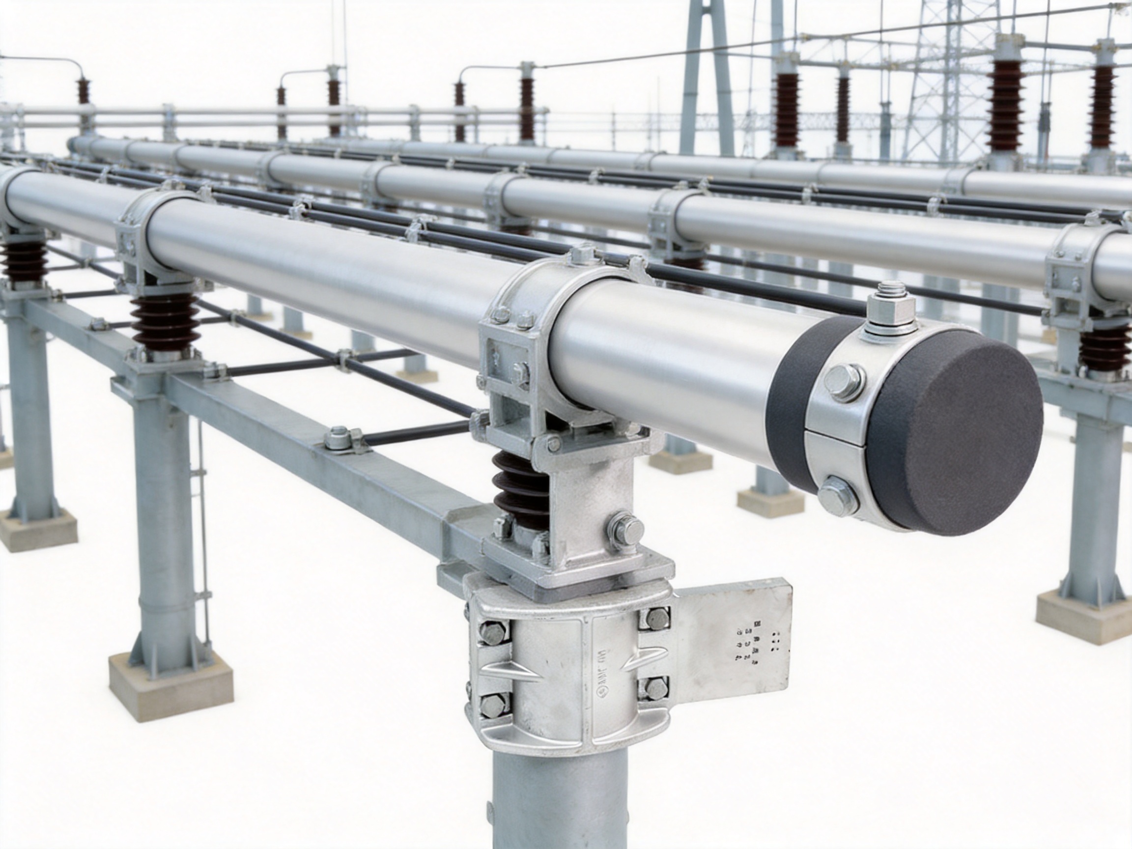
The mechanical performance of bus-bar supports is determined by material strength, geometry, fastener quality, fixing method, support spacing, conductor weight, and the expected fault current. A technically sound product must address all of these factors rather than relying only on nominal load capacity.
Short-Circuit Force Resistance
Short-circuit currents generate intense electromagnetic forces that can act within milliseconds. These forces may be considerably higher than the static weight of the busbar. The support must resist sudden loading without cracking, permanent deformation, bolt pull-out, or loss of phase clearance.
Reinforced fixed hardware is advantageous in high-current systems where larger tubular conductors or higher prospective fault currents are present. Reinforcement can improve load distribution and reduce local stress concentrations. Support geometry should be evaluated together with the mounting plate, bolts, brackets, and building structure because the weakest component determines the overall system capacity.
Finite Element Design Optimization
Finite element analysis can be used to identify high-stress areas and optimize the geometry of the support. By simulating static loads, short-circuit forces, vibration, and local contact pressure, engineers can improve material distribution and reduce unnecessary weight.
Stress optimization has several benefits. It may reduce the risk of fatigue cracking, improve dimensional stability, and allow the support to carry higher loads without excessive material use. It also helps verify that stress concentrations around bolt holes, corners, transitions, and conductor contact areas remain within acceptable limits.
Fatigue and Vibration Resistance
Busbar supports may experience repeated vibration caused by switching operations, transformers, rotating equipment, wind, transportation, or electromagnetic forces. Even when each individual load is below the static strength limit, repeated cycles can cause fatigue damage over time.
The described hardware is designed with fatigue life testing up to approximately 10 million vibration cycles. Resonance frequencies can be controlled outside the main operating range of the system to reduce the likelihood of amplified vibration. Damping end-cap configurations provide an additional option for installations where vibration resistance is a major design concern.
Vibration resistance is especially important in wind power facilities, railway systems, industrial plants, and outdoor substations. In these applications, the support should be assessed not only for conductor weight but also for the frequency, amplitude, and direction of repeated vibration.
Safety Factor and Load Distribution
The stated mechanical design uses a safety factor of approximately 2.5 for relevant hardware configurations. A safety factor provides a margin between the expected working load and the calculated or tested failure load. The correct margin depends on national standards, project specifications, fault levels, installation conditions, and the consequences of failure.
A well-designed support distributes pressure evenly around the tubular conductor and transfers force smoothly to the supporting structure. Uneven pressure can create local deformation, surface damage, or stress concentration. Correct tightening torque and compatible contact materials are equally important during installation.
5. Electrical Performance and Insulation Safety
Although bus-bar supports are primarily mechanical components, their electrical performance is equally important. Supports are located close to energized conductors and must maintain insulation under normal operation, overload, short-circuit, humidity, pollution, and temperature cycling.
Insulation Resistance
High insulation resistance reduces leakage current and helps prevent unintended current paths between phases or from the conductor to ground. The described support systems are designed to maintain insulation resistance above 1.0 × 10¹² ohms in applicable configurations. Under humid and hot conditions, insulation resistance can remain above approximately 10⁴ megohms when the correct materials and construction are used.
Actual insulation performance depends on creepage distance, clearance, surface cleanliness, moisture, contamination, material formulation, molding quality, and installation torque. It is therefore important to keep insulating surfaces clean and to prevent the accumulation of conductive dust, oil, salt, or chemical deposits.
Electrothermal Coupling
High-current busbars generate heat, and the support design must account for the interaction between current, temperature, electromagnetic fields, and mechanical structure. Poorly designed metallic parts may create undesirable circulating currents or localized heating. These effects can increase energy losses and accelerate material aging.
The hardware design considers electrothermal coupling and seeks to reduce eddy-current losses through appropriate structural configuration. Electromagnetic force calculations under short-circuit conditions are used to verify system stability. Contact resistance is controlled below approximately 50 micro-ohms in relevant conductive connections, helping reduce localized heating and energy loss.
Corona and Partial Discharge Control
At higher voltage levels, sharp edges, small radii, gaps, and uneven surfaces can intensify electric fields and create corona or partial discharge. These phenomena may produce noise, ozone, insulation deterioration, and long-term reliability problems.
An anti-corona design uses suitable contours, smooth surfaces, controlled clearances, and appropriate end hardware to reduce electric-field concentration. The Type MGF terminal-ball configuration can support smooth termination arrangements where field control is required. The exact design should be selected according to the system voltage, conductor geometry, insulation arrangement, and applicable electrical clearances.
6. Applications in Medium- and Low-Voltage Systems
Fixed bus-bar supports are used in many electrical distribution environments. Their compact design and broad dimensional compatibility make them suitable for both equipment-mounted and structure-mounted installations.
Switchgear and Distribution Cabinets
In low-voltage switchboards and medium-voltage switchgear, supports maintain the position of busbars and preserve phase separation. They must fit within limited enclosure space while allowing sufficient creepage and clearance distances. Reinforced versions may be used where high fault currents or heavy conductors create increased mechanical loads.
The support arrangement also affects inspection and maintenance. A well-designed system allows technicians to verify conductor alignment, bolt condition, insulation surfaces, and thermal clearances without removing unnecessary components.
Transformer Stations and Substations
Transformer stations and substations require busbar supports that can operate reliably outdoors or in partially enclosed environments. Exposure to ultraviolet radiation, rain, humidity, temperature variation, and pollution makes corrosion resistance particularly important.
Hot-dip galvanized steel hardware and weather-resistant insulating materials help extend service life. Support spacing and structural design should be coordinated with transformer connections, expansion arrangements, cable terminations, and grounding structures.
Industrial Power Distribution
Industrial plants may experience vibration, dust, chemical exposure, high ambient temperatures, and frequent switching. Bus-bar supports used in these facilities need to maintain mechanical stability and insulation over long operating periods.
In steel mills, manufacturing plants, chemical facilities, and large processing sites, the selection of corrosion protection and insulating material should reflect the actual atmosphere. Enhanced coatings may be appropriate in areas exposed to aggressive chemicals, salt, or persistent condensation.
Renewable Energy Installations
Wind power facilities and renewable energy grid connection cabinets often combine high current, vibration, outdoor exposure, and changing operating conditions. Tubular busbar supports used in these systems should be assessed for fatigue, thermal expansion, ultraviolet exposure, and wind-induced movement.
Damping end caps and reinforced fixed supports may be selected when vibration or mechanical loading is significant. The complete design should consider nacelle movement, tower vibration, transformer connections, and the dynamic behavior of the conductor assembly.
Rail Transit and Large Commercial Facilities
Rail transit systems and large commercial buildings require compact, reliable power distribution equipment with strong safety characteristics. Busbar supports can be used in feeder systems, distribution cabinets, traction-related equipment, and high-capacity electrical rooms.
Flame-retardant insulating materials, stable dimensions, and low maintenance requirements are beneficial in occupied facilities. Where applicable, DMC or SMC materials may meet UL94 V-0 flame-retardancy requirements, subject to the exact material grade and product certification.
7. Advantages Over Conventional and Competing Solutions
The performance advantages of a bus-bar support should be evaluated against conventional unprotected steel brackets, ordinary plastic supports, poorly matched universal clamps, and products with limited environmental or mechanical verification.
Broader Dimensional Compatibility
Type MGG fixed hardware supports tubular busbar outer diameters from approximately 50 mm to 180 mm. Type MGF end caps cover inner and outer diameter combinations from approximately 50/45 mm to 250/230 mm. This range reduces the need for multiple unrelated suppliers and allows a project to standardize hardware across different conductor sizes.
Broad compatibility is also useful for replacement and retrofit projects. Engineers can often select a suitable model for an existing tubular busbar without modifying the entire support structure. Final dimensional confirmation remains necessary because manufacturing tolerances, wall thickness, fixing holes, and end geometry may vary.
Higher Mechanical Security
Compared with lightweight, non-reinforced supports, reinforced hardware provides greater resistance to high short-circuit forces and heavy conductor loads. Forged tension clamp designs offer improved structural continuity compared with assemblies made from several loosely connected parts.
Finite element analysis, fatigue testing, and controlled resonance behavior provide additional evidence of structural reliability. These features are valuable in systems where failure could interrupt power supply, damage adjacent equipment, or create a safety hazard.
Improved Corrosion Protection
Hot-dip galvanizing with a controlled coating thickness offers a more durable solution than ordinary electroplated or painted steel in many outdoor and industrial applications. Additional sandblasting, passivation, and enhanced coating options improve the ability of the hardware to operate in severe environments.
Corrosion protection also helps preserve contact geometry and fastening reliability. A support that maintains its dimensions and bolt integrity over time is more likely to preserve the original phase spacing and mechanical performance of the busbar system.
Integrated Product Family
A complete range of fixed hardware, end caps, damping accessories, tension clamps, and conductor support components simplifies system engineering. Instead of treating every component as an isolated purchase, engineers can coordinate the mechanical and electrical functions of the complete assembly.
Integrated supply can reduce interface problems between different manufacturers. It can also simplify documentation, spare-parts management, inspection, and technical communication during installation and commissioning.
Customization Capability
Projects often require non-standard conductor diameters, mounting arrangements, support spacing, environmental protection, or reinforced structures. A manufacturer with engineering and production capabilities can adapt the support to project-specific conditions.
Customization may include dimensional modification, special bolt patterns, reinforced brackets, alternative surface coatings, damping configurations, material adjustments, or matching accessories. OEM supply is particularly useful for switchgear manufacturers, busbar system integrators, EPC contractors, and power equipment distributors.
8. Advanced Manufacturing Processes
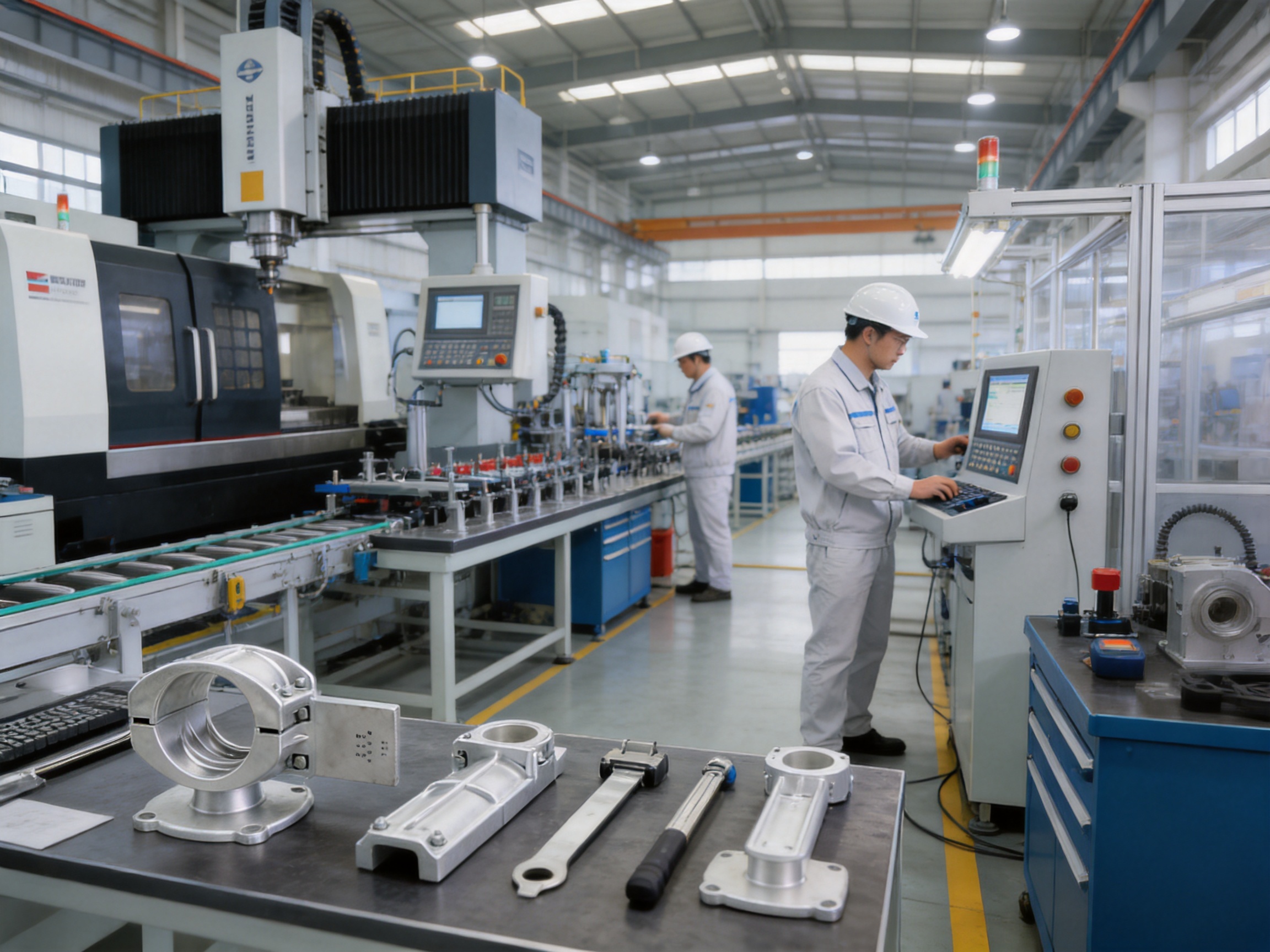
The reliability of bus-bar supports depends not only on the design but also on manufacturing consistency. Jiangsu Wopeng Power Technology operates production lines equipped with vacuum casting systems, CNC machining equipment, and automated assembly technologies. These processes support repeatable dimensions, controlled material quality, and efficient production of customized components.
Vacuum Casting
Vacuum casting is used in the manufacture of epoxy resin and other cast insulating components. By reducing trapped air and improving material flow, vacuum casting can reduce voids, bubbles, and internal defects that may weaken insulation or mechanical strength.
For cast-resin busbar products and insulating support components, process control is essential. Resin mixing ratio, vacuum level, mold temperature, curing time, and post-curing conditions must be monitored. Consistent curing improves dielectric strength, dimensional stability, thermal performance, and resistance to cracking.
Vacuum-cast insulation is especially valuable in medium-voltage applications where partial discharge performance and long-term dielectric reliability are important. It can also provide a compact and well-sealed structure that is less vulnerable to moisture penetration than poorly processed porous materials.
CNC Machining
CNC machining provides accurate control of holes, slots, mounting faces, grooves, and contact surfaces. Dimensional accuracy is important because the support must align with the tubular conductor and the mounting structure. Small deviations can influence phase spacing, contact pressure, installation time, and load distribution.
CNC equipment is also useful for producing customized hardware in relatively small batches. Instead of relying only on fixed tooling, manufacturers can modify digital machining programs for different conductor diameters or mounting requirements. This flexibility supports OEM projects and special engineering applications.
Die Forging and Heat Treatment
Die forging can improve the strength and structural integrity of steel clamp components. The forging process forms the metal under controlled pressure, helping produce a dense grain structure and reducing the risk of internal discontinuities associated with unsuitable casting or low-quality fabrication.
Heat treatment is used to achieve the required balance between hardness, tensile strength, toughness, and fatigue resistance. A component that is excessively hard may become brittle, while one that is too soft may deform under load. Controlled heat treatment helps ensure reliable mechanical performance across a wide temperature range.
Automated Assembly
Automated assembly technologies improve repeatability and reduce variation in the installation of washers, fasteners, insulating interfaces, and other components. Proper assembly is essential because the performance of a support can be reduced by incorrect orientation, insufficient tightening, excessive tightening, or missing hardware.
Automation can also support traceability. Production records may identify the material batch, process parameters, inspection results, and assembly status of each product group. Traceability helps manufacturers investigate field issues and improves quality management throughout the supply chain.
Surface Treatment
Surface sandblasting, passivation, and galvanizing are used to improve the durability of metal components. Surface preparation removes contaminants and improves coating adhesion. Passivation helps stabilize the surface after treatment, while galvanizing provides a protective zinc layer.
For installations in especially severe environments, enhanced anti-corrosion coating systems may be specified. The coating selection should account for salt exposure, ultraviolet radiation, industrial chemicals, humidity, temperature, and the possibility of mechanical damage during transport or installation.
9. Quality Control and Testing
Quality control should cover raw materials, machining, forming, coating, assembly, electrical insulation, and final dimensions. A manufacturer serving power distribution projects must maintain a documented inspection system because support failure may affect the safety of the entire electrical installation.
Material Inspection
Steel, zinc, composite resin, reinforcing fibers, fasteners, and other materials should be checked against the specified grades and technical requirements. Material certificates, chemical composition records, mechanical test results, and coating inspection reports may be maintained as part of the quality documentation.
Dimensional Inspection
Dimensional inspection verifies conductor diameter compatibility, mounting hole position, contact radius, support width, overall height, and clearance-related dimensions. Accurate measurement is especially important for fixed hardware and end caps because an incorrect fit can create movement or excessive contact pressure.
Mechanical Verification
Mechanical tests may include tensile testing, grip-strength testing, static load testing, bolt torque verification, impact evaluation, and vibration or fatigue testing. For tension clamps, grip strength should be checked against the specified range, which may extend from approximately 45 kN to 187 kN depending on the model.
Short-circuit force calculations and structural simulations should be supplemented by practical testing where required by the project or applicable standard. The test configuration should represent the actual conductor, support spacing, mounting structure, and loading direction as closely as possible.
Electrical Testing
Electrical tests may include insulation resistance, dielectric withstand, partial discharge, contact resistance, temperature-rise, and continuity tests. The selection of tests depends on whether the component is insulating, conductive, or part of a complete busbar assembly.
Contact resistance below approximately 50 micro-ohms is targeted for relevant conductive connections. Low resistance reduces I²R heating and improves the stability of high-current connections. Insulation resistance and withstand testing help verify that the support and its insulating interfaces will not create unwanted leakage paths.
Environmental Testing
Environmental validation may include salt spray exposure, ultraviolet aging, temperature cycling, humidity testing, and low-temperature evaluation. The reported validation capabilities include up to approximately 3,000 hours of salt spray testing and 2,000 hours of ultraviolet aging testing.
Environmental testing does not eliminate the need for correct installation and maintenance. Drainage, ventilation, cleaning, coating inspection, and protection from incompatible chemicals remain important throughout the product life cycle.
10. Engineering Selection Guide
Selecting the correct bus-bar support requires more than matching the conductor diameter. Engineers should evaluate the electrical system, mechanical loads, environment, installation method, and maintenance requirements as a complete design.
Step One: Confirm the Conductor Dimensions
Measure or confirm the tubular busbar outside diameter, inside diameter, wall thickness, length, material, and connection geometry. For end caps, both inner and outer diameters are important. Tolerance information should also be reviewed to ensure that the selected component provides a secure fit without damaging the conductor.
Step Two: Determine the Electrical Rating
Confirm the system voltage, continuous current, short-circuit current, frequency, insulation level, phase spacing, and required creepage distance. Systems from approximately 0.4 kV to 35 kV may use different insulation arrangements and field-control requirements. The support should be selected as part of the complete insulation coordination design.
Step Three: Calculate Mechanical Loads
Consider the conductor weight, support span, wind load, seismic force, thermal expansion, transportation loads, and short-circuit electromagnetic forces. Select standard or reinforced fixed hardware according to the calculated loads rather than relying only on nominal conductor size.
Step Four: Evaluate the Environment
Review ambient temperature, humidity, ultraviolet exposure, salt, industrial pollutants, chemical vapors, dust, altitude, and indoor or outdoor installation. A standard galvanized product may be sufficient for one site, while an enhanced coating system may be necessary for a coastal or chemically aggressive location.
Step Five: Coordinate Fixed and Moving Points
A tubular busbar system may require a combination of fixed supports and supports that permit controlled thermal movement. The location of fixed points influences expansion, connection loads, and conductor stress. End caps, damping accessories, and flexible connections should be coordinated with the support layout.
Step Six: Confirm Installation Details
Check bolt sizes, mounting plate thickness, hole patterns, tightening torque, access space, grounding arrangements, and tools required for installation. The support should be accessible for inspection and should not interfere with cable terminations, switches, sensors, or other equipment.
11. Installation and Maintenance Recommendations
Correct installation is necessary to obtain the designed performance of the support system. Before installation, inspect the conductor, support, fasteners, coating, and insulating surfaces. Do not use components with cracks, severe scratches, deformation, contaminated insulation, damaged threads, or incomplete coatings.
Confirm that the support is aligned with the conductor centerline and that the mounting structure is rigid. Misalignment can introduce bending stress and uneven contact pressure. The tubular busbar should be positioned without forcing it into the support or using excessive mechanical impact.
Fasteners should be tightened according to the specified torque. Under-tightening may permit movement and vibration, while over-tightening may damage composite parts or deform the conductor. Where electrical connections are involved, clean contact surfaces and approved joint compounds should be used in accordance with the project specification.
After installation, verify phase spacing, grounding clearance, conductor alignment, bolt condition, and the absence of sharp edges or unintended conductive paths. For medium-voltage systems, perform the required insulation, withstand, partial-discharge, and routine commissioning tests.
During service, inspections should focus on corrosion, coating damage, loosened fasteners, cracking, discoloration, vibration marks, contamination, and changes in conductor alignment. Thermal imaging may help identify high-resistance conductive joints or abnormal heating. In high-vibration locations, inspection intervals should be adjusted according to operating experience.
12. Manufacturing and OEM Support Strengths
Jiangsu Wopeng Power Technology was founded in 2018 as a specialized high- and low-voltage busbar technology enterprise. The company focuses on the development and manufacture of high-current power transmission products and related accessories.
Its product portfolio includes 35 kV epoxy resin vacuum-cast tube busbars, low-voltage cast-resin busways, copper and aluminum tubular busbars, wind power tubular busbars, compact busbar systems, sliding contact line systems, and associated hardware. This product breadth allows the company to understand the interaction between busbars, supports, insulation, connectors, and installation structures.
The company serves power generation, substations, wind energy, industrial manufacturing, rail transit, and large commercial facilities. Its products operate across more than 17 provinces and in multiple industrial sectors, providing practical experience in different climates, installation methods, and load conditions.
Engineering personnel, technical specialists, and production professionals support product development and project customization. The combination of design capability and manufacturing control is particularly important for bus-bar supports because many projects require dimensional adaptation, reinforced structures, special coatings, or coordinated hardware packages.
Modern manufacturing equipment includes vacuum casting systems, CNC machining equipment, and automated assembly lines. Standardized inspection procedures include high-voltage tests, insulation tests, mechanical verification, dimensional checks, and routine quality inspections. Collaboration with third-party testing institutions provides additional independent validation of safety and performance.
These capabilities create several advantages for OEM customers and system integrators. They can obtain technical assistance during product selection, coordinate support hardware with the busbar design, request customized dimensions, and receive documentation for installation and quality approval. A single technical interface can also reduce coordination delays during project execution.
13. Sustainability, Service Life, and Total Cost
The total value of a bus-bar support is determined not only by its purchase price but also by installation time, maintenance frequency, service life, failure risk, and replacement difficulty. Corrosion-resistant hardware and durable insulating materials can reduce the need for repeated replacement in difficult environments.
Accurate dimensions reduce installation adjustments and minimize the risk of rework. An integrated product family reduces the possibility of incompatibility between supports, clamps, and end caps. Reliable mechanical performance helps protect expensive conductors and adjacent switchgear from damage during fault events.
Long service life also contributes to sustainability. Components that maintain their mechanical and electrical properties for many years reduce material consumption, transportation, shutdowns, and maintenance activities. Properly selected galvanized steel and composite materials can provide a practical balance between durability and resource efficiency.
For a complete project evaluation, buyers should compare technical specifications, test documentation, coating requirements, delivery capability, customization support, spare-parts availability, and after-sales service in addition to unit price.
14. Frequently Asked Questions
Q1: What are bus-bar supports used for?
Bus-bar supports secure and align busbars while maintaining electrical clearance and insulation. They also transfer conductor weight and short-circuit forces to the supporting structure and help control vibration and movement.
Q2: What is the difference between fixed hardware and a sliding support?
Fixed hardware constrains the busbar at a designated reference point. A sliding support allows controlled movement, usually to accommodate thermal expansion. A complete tubular busbar installation may require both types, depending on conductor length and temperature variation.
Q3: What tubular busbar diameters are compatible with Type MGG fixed hardware?
Type MGG fixed hardware is designed for tubular busbar outer diameters from approximately 50 mm to 180 mm. The exact model should be selected according to the conductor tolerance, support configuration, loading, and mounting arrangement.
Q4: What are Type MGF end caps used for?
Type MGF end caps seal the ends of tubular busbars and help prevent moisture, dust, foreign objects, and accidental contact from entering the conductor. Standard, damping, and terminal-ball configurations are available.
Q5: When should reinforced busbar supports be selected?
Reinforced supports are appropriate when the system involves large or heavy conductors, high prospective short-circuit current, long support spans, strong vibration, seismic loading, outdoor exposure, or other conditions that increase mechanical stress.
Q6: Are the supports suitable for medium-voltage systems?
Yes. The product range is intended for medium- and low-voltage applications, with system examples extending from approximately 0.4 kV to 35 kV. Voltage level alone is not sufficient for selection; insulation coordination, clearance, creepage, current, fault level, and environmental conditions must also be reviewed.
Q7: What materials are used for the supports?
Metal hardware is manufactured from hot-dip galvanized steel in relevant designs. Insulating bodies may use DMC or SMC composite materials. The selected material depends on mechanical loading, electrical insulation, temperature, flame-retardancy, and environmental requirements.
Q8: How does hot-dip galvanizing improve performance?
Hot-dip galvanizing creates a protective zinc coating that shields steel from atmospheric corrosion and provides sacrificial protection if the surface is locally damaged. The specified coating thickness for relevant hardware is at least approximately 85 micrometers.
Q9: Are the supports flame retardant?
Applicable DMC and SMC insulating materials may meet UL94 V-0 flame-retardancy requirements, depending on the exact grade and certification. Customers should request the relevant material and test documentation for the selected product.
Q10: Can the support hardware be customized?
Yes. Customization may include conductor dimensions, mounting holes, bracket geometry, reinforcement, coating, damping configuration, and coordinated accessories. Technical drawings and operating conditions should be provided before production.
Q11: What information should be supplied when requesting a quotation?
Useful information includes busbar material, inner and outer diameter, wall thickness, system voltage, rated current, short-circuit current, support spacing, installation orientation, indoor or outdoor location, ambient temperature, corrosion category, required standards, quantity, and delivery schedule.
Q12: How are the products tested?
Testing may include dimensional inspection, material verification, mechanical testing, grip-strength testing, insulation resistance, dielectric withstand, contact resistance, temperature-rise evaluation, vibration testing, salt spray exposure, ultraviolet aging, and routine quality checks. The specific tests depend on the product and project requirements.
Q13: Can the products be used in wind power installations?
Yes. Tubular busbar supports and damping accessories can be applied in wind power systems when the design accounts for vibration, temperature changes, wind-induced movement, current, insulation, and mechanical fatigue. A project-specific mechanical assessment is recommended.
Q14: How should bus-bar supports be maintained?
Maintenance should include visual inspection of corrosion, cracks, coating damage, loose fasteners, contamination, vibration marks, and conductor alignment. Periodic electrical and thermal inspections may also be required for the complete busbar system.
Conclusion
Bus-bar supports are fundamental to the safety and reliability of tubular busbar systems. Their responsibilities extend beyond simply holding a conductor in place. They must maintain electrical insulation, preserve phase spacing, withstand short-circuit forces, resist vibration, manage environmental exposure, and remain dimensionally stable throughout the operating life of the installation.
The described product range combines Type MGG fixed hardware, Type MGF end caps, damping options, tension clamps, and support components for steel-cored aluminum conductors. Broad diameter compatibility, standard and reinforced configurations, hot-dip galvanized steel, DMC and SMC insulating materials, corrosion protection, mechanical analysis, fatigue testing, and electrical performance verification provide a strong foundation for demanding power applications.
Jiangsu Wopeng Power Technology supports these products with vacuum casting, CNC machining, die forging, heat treatment, automated assembly, standardized inspection, and OEM engineering services. Its experience across tubular busbars, cast-resin busways, compact busbar systems, wind power equipment, and sliding contact line systems enables coordinated solutions rather than isolated components.
For engineers, contractors, switchgear manufacturers, and distributors, the most suitable bus-bar support should be selected through a complete technical evaluation covering conductor geometry, electrical rating, fault current, support spacing, thermal movement, environment, installation method, and applicable standards. When these factors are properly coordinated, fixed bus-bar supports can deliver long-term mechanical stability, dependable insulation, reduced maintenance, and secure operation in medium- and low-voltage power distribution systems.
References
GB1179-83, Aluminum Stranded Conductors and Steel-Reinforced Aluminum Conductors.
UL 94, Standard for Tests for Flammability of Plastic Materials for Parts in Devices and Appliances.
IEC 61439, Low-Voltage Switchgear and Controlgear Assemblies.
IEC 62271, High-Voltage Switchgear and Controlgear.
IEC 60071, Insulation Co-ordination.
ASTM B117, Standard Practice for Operating Salt Spray Apparatus.
Relevant technical specifications for tubular busbar support hardware, galvanized steel components, composite insulating materials, and conductor clamps.
Manufacturer technical documentation for Type MGG fixed hardware, Type MGF end caps, tension clamps, and supporting steel-cored aluminum conductor products.
Product: Bus-bar Supports (Fixed Support Type)




-
 +86-180 3625 3000
-
 admin@wpbusbar.com
-
 No. 8, Yanjin Road, Chengxi Industrial Park, Shanyang Town, Baoying County, Yangzhou City, Jiangsu Province, China
Copyright © Jiangsu Wopeng Power Technology Co., Ltd.
All Rights Reserved.
 Custom Insulated Bus Bar Manufacturer
Tubular Busbar System Factory
Custom Insulated Bus Bar Manufacturer
Tubular Busbar System Factory