

 EN
EN

 English
 русский
 Français
 Español
 عربى
عربى


High-Density Compact Busway: Engineering, Performance, Applications, and Manufacturing Advantages
Content
- 1 1. Understanding High-Density Compact Busway Technology
- 2 2. Product Positioning in Low-Voltage Distribution Systems
- 3 3. Core Technical Specifications
- 4 4. Dense Structural Design and Space Efficiency
- 5 5. Epoxy Resin Vacuum Casting Technology
- 6 6. Copper Conductors and Electrical Performance
- 7 7. Aluminum Alloy Enclosure and Mechanical Protection
- 8 8. Safety and Reliability Advantages
- 9 9. Plug-In Distribution and Modular Expansion
- 10 10. Comparison with Traditional Cable Systems
- 11 11. Advantages over Conventional Air-Insulated Bus Duct
- 12 12. Application in Data Centers
- 13 13. Application in Industrial Manufacturing
- 14 14. Application in Commercial Buildings and Infrastructure
- 15 15. Manufacturing Strengths and Process Control
- 16 16. Testing and Quality Assurance
- 17 17. Engineering and OEM Support
- 18 18. Installation Considerations
- 19 19. Operating Life and Maintenance
- 20 20. Energy Efficiency and Life-Cycle Value
- 21 21. Environmental and Application Limitations
- 22 22. Why Select an Experienced Busbar Manufacturer
- 23 23. Frequently Asked Questions
- 23.1 Q1: What is a high-density compact busway?
- 23.2 Q2: What voltage level is this product designed for?
- 23.3 Q3: What current range is available?
- 23.4 Q4: Why is epoxy resin casting used?
- 23.5 Q5: What conductor material is used?
- 23.6 Q6: Can the compact busway replace traditional cable systems?
- 23.7 Q7: Is the busway suitable for data centers?
- 23.8 Q8: Can the system be expanded after installation?
- 23.9 Q9: What protection rating does the product provide?
- 23.10 Q10: What fire performance is specified?
- 23.11 Q11: How long can the busway operate?
- 23.12 Q12: What tests are performed before delivery?
- 23.13 Q13: Can customized OEM solutions be provided?
- 23.14 Q14: What should customers provide when requesting a quotation?
- 24 24. Conclusion
- 25 References
- 26 Product: High-density Compact Busway
Modern electrical distribution systems must deliver large quantities of power safely while occupying less space, reducing installation complexity, and supporting future expansion. High-density compact busway technology addresses these requirements by combining closely arranged conductors, advanced insulation, modular construction, and high mechanical protection in a single integrated power distribution system. Compared with traditional cable installations and larger air-insulated bus duct systems, compact busways offer a smaller footprint, faster installation, improved electrical organization, and strong adaptability for demanding facilities.
The high-density compact busway described in this article is designed for low-voltage power distribution systems operating at 0.4 kV. It uses copper conductors, epoxy resin casting technology, a high-strength aluminum alloy enclosure, flame-retardant phase barriers, and plug-in connection technology. The resulting system provides full insulation protection, efficient heat dissipation, dependable electrical performance, and long-term service capability.
With a rated current range from 400 A to 5000 A, rated voltage of AC 400 V/690 V, insulation class F, and protection up to IP65, this type of busway can serve industrial facilities, commercial buildings, data centers, infrastructure projects, substations, transportation facilities, and other high-current applications. Its compact structure is particularly valuable where electrical rooms, vertical shafts, service corridors, and equipment areas have limited space.
1. Understanding High-Density Compact Busway Technology
A busway, also known as busbar trunking, is a prefabricated electrical distribution system that transfers power through enclosed conductors rather than through multiple independent cables. It normally consists of conductive bars, insulation, an enclosure, joints, connection units, and tap-off devices. The system can be installed horizontally or vertically and can distribute power from a main switchboard to panels, machinery, server racks, production lines, or other loads.
High-density compact busway is a specialized design in which the conductors are arranged closely together. The dense arrangement reduces the overall cross-sectional size while preserving a high current-carrying capacity. The compact structure also improves mechanical strength and allows the system to fit into narrow electrical shafts, plant corridors, ceiling spaces, and equipment rooms.
Unlike conventional open or air-insulated bus duct systems, the conductors in a cast-resin compact busway are embedded in an epoxy resin insulation system. Integral vacuum casting helps create a dense, void-free insulation structure around the conductors. This construction protects the conductive components from dust, moisture, accidental contact, and many external mechanical influences.
The insulation system also separates the phases and provides a stable dielectric environment. Internal flame-retardant barriers help maintain safe phase-to-phase spacing, while the metal enclosure provides an additional layer of mechanical protection and electromagnetic containment. The combination of insulation and enclosure creates a highly integrated power distribution product rather than a collection of individually installed cables.
For low-voltage power distribution, the system is commonly connected to switchboards, transformers, distribution cabinets, motor control centers, power panels, or large equipment. Plug-in units can be positioned along the busway route to supply loads at selected points. This arrangement reduces the need to install separate long cable runs every time equipment is added or relocated.
2. Product Positioning in Low-Voltage Distribution Systems
The high-density compact busway serves as a critical connection and distribution device within low-voltage electrical networks. Its primary function is to transfer electrical energy from an upstream power source to multiple downstream loads in a safe, organized, and efficient manner.
In a typical 0.4 kV distribution system, power may flow from a transformer or main switchboard into the busway. The busway then carries the current along a defined route, with tap-off units or plug-in boxes supplying local panels, machinery, floors, production cells, or server cabinets. This architecture allows the electrical distribution route to be planned as a modular backbone.
The product is especially suitable for projects where the load arrangement may change during the operating life of the facility. Commercial buildings, data centers, manufacturing plants, and logistics centers often need to add equipment or change floor layouts. A modular busway can accommodate these changes more easily than a fixed cable installation.
Another important characteristic is its ability to support high-current distribution in a relatively narrow space. The rated current range of 400 A to 5000 A covers a broad selection of low-voltage applications. The design can therefore be adapted to feeder circuits, main distribution routes, production lines, large mechanical systems, and high-density equipment zones.
The rated voltage of AC 400 V/690 V enables the system to serve common low-voltage industrial and commercial networks. Its Class F insulation rating provides a substantial thermal margin for normal operation, while the IP65 protection rating helps shield the internal conductors from dust and water jets under suitable installation conditions.
3. Core Technical Specifications
The performance of a compact busway depends on the interaction between conductor material, insulation, enclosure, joint design, thermal management, and manufacturing quality. The principal specifications of this product are summarized below.
| Item | Specification | Engineering Significance |
|---|---|---|
| Product type | Low-voltage cast-resin compact busway | Provides a fully insulated and enclosed power distribution route |
| Rated current | 400 A to 5000 A | Supports feeder, distribution, industrial, and high-density equipment loads |
| Rated voltage | AC 400 V/690 V | Suitable for common low-voltage distribution systems |
| Insulation class | Class F | Provides a high thermal capability for electrical insulation |
| Protection rating | Up to IP65 | Improves resistance to dust and water ingress |
| Conductor | High-purity copper with tin plating | Combines high conductivity with improved surface protection |
| Short-time withstand current | 50 kA for 1 second | Supports demanding short-circuit conditions |
| Power-frequency withstand voltage | 3500 V for 1 minute | Verifies dielectric strength under test conditions |
| Temperature rise | Below 70 K | Helps control thermal stress during normal operation |
| Fire performance | UL94 V-0 | Supports flame-retardant performance of relevant materials |
| Seismic capability | Up to intensity level 8 | Supports use in areas requiring enhanced mechanical stability |
These specifications should always be reviewed together with the project design, installation environment, ambient temperature, current demand, fault level, route length, joint configuration, and applicable standards. Correct system selection is essential to ensure that the busway operates within its design limits.
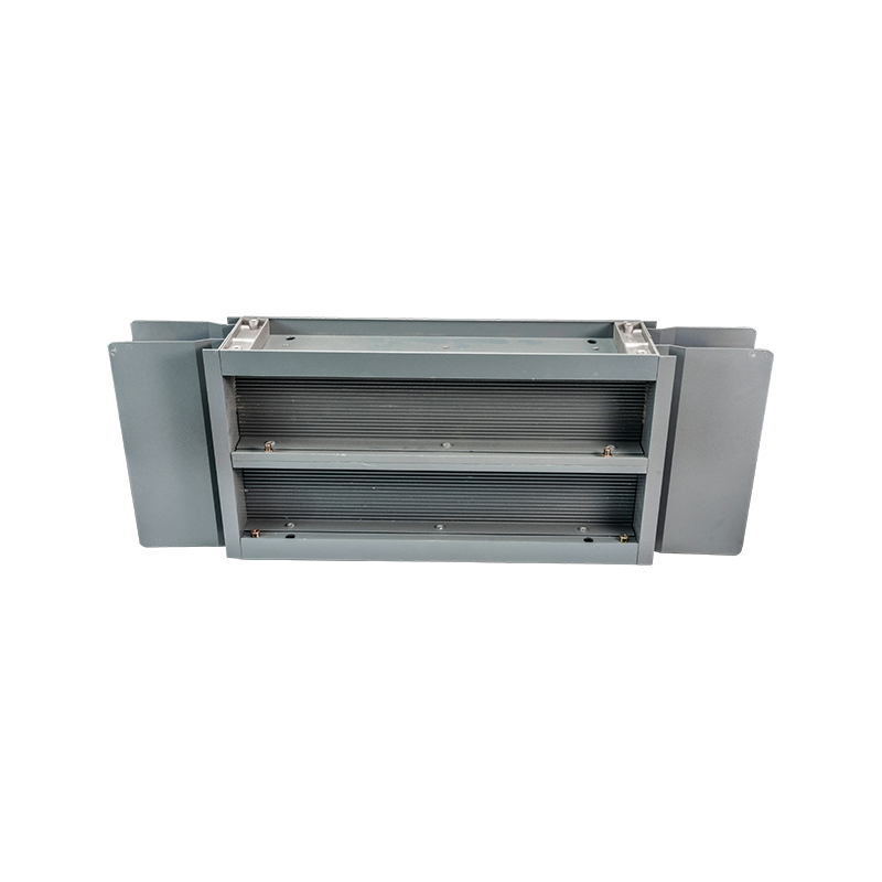
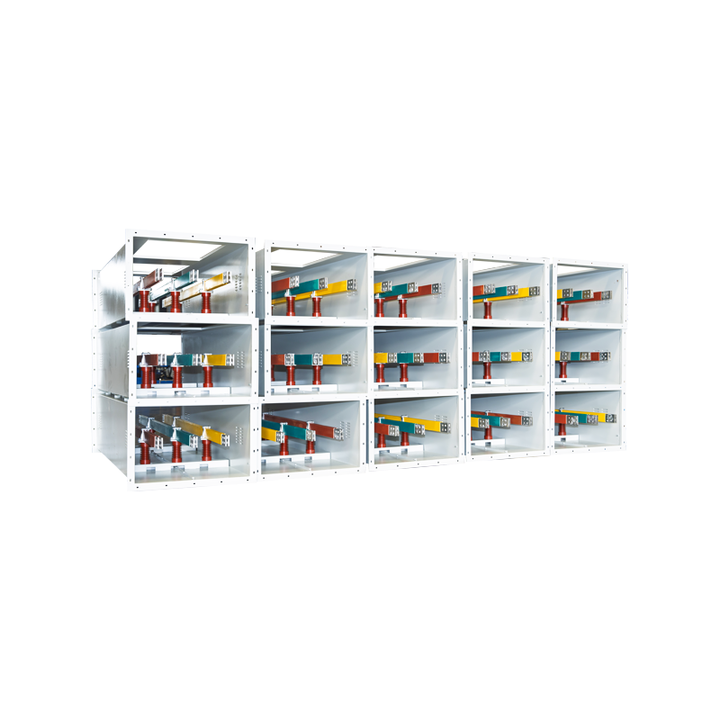
High-density Compact Busway
4. Dense Structural Design and Space Efficiency
The most visible advantage of a high-density compact busway is its efficient use of space. Traditional cable systems require multiple cables, cable trays, supports, bending radii, separation distances, and access clearances. As current capacity increases, the number and size of cables also increase. This can lead to crowded shafts, large cable trays, complicated routing, and difficult maintenance access.
A compact busway consolidates the conductors into a factory-engineered enclosure. The conductors are arranged in a multilayer dense configuration, reducing the amount of unused space between phases. This can reduce the overall installation footprint by up to approximately 50 percent compared with some conventional arrangements, depending on the project configuration and comparison basis.
The smaller footprint is beneficial in high-rise buildings, data centers, industrial plants, shopping complexes, transportation stations, and infrastructure facilities. Electrical shafts can be designed more efficiently, and valuable floor area can be reserved for production, storage, offices, or equipment.
Space efficiency also improves visual organization. A busway route presents a clean, continuous distribution path, whereas cable installations may contain numerous parallel cables and support systems. In facilities where appearance, accessibility, and orderly engineering are important, the compact busway can provide a more professional installation result.
The dense arrangement also contributes to mechanical stability. Closely supported conductors are less likely to move under electromagnetic forces during fault conditions. The enclosure and resin insulation work together to maintain the relative position of the conductors, helping the assembly withstand mechanical and electrical stress.
Space efficiency should not be considered only a matter of aesthetics. A smaller distribution route may reduce the size of electrical rooms, structural supports, fire protection zones, and service passages. These reductions can influence the total building design and may create measurable savings in construction materials and labor.
5. Epoxy Resin Vacuum Casting Technology
Epoxy resin casting is a defining feature of this compact busway. During production, the conductive assembly is placed into a casting system, and epoxy resin is introduced under controlled conditions. Vacuum-assisted processing helps reduce air pockets and internal voids. After curing, the resin forms a solid insulation body around the conductors.
A void-free insulation structure is important because air gaps can become areas of electrical stress concentration. Under high electrical stress, moisture, contaminants, and partial discharge may affect the long-term reliability of insulation. Vacuum casting helps create a more uniform dielectric structure and reduces the likelihood of defects caused by trapped air.
The cast-resin body also provides mechanical reinforcement. It holds the conductors in a fixed position and protects them against vibration, impact, humidity, and contamination. This is particularly useful in industrial environments where equipment may be exposed to dust, vibration, temperature variations, or elevated mechanical activity.
Epoxy resin insulation can also improve the system’s resistance to moisture compared with some exposed or loosely enclosed arrangements. The suitability of the product for a specific environment must still be confirmed through engineering evaluation, but the sealed cast structure offers a strong foundation for protected low-voltage distribution.
Controlled casting requires more than simply pouring resin around conductors. The manufacturer must manage material preparation, resin viscosity, conductor positioning, mold condition, vacuum level, curing temperature, curing time, and dimensional control. Variations in any of these factors may influence insulation quality, mechanical strength, and final product consistency.
For this reason, advanced manufacturing processes are central to the product’s value. The final busway is the result of material engineering, electrical design, mold technology, process control, testing, and inspection. A reliable cast-resin system depends on all of these elements working together.
6. Copper Conductors and Electrical Performance
The product uses high-purity copper conductors with tin plating. Copper is widely selected for busbar applications because of its high electrical conductivity, favorable mechanical properties, and established performance in power distribution systems.
High-purity copper helps reduce electrical resistance and power losses. Lower resistance can contribute to lower voltage drop along the distribution route and improved efficiency when the system is correctly sized and installed. This is important for large loads, sensitive electronic equipment, data center power systems, and production machinery.
Tin plating provides an additional protective surface. It helps reduce the effects of oxidation and supports more stable contact performance at joints and connection points. The plating process must be properly controlled so that the surface is uniform and compatible with the joint hardware and connection method.
The conductor cross-section, spacing, arrangement, and connection design are selected according to the rated current and thermal requirements. High-current systems must be designed to control temperature rise, maintain acceptable voltage drop, and withstand electromagnetic forces during short-circuit events.
The stated temperature rise limit below 70 K reflects the importance of thermal management. Excessive temperature can accelerate insulation aging, reduce contact reliability, and increase energy losses. The dense arrangement of conductors must therefore be balanced with effective heat transfer through the resin and enclosure.
Although compact busways place conductors close together, the integrated structure can provide a controlled thermal path. Heat can move from the conductors through the insulation and into the enclosure, where it can dissipate into the surrounding environment. Correct installation clearances and ambient conditions remain essential to achieving the expected thermal performance.
7. Aluminum Alloy Enclosure and Mechanical Protection
The enclosure is made from high-strength aluminum alloy profiles. Aluminum alloy offers a useful combination of low weight, mechanical strength, corrosion resistance, and manufacturability. Compared with heavier steel enclosures, an aluminum alloy structure can simplify handling and installation while maintaining suitable protection for the internal busbar assembly.
The enclosure protects the busway against accidental impact, external contamination, and contact with energized components. It also contributes to the overall rigidity of the system and helps maintain the geometry of the internal conductors.
In addition, the metal enclosure can support electromagnetic performance by providing a defined conductive boundary around the busbars. The detailed grounding and bonding arrangement must be completed according to the system design and applicable electrical requirements.
Aluminum alloy profiles can be manufactured with consistent dimensions and integrated connection features. This supports modular assembly, repeatable joint installation, and efficient on-site alignment. A well-designed enclosure also provides a practical surface for mounting brackets, supports, covers, and accessories.
The choice of enclosure material demonstrates the importance of considering the complete system rather than focusing only on conductor capacity. A busway must be strong enough to survive transportation, lifting, installation, operation, and maintenance. It must also provide a stable housing for insulation and connection components throughout the service life of the project.
8. Safety and Reliability Advantages
Electrical safety is one of the principal reasons to select a fully insulated compact busway. The cast-resin insulation prevents routine contact with energized conductors and reduces exposure to environmental contaminants. The enclosed structure also minimizes the possibility of accidental contact during ordinary building or equipment activities.
The close arrangement of phases and the use of internal phase barriers help control phase-to-phase spacing. Compared with systems that depend heavily on open air gaps, the compact insulated structure offers a more controlled internal environment.
The IP65 protection rating can provide strong protection against dust ingress and water jets when the system is correctly assembled and the joints, covers, and accessories are properly sealed. This feature is particularly valuable in industrial and service environments where airborne dust, humidity, or cleaning activity may be present.
The product’s short-time withstand current of 50 kA for 1 second indicates its suitability for demanding fault conditions within the stated design parameters. During a short circuit, conductors and supports experience considerable thermal and electrodynamic forces. The conductor arrangement, resin body, joints, and enclosure must work together to withstand these stresses.
The power-frequency withstand voltage of 3500 V for 1 minute is an important dielectric verification value. It demonstrates that the insulation system is designed to tolerate a specified test voltage for the required duration without breakdown under test conditions.
Fire performance is another important factor. Relevant insulating materials are designed to meet UL94 V-0 flame-retardant performance. This can help limit the spread of flame in the event of a localized ignition, although the complete installation must still comply with project fire safety requirements and building regulations.
The stated seismic capability up to intensity level 8 supports applications where the electrical distribution system must remain mechanically stable during significant ground movement. Seismic design must include the busway, supports, joints, building interfaces, and connected equipment rather than relying on the busway body alone.
9. Plug-In Distribution and Modular Expansion
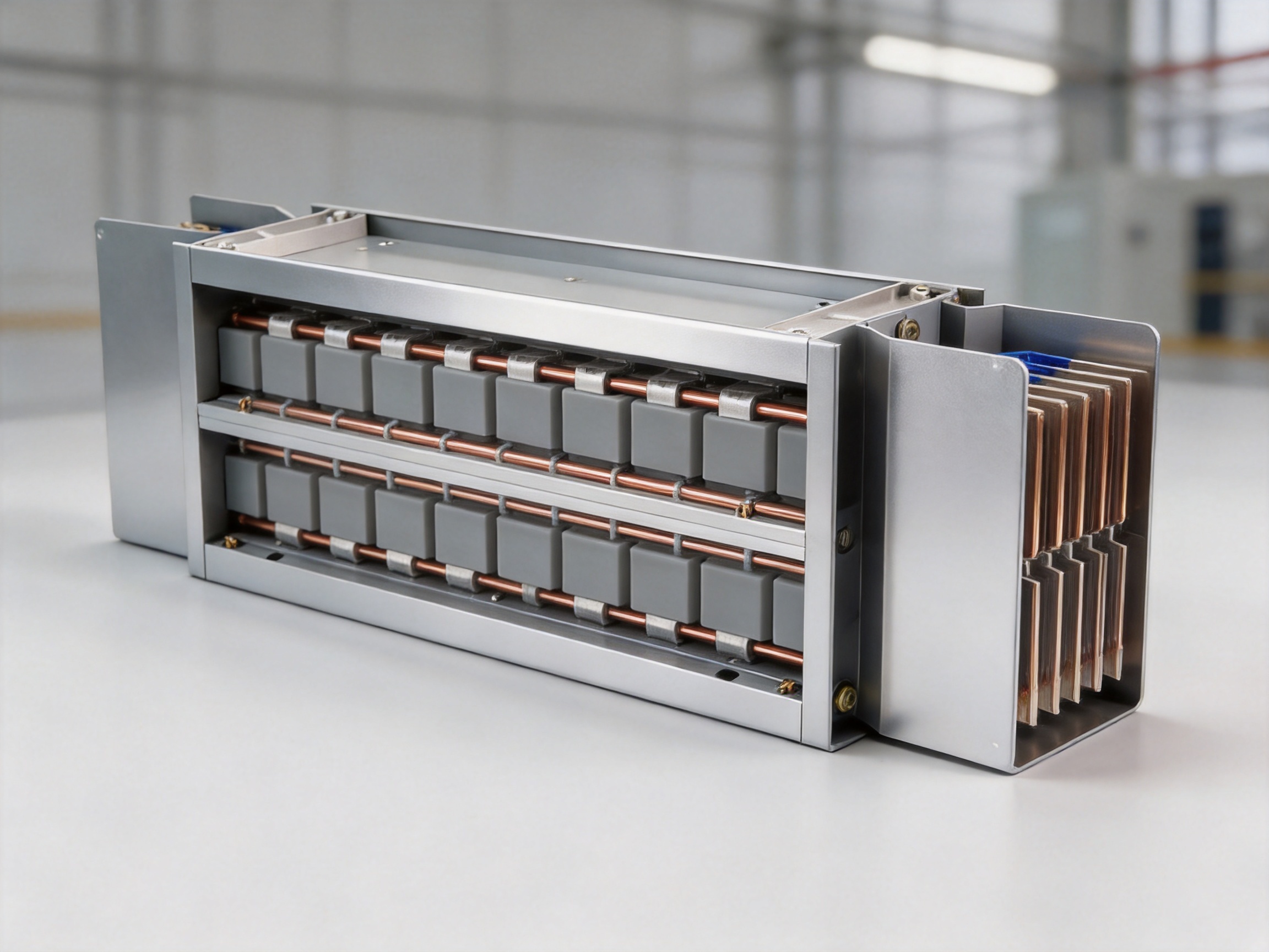
A major advantage of busway systems over fixed cable routes is the ability to distribute power through plug-in connection units. Tap-off boxes or plug-in units can be installed at selected locations along the busway. These units provide local power access without requiring a separate long cable route from the main distribution board.
Depending on the project design, plug-in points can be arranged at intervals of approximately 500 mm to 1000 mm. This creates a flexible distribution grid for equipment, workstations, production machines, or server racks. The exact spacing and operating conditions must be determined by the product configuration and the applicable safety procedures.
Modularity is particularly useful in facilities that change over time. A manufacturing plant may add a new machine. A data center may install additional cabinets. A commercial building may reconfigure tenant areas. A logistics facility may expand conveyor systems. With a suitable busway arrangement, new loads can be connected at available positions rather than requiring extensive rewiring.
Modular expansion can also shorten project schedules. Factory-produced busway sections are delivered in standardized lengths and assembled on site using designed joints and accessories. This can be more predictable than measuring, cutting, pulling, terminating, and testing numerous large cables in the field.
The modular concept also supports maintenance planning. Sections, joint covers, tap-off units, and accessories can be inspected systematically. If a component requires replacement, the work can often be limited to the relevant section, subject to the required isolation and safety procedures.
Any modification to an energized distribution system must be performed only by qualified personnel under an approved safety procedure. The flexibility of plug-in distribution does not remove the need for isolation, verification, protection against re-energization, and compliance with electrical regulations.
10. Comparison with Traditional Cable Systems
Traditional cable systems remain suitable for many applications, but they can become difficult to manage when current demand is high or when the route contains multiple branches. Large cable groups require trays, ladders, supports, separation, bending space, termination hardware, and extensive identification.
Installing high-current cables can also be labor intensive. Workers may need to transport heavy cables to the installation location, pull them through constrained routes, arrange them according to phase and circuit requirements, and complete numerous terminations. Each additional circuit increases the amount of field work.
A compact busway is largely prefabricated. Its conductors are assembled, insulated, enclosed, and tested in a controlled manufacturing environment. On site, installers focus on positioning, joining, supporting, connecting, and testing the sections. This can reduce installation time by approximately 30 to 50 percent compared with certain cable-based installations, although actual results depend on route complexity, project size, labor conditions, and site readiness.
The difference in maintenance is also significant. Cable systems may include many exposed or accessible terminations, while a sealed busway provides a more standardized arrangement. Routine inspection can be organized around joints, tap-off units, supports, and connection points.
Compact busways may have a higher initial material cost than some conventional cable solutions. However, the total project cost includes labor, supports, fireproofing, installation time, electrical room space, future modifications, and maintenance. When these factors are considered, the compact busway can provide a favorable life-cycle cost.
| Comparison Factor | Traditional Cable Installation | High-Density Compact Busway |
|---|---|---|
| Distribution footprint | Often large because of multiple cables and trays | Compact integrated route |
| Installation method | Field cable pulling and termination | Prefabricated sections with engineered joints |
| Expansion | May require additional cables and tray space | Plug-in units can support modular expansion |
| Route appearance | May contain numerous parallel cables | Clean and organized enclosed structure |
| Heat management | Depends on cable spacing and tray arrangement | Integrated conductor and enclosure design |
| Environmental protection | Depends on cable type and installation method | Cast resin and enclosure provide integrated protection |
| Maintenance access | Many cables and terminations may require tracing | Standardized sections, joints, and tap-off points |
| Future changes | Potentially complex and labor intensive | Modular approach supports more convenient changes |
11. Advantages over Conventional Air-Insulated Bus Duct
Compared with traditional air-insulated bus duct, a cast-resin compact busway provides a more enclosed insulation structure. Conventional air-insulated systems depend on carefully maintained air clearances and physical barriers. Their performance can be influenced by dust accumulation, humidity, foreign objects, and installation conditions.
The epoxy resin body of a cast-resin busway provides solid insulation around the conductors. This reduces dependence on open internal air space and creates a more stable dielectric environment. The enclosure and phase barriers add further protection.
The compact design can also reduce the overall size of the distribution system. Smaller dimensions may simplify shaft design and reduce the amount of structural support required. The lower installation volume can be especially valuable in high-rise construction and facilities with complex utility coordination.
Another advantage is environmental protection. A well-sealed compact busway can offer stronger resistance to dust and moisture than an exposed or loosely protected arrangement. This does not mean that every installation environment is automatically suitable. Corrosive chemicals, extreme temperatures, standing water, and unusual atmospheric conditions require specific evaluation.
The cast-resin design also reduces the likelihood of conductor movement. In a fault condition, the rigid insulation structure helps restrain the bars and distribute mechanical forces through the assembly. The result is a robust system designed for high-current operation and demanding service conditions.
These advantages position the compact busway as a strong alternative where safety, space efficiency, environmental protection, and modularity are more important than simply minimizing initial material cost.
12. Application in Data Centers
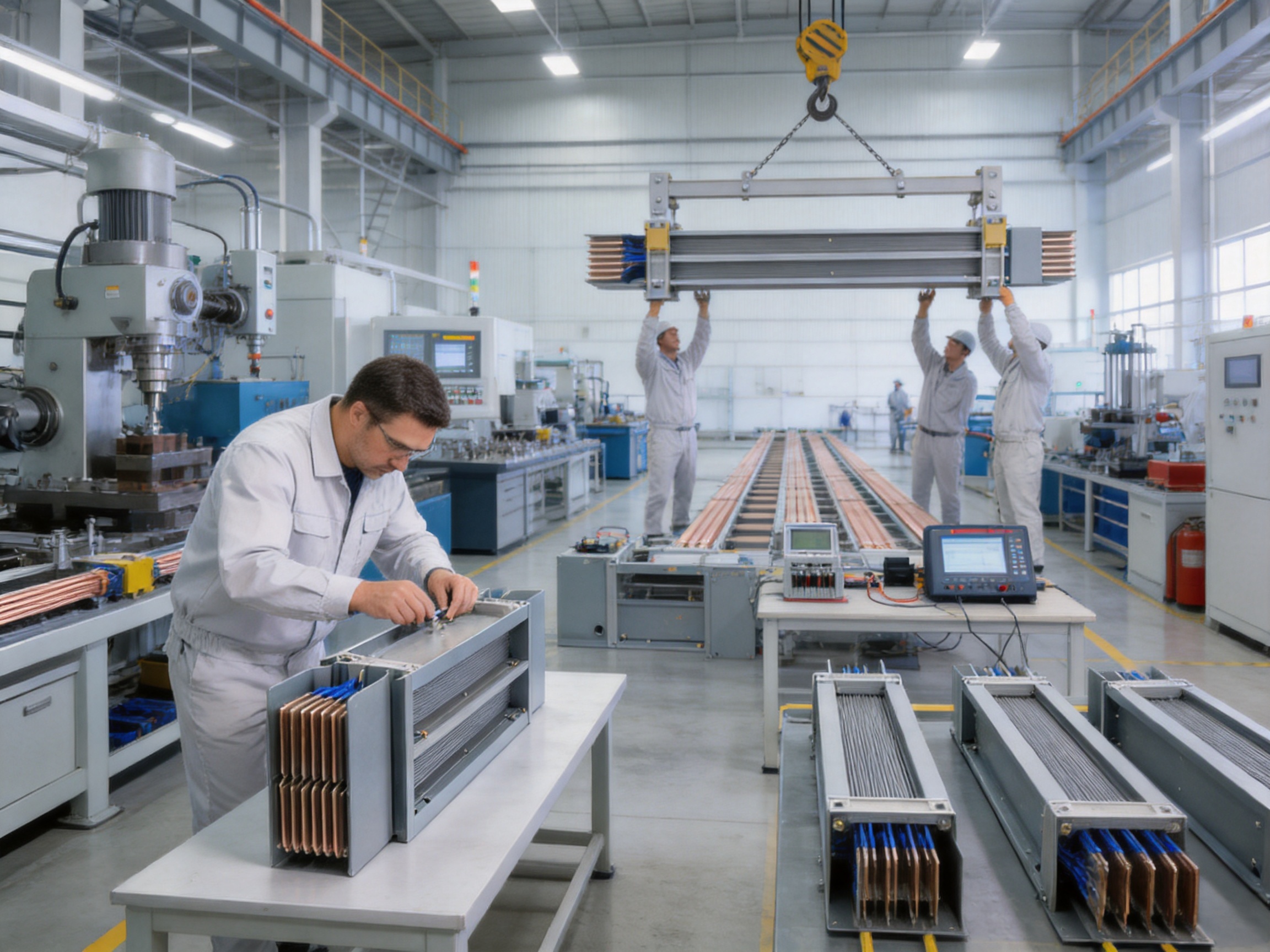
Data centers require reliable power distribution, high availability, organized equipment layouts, and the ability to expand as computing demand grows. High-density compact busway can serve as an efficient backbone between power distribution equipment and server cabinet areas.
Large data centers may require high current capacities, and a single busway run can be designed for current ratings reaching several thousand amperes. The product range up to 5000 A is suitable for many high-density distribution routes, subject to system design and load calculations.
Plug-in units allow server cabinets or equipment rows to receive power at multiple points. As the data center expands, additional tap-off boxes can be installed where permitted by the design. This supports phased construction and reduces the need to predict every future cabinet position at the beginning of the project.
Low impedance helps limit voltage drop along the route. Stable voltage is important for power supplies, cooling systems, monitoring equipment, and other sensitive data center loads. The busway must still be coordinated with transformers, switchgear, protective devices, standby generators, uninterruptible power supplies, and automatic transfer systems.
The compact structure also helps data centers use floor and ceiling space efficiently. A clean busway layout can improve access to server rows and reduce visual and physical congestion caused by extensive cable tray networks.
Reliability in data centers depends on the whole electrical system. Redundancy, selective coordination, grounding, protection, maintenance procedures, fire safety, and monitoring must be considered together with the busway specification.
13. Application in Industrial Manufacturing
Manufacturing plants often contain heavy machinery, motor loads, welding equipment, production lines, cranes, compressors, and automated systems. These loads may be distributed across a large facility and may change as production requirements evolve.
A compact busway can provide a continuous electrical route above production areas or along designated service corridors. Plug-in units can supply individual machines or groups of machines without requiring a new feeder cable for every adjustment.
The enclosed structure is valuable in industrial environments where dust, vibration, and accidental mechanical contact may be present. The cast-resin insulation and aluminum alloy enclosure provide a protective arrangement for the conductors, while the modular structure supports production-line changes.
High-current ratings are useful for centralized manufacturing equipment and process loads. The system can also be coordinated with motor control centers and local disconnecting equipment so that maintenance personnel can isolate individual machines safely.
Because manufacturing projects often operate under schedule pressure, installation speed is important. Prefabricated busway sections can reduce the amount of field fabrication and help the construction team complete power distribution in parallel with other building activities.
14. Application in Commercial Buildings and Infrastructure
Commercial buildings require flexible power distribution for lighting, heating, ventilation, air conditioning, elevators, retail spaces, offices, and tenant areas. A compact busway can be used in vertical risers, plant rooms, service corridors, and floor distribution zones.
In high-rise buildings, vertical busway risers may reduce shaft space compared with multiple cable groups. The standardized structure also simplifies coordination between floors. Tap-off units can supply floor distribution boards or local electrical rooms at defined locations.
Shopping centers, office complexes, hospitals, airports, and rail facilities may benefit from the clean appearance and organized routing of busbar trunking. The system can be integrated into the building’s architectural and mechanical layout more easily when its dimensions and connection points are established early in the design process.
Infrastructure facilities often require reliable power under challenging operating conditions. The protection rating, mechanical strength, insulation performance, and short-circuit withstand capability of the busway should be evaluated against the environmental and electrical requirements of each project.
For renovation projects, compact busway can also provide a practical solution where existing cable routes are overloaded or where building space is limited. A new route may be installed with less disruption than a large cable tray system, provided that structural access and shutdown planning are properly managed.
15. Manufacturing Strengths and Process Control
The quality of a high-current busway depends heavily on manufacturing discipline. Jiangsu Wopeng Power Technology Co., Ltd. has developed manufacturing capabilities focused on high- and low-voltage busbar systems, including epoxy resin vacuum-cast tubular busbars, low-voltage cast-resin busways, copper and aluminum tubular busbars, wind power tube busbars, compact busbar systems, and sliding contact line systems.
Founded in 2018, the company combines engineering, technical, production, and quality management personnel with experience in power equipment. This product range allows the company to understand busbar design across different voltage levels and application environments rather than treating low-voltage busway as an isolated product category.
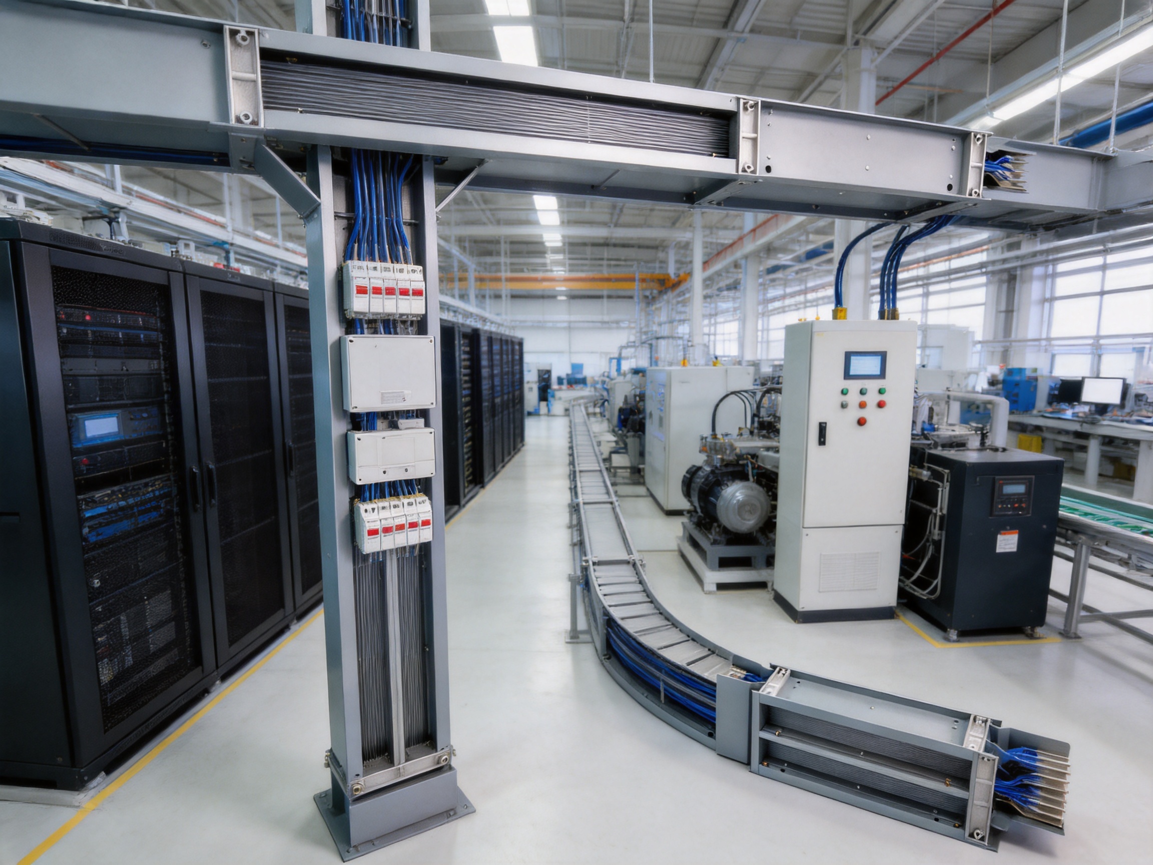
The company operates production lines equipped with vacuum casting systems, CNC machining equipment, and automated assembly technologies. Vacuum casting equipment supports the manufacture of dense epoxy insulation structures. CNC machining helps maintain accurate dimensions for enclosure components, connection parts, and mechanical interfaces. Automated assembly technologies improve repeatability and reduce variation in standardized production steps.
Manufacturing control begins with material selection. Conductors, resin, insulation components, aluminum alloy profiles, fasteners, barriers, joints, and accessory parts must meet defined technical requirements. Incoming material inspection helps confirm that production begins with qualified components.
Conductor preparation may include cutting, forming, surface treatment, tin plating, and dimensional inspection. Correct conductor dimensions are essential for current capacity, connection alignment, insulation thickness, and final assembly quality.
Resin processing requires controlled formulation and preparation. The resin and curing system must be mixed according to defined proportions and processed within appropriate temperature and viscosity ranges. Vacuum treatment helps remove trapped air and supports consistent encapsulation around the conductors.
Mold and tooling quality are also important. A mold must provide correct dimensions, sufficient rigidity, and reliable sealing during casting. Any dimensional deviation can influence insulation thickness, enclosure fit, joint alignment, or the final installation process.
Curing is a controlled process rather than a simple waiting period. The temperature and time profile must be managed to allow the resin to develop the required mechanical and electrical properties. Inadequate curing can affect strength and dielectric performance, while excessive or uneven curing may create internal stress.
After casting, the product undergoes dimensional finishing, enclosure assembly, installation of barriers and accessories, and mechanical inspection. The complete unit must be checked for appearance, dimensions, connection positions, surface quality, and assembly integrity.
16. Testing and Quality Assurance
Electrical distribution products must be verified through systematic testing. The company’s inspection program includes high-voltage tests, insulation tests, mechanical verification, and routine quality checks. These procedures help identify defects before the product leaves the factory.
High-voltage withstand testing verifies the dielectric strength of the insulation system under a specified test voltage. Insulation resistance testing provides additional information about the condition of the insulation and helps identify abnormal leakage paths or contamination.
Mechanical verification may include dimensional checks, enclosure inspection, joint evaluation, fastening inspection, and structural review. Mechanical quality is important because busway sections must align accurately during installation and must remain stable under operating and fault conditions.
Routine quality checks can include conductor resistance, phase identification, plating inspection, resin appearance, enclosure dimensions, accessory configuration, and packaging inspection. Consistent documentation improves traceability and supports project quality records.
Testing collaboration with third-party institutions can provide independent validation of safety and performance. Independent testing is particularly valuable for customers requiring project documentation, certification support, or confirmation of compliance with specified technical criteria.
Quality assurance should continue after production. Proper packaging protects the busway during transportation and storage. Installation instructions, joint procedures, torque requirements, inspection points, and commissioning records help maintain the product’s intended performance on site.
17. Engineering and OEM Support
Busway selection cannot be based only on current rating. A complete engineering solution should consider the electrical system voltage, load profile, fault level, route length, ambient temperature, installation orientation, support spacing, expansion joints, fire compartments, connection equipment, and maintenance access.
A capable manufacturer can support customers with product selection, route planning, current calculation, joint configuration, tap-off positioning, accessory selection, and technical documentation. OEM support is especially important when the busway must fit a customized building layout or integrate with non-standard equipment.
Custom solutions may involve conductor material, phase arrangement, enclosure dimensions, connection direction, section length, tap-off locations, support design, or environmental protection. A manufacturer with experience across multiple busbar product categories can often provide more informed engineering guidance.
Close communication between the manufacturer, electrical consultant, contractor, switchgear supplier, and end user reduces the risk of interface problems. Dimensions, connection details, delivery sequence, site conditions, and testing requirements should be confirmed before production.
For large infrastructure projects, documentation is also important. Typical documentation may include product drawings, technical data sheets, installation instructions, test reports, inspection records, packing lists, and operation or maintenance recommendations.
18. Installation Considerations
Successful installation begins with route verification. The contractor should confirm dimensions, elevations, support locations, access paths, lifting requirements, joint positions, and interfaces with switchboards or transformers. Small errors in route measurement can create difficulties when prefabricated sections arrive on site.
Busway sections should be stored in a clean, dry, and protected environment. Resin-insulated components and connection accessories should not be exposed unnecessarily to impact, standing water, chemicals, or uncontrolled contamination.
During installation, sections must be aligned carefully. Joints should be assembled according to the manufacturer’s instructions, and fasteners should be tightened using the specified method. Incorrect torque, damaged joint components, or poor alignment may affect electrical resistance, sealing, and mechanical stability.
Supports must be installed at the correct spacing and must be capable of carrying the system weight and expected mechanical loads. Vertical installations may require additional consideration for thermal expansion, seismic movement, building interfaces, and load transfer between floors.
After assembly, the system should be inspected before energization. Inspection may include visual checks, joint cover verification, conductor continuity, insulation resistance, phase identification, protective bonding, and withstand testing where required by the project.
Tap-off units and plug-in boxes must be installed in accordance with their intended orientation and rating. Protective devices should be coordinated with the busway capacity and downstream loads. Unauthorized modifications, drilling, cutting, or field alteration can compromise the insulation and enclosure system.
19. Operating Life and Maintenance
The compact busway is designed for long-term service, with a potential service life of up to 30 years under suitable operating, environmental, and maintenance conditions. Actual life depends on loading, ambient temperature, fault events, installation quality, environmental exposure, and maintenance practices.
Routine maintenance is generally focused on inspection rather than frequent replacement. Maintenance personnel may check joint covers, tap-off units, enclosure condition, support brackets, signs of overheating, abnormal noise, contamination, moisture, and mechanical damage.
Thermal imaging can be used as part of a planned electrical maintenance program to identify abnormal temperature at joints or connection points. Any unusual temperature rise should be investigated by qualified personnel before it develops into a serious failure.
Inspection intervals should be established according to the operating environment and the importance of the electrical system. Critical facilities may require more frequent inspection, monitoring, and testing than ordinary commercial installations.
A sealed cast-resin structure can reduce routine exposure of the conductors and may lower maintenance requirements compared with open systems. However, no electrical system is maintenance-free in an absolute sense. Connections, protective devices, supports, and interfaces still require professional inspection.
Where a fault or overload occurs, the system should be inspected before re-energization. The relevant section, joints, insulation, enclosure, and connected equipment should be evaluated for thermal or mechanical damage.
20. Energy Efficiency and Life-Cycle Value
Energy efficiency in electrical distribution depends on conductor resistance, loading, voltage drop, power factor, operating temperature, and system configuration. High-purity copper conductors and a low-impedance structure can help reduce distribution losses when the busway is correctly sized.
Compared with conventional cabling, the compact busway can reduce energy consumption by approximately 25 percent in some applications, according to the stated product positioning. Actual savings vary according to route length, conductor size, load profile, cable arrangement, operating hours, and comparison conditions.
Life-cycle value also comes from faster installation and easier expansion. A shorter construction period can reduce labor expenses and allow a facility to begin operation sooner. A modular distribution route can reduce the cost and disruption associated with future changes.
Reduced structural requirements may provide additional value. A compact route may require fewer supports and less space for cable trays, fireproofing, and service access. These benefits can be important in projects where construction materials and floor area represent a significant portion of the total cost.
The strongest economic analysis should compare complete installed systems rather than conductor prices alone. Material, labor, supports, testing, commissioning, maintenance, expansion, downtime risk, and building space should all be included in the evaluation.
21. Environmental and Application Limitations
Although compact busway provides strong protection, the product must be selected according to actual environmental conditions. Temperature, humidity, corrosive gases, chemical exposure, altitude, vibration, seismic movement, water risk, and installation location can influence product performance.
Projects in highly corrosive environments may require special enclosure finishes, material selection, or additional protection. Areas subject to flooding or continuous water exposure require a specific design review even when the product has a high ingress protection rating.
Ambient temperature affects current-carrying capacity and thermal performance. If the busway is installed near heat-producing equipment or in a poorly ventilated space, derating or additional thermal analysis may be required.
Electrical coordination is equally important. The rated current must match the expected continuous load and permissible overload conditions. The short-circuit withstand capability must be compatible with the available fault current. Protective devices must be selected to provide appropriate overload and short-circuit protection.
These considerations do not reduce the value of the compact busway. Instead, they emphasize that high-performance electrical equipment must be integrated into a properly engineered system.
22. Why Select an Experienced Busbar Manufacturer
Busbar systems operate under high electrical and mechanical stress. Manufacturer experience affects conductor design, insulation technology, enclosure construction, joint performance, testing, and technical support.
Jiangsu Wopeng Power Technology Co., Ltd. focuses on high- and low-voltage busbar system development and manufacturing. Its portfolio includes products extending from low-voltage cast-resin busways to 35 kV epoxy resin vacuum-cast tubular busbars. This broad range reflects experience with insulation coordination, high-current transmission, mechanical design, and specialized application requirements.
The company serves power generation, substations, wind energy, industrial manufacturing, rail transit, and large commercial facilities. Its products operate across more than 17 provinces and key industrial sectors, providing practical application experience in different operating environments.
The combination of engineering personnel, technical specialists, production professionals, modern equipment, and quality procedures supports the development of customized power transmission solutions. Customers can seek assistance not only with standard products but also with tailored OEM requirements and project-specific integration.
The manufacturing base includes vacuum casting systems, CNC machining equipment, and automated assembly technologies. These capabilities help improve dimensional accuracy, process repeatability, and product consistency.
For customers comparing suppliers, important evaluation factors include production capability, testing resources, engineering responsiveness, material control, quality documentation, project experience, delivery management, and after-sales support. A supplier that can address the complete project cycle can reduce technical and commercial risk.
23. Frequently Asked Questions
Q1: What is a high-density compact busway?
A high-density compact busway is an enclosed electrical distribution system in which copper or aluminum conductors are arranged closely together and protected by insulation and an external enclosure. The compact arrangement provides high current capacity in a relatively small installation footprint.
Q2: What voltage level is this product designed for?
This product is designed for low-voltage distribution systems with a rated voltage of AC 400 V/690 V. It is suitable for 0.4 kV power distribution applications when selected and installed according to the project requirements.
Q3: What current range is available?
The stated rated current range is 400 A to 5000 A. The correct rating depends on the connected load, operating conditions, ambient temperature, route configuration, and electrical design calculations.
Q4: Why is epoxy resin casting used?
Epoxy resin casting creates a solid insulation structure around the conductors. Vacuum-assisted casting helps reduce internal voids and supports a uniform insulation system. The resin also improves mechanical protection and resistance to dust, moisture, vibration, and accidental contact.
Q5: What conductor material is used?
The product uses high-purity copper busbars with tin plating. Copper provides high conductivity, while tin plating helps protect the conductor surface and support stable performance at connection areas.
Q6: Can the compact busway replace traditional cable systems?
It can serve as an alternative to cable systems in many high-current distribution applications, but the choice must be based on current, voltage, fault level, environmental conditions, route layout, installation method, budget, and applicable standards. Cables remain suitable for many specialized circuits.
Q7: Is the busway suitable for data centers?
Yes. Its high-current capability, low-impedance distribution path, compact structure, and modular plug-in units make it suitable for many data center applications. Redundancy, power quality, protection coordination, and availability requirements must be included in the overall design.
Q8: Can the system be expanded after installation?
The modular design allows tap-off units or plug-in boxes to be added at suitable points along the busway, subject to the product configuration and safety procedures. This makes the system more adaptable than a fixed cable route.
Q9: What protection rating does the product provide?
The protection rating can reach IP65. The actual rating depends on the complete assembly, including joints, covers, tap-off units, and installation quality. All components must be assembled correctly to maintain the intended protection level.
Q10: What fire performance is specified?
The relevant flame-retardant materials are designed to meet UL94 V-0 performance. Building fire safety, compartmentation, installation clearances, and local regulations must still be considered for the complete project.
Q11: How long can the busway operate?
The stated service life can reach up to 30 years under suitable operating and maintenance conditions. Actual service life depends on loading, environment, installation quality, fault events, and inspection practices.
Q12: What tests are performed before delivery?
Testing and inspection may include high-voltage withstand testing, insulation testing, mechanical verification, dimensional inspection, conductor checks, enclosure inspection, and routine quality control. Third-party testing cooperation may also be used for independent validation.
Q13: Can customized OEM solutions be provided?
Customized OEM solutions can be developed according to project requirements such as current rating, conductor arrangement, enclosure dimensions, tap-off locations, connection direction, section length, accessories, and environmental conditions. Technical details should be confirmed during the engineering stage.
Q14: What should customers provide when requesting a quotation?
Useful information includes rated voltage, required current, short-circuit level, route drawings, installation orientation, section lengths, tap-off positions, environmental conditions, connection equipment, quantity, delivery schedule, and applicable standards. Complete information improves quotation accuracy and reduces later design changes.
24. Conclusion
High-density compact busway technology provides a practical solution for modern low-voltage power distribution. Its dense conductor arrangement, epoxy resin vacuum casting, high-purity tin-plated copper conductors, aluminum alloy enclosure, flame-retardant barriers, and modular plug-in structure create a balanced combination of electrical capacity, safety, space efficiency, and flexibility.
The product supports rated currents from 400 A to 5000 A, AC 400 V/690 V operation, Class F insulation, IP65 protection, a 50 kA short-time withstand current for 1 second, and a 3500 V power-frequency withstand test for 1 minute. These characteristics make it suitable for data centers, manufacturing plants, commercial buildings, infrastructure facilities, and other high-current applications.
Compared with traditional cables and conventional air-insulated bus ducts, the compact busway can reduce installation space, simplify routing, accelerate construction, improve environmental protection, and support future expansion. Its value becomes even stronger when total life-cycle cost, maintenance, structural requirements, and facility adaptability are taken into account.
The performance of the system depends on engineering design and manufacturing quality. Vacuum casting, CNC machining, automated assembly, material inspection, electrical testing, mechanical verification, and third-party validation all contribute to dependable operation. Jiangsu Wopeng Power Technology Co., Ltd. combines these capabilities with experience across high- and low-voltage busbar systems and provides customized OEM support for demanding projects.
For project owners, designers, contractors, and equipment integrators, the selection of a compact busway should be based on a complete technical review rather than on current rating alone. When correctly specified, manufactured, installed, and maintained, a high-density compact busway can serve as a reliable, efficient, and adaptable backbone for modern electrical infrastructure.
References
1. IEC 61439, Low-Voltage Switchgear and Controlgear Assemblies, applicable sections concerning verification and performance.
2. IEC 60529, Degrees of Protection Provided by Enclosures, IP Code classification.
3. UL 94, Tests for Flammability of Plastic Materials for Parts in Devices and Appliances.
4. IEEE guidance on electrical power distribution system design, short-circuit evaluation, and equipment coordination.
5. General engineering principles for epoxy resin insulation, vacuum casting, thermal management, and low-voltage busbar trunking systems.
6. Manufacturer technical information for low-voltage cast-resin busways, copper busbars, aluminum alloy enclosures, plug-in distribution systems, and related electrical accessories.
Product: High-density Compact Busway



-
 +86-180 3625 3000
-
 admin@wpbusbar.com
-
 No. 8, Yanjin Road, Chengxi Industrial Park, Shanyang Town, Baoying County, Yangzhou City, Jiangsu Province, China
Copyright © Jiangsu Wopeng Power Technology Co., Ltd.
All Rights Reserved.
 Custom Insulated Bus Bar Manufacturer
Tubular Busbar System Factory
Custom Insulated Bus Bar Manufacturer
Tubular Busbar System Factory