

 EN
EN

 English
 русский
 Français
 Español
 عربى
عربى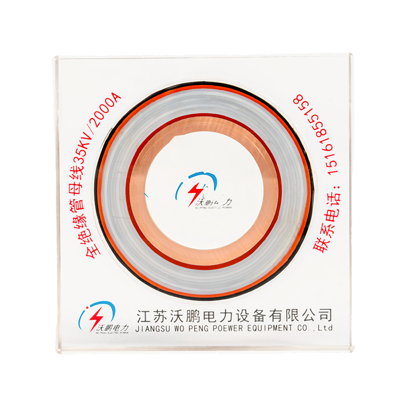
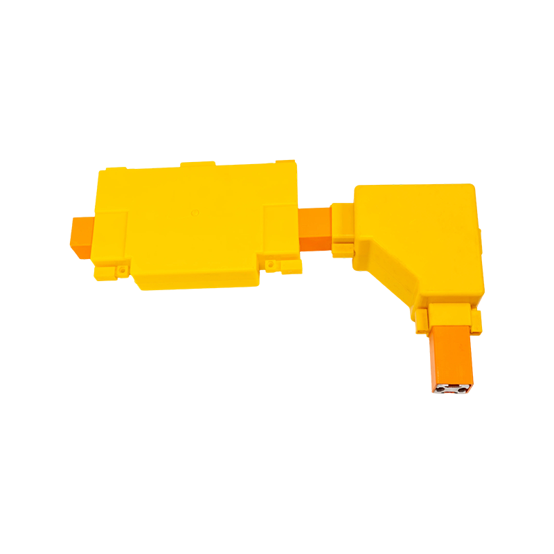

EPDM Silicone Rubber Tubular Bus Bar: Fully Insulated High-Voltage Power Transmission for Modern Electrical Systems
Content
- 1 1. What Is an EPDM Silicone Rubber Tubular Bus Bar?
- 2 2. Triple-Layer Co-Extrusion Technology
- 3 3. Electrical Performance and Electric Field Control
- 4 4. Environmental Resistance and Mechanical Durability
- 5 5. Terminals, Expansion Joints, and Intermediate Connections
- 6 6. Advantages Over Traditional Insulated Bus Bar Solutions
- 7 7. Main Applications
- 8 8. Typical Installation Arrangements
- 9 9. Manufacturing Strengths of Jiangsu Wopeng Power
- 10 10. Design and Selection Considerations
- 11 11. Installation, Commissioning, and Maintenance
- 12 12. Safety and Reliability Benefits
- 13 13. Why Choose a Specialized Tubular Busbar Manufacturer?
- 14 14. Frequently Asked Questions
- 14.1 Q1. What voltage range is suitable for an EPDM silicone rubber tubular bus bar?
- 14.2 Q2. What is the maximum current capacity?
- 14.3 Q3. Is the conductor made from copper or aluminum?
- 14.4 Q4. Can the product be installed outdoors?
- 14.5 Q5. Can it be used in coastal or chemical environments?
- 14.6 Q6. What is the benefit of triple-layer co-extrusion?
- 14.7 Q7. Why are stress cones used at the terminals?
- 14.8 Q8. Are the intermediate joints waterproof?
- 14.9 Q9. Is the bus bar more compact than an exposed conductor system?
- 14.10 Q10. How long can the product operate?
- 14.11 Q11. Does the product require special installation tools?
- 14.12 Q12. Can the manufacturer provide customized designs?
- 14.13 Q13. What information should be included in an inquiry?
- 14.14 Q14. Can the system be connected to an intelligent monitoring platform?
- 15 15. Conclusion
- 16 References
- 17 Product: EPDM Silicone Rubber Tubular Bus Bar
Reliable power transmission depends on more than conductor size alone. In medium- and high-voltage installations, the bus bar must carry substantial current, control the electric field, withstand mechanical stress, resist moisture and environmental aging, and remain safe throughout years of operation. The EPDM silicone rubber tubular bus bar is designed to address these requirements through a composite shielded insulation structure, tubular conductor technology, and carefully engineered joint and terminal systems.
Unlike a conventional exposed bus bar, this product integrates the conductor, conductor shielding, primary insulation, insulation shielding, metallic shielding, and outer protective sheath into a coordinated system. The result is a fully insulated tubular bus bar that supports secure installation in substations, industrial facilities, renewable energy plants, switchgear rooms, transformer connections, and other demanding power distribution environments.
The product is manufactured by Jiangsu Wopeng Power Technology Co., Ltd., a specialized busbar system manufacturer focused on high- and low-voltage power transmission equipment. Through polymer extrusion, vacuum casting, CNC machining, automated assembly, high-voltage testing, and standardized quality control, the company provides customized tubular busbar solutions for applications ranging from low voltage to 35kV.
1. What Is an EPDM Silicone Rubber Tubular Bus Bar?
An EPDM silicone rubber tubular bus bar is an insulated power transmission component that combines a rigid tubular copper or aluminum conductor with multiple layers of polymeric and metallic shielding. The conductor provides the low-resistance current path, while the insulation and shielding layers control electric field distribution and protect people and equipment from direct contact with energized metal.
The product is particularly suitable for medium- and high-voltage systems where ordinary cable arrangements, open bus bars, or large numbers of parallel conductors may create limitations in space, installation, heat dissipation, or maintenance. Its tubular configuration provides a high mechanical-strength current path, and its composite insulation system allows the bus bar to operate in locations where a bare conductor would be unsuitable.
The term “EPDM silicone rubber” describes the elastomeric insulation system used in the product. The primary insulation is based on ethylene propylene diene monomer, commonly known as EPDM, with silicone-related performance characteristics and protective polymer components selected for electrical insulation, flexibility, weather resistance, and long-term service. The exact material formulation and thickness are selected according to system voltage, current, environment, and project requirements.
1.1 Main Components
The bus bar is constructed from several functional layers. Each layer has a specific purpose, and the performance of the complete product depends on the compatibility and continuity of all layers.
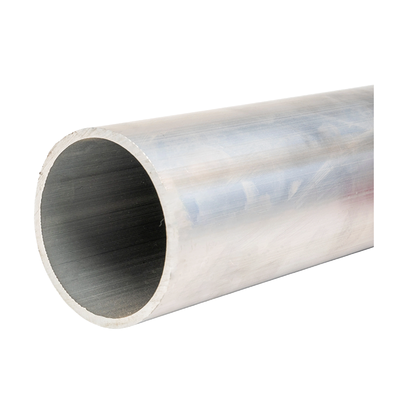
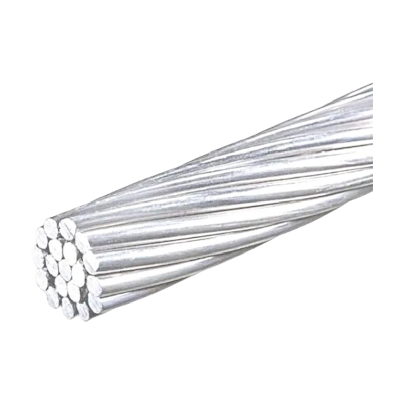
Tubular conductor: A solid copper or aluminum tube provides the primary current-carrying path. Copper is selected when high conductivity and compact dimensions are important, while aluminum can reduce weight and material cost in suitable applications.
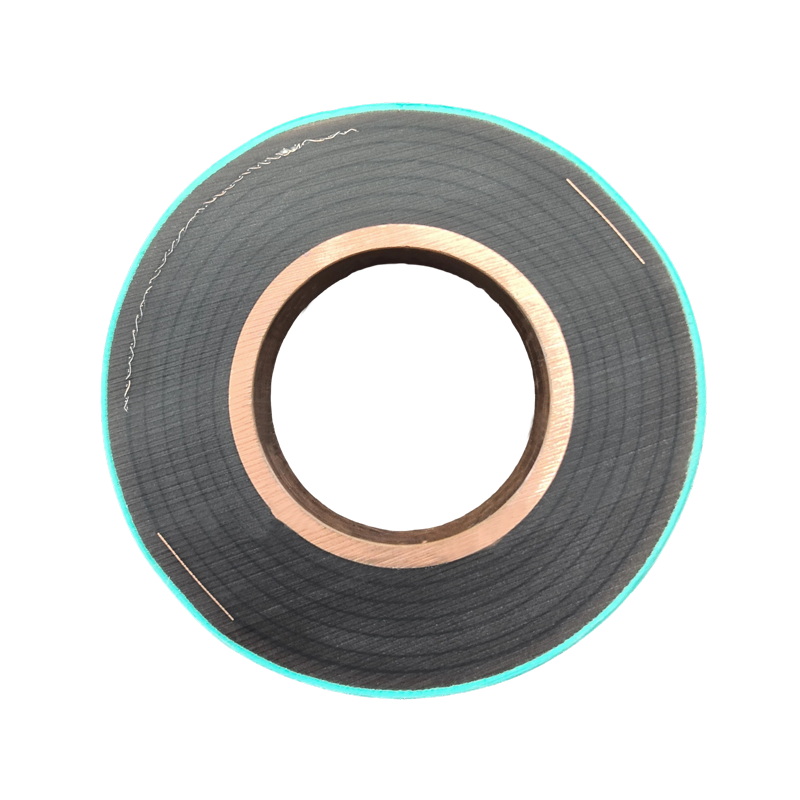
Conductor shield: A semiconductive shielding layer surrounds the conductor and helps smooth the conductor surface electrically. It reduces localized electric field concentration caused by surface irregularities, joints, or small dimensional variations.
Primary insulation: The EPDM-based elastomeric layer provides the main dielectric barrier between the energized conductor and the external shielding system.
Insulation shield: The external semiconductive layer maintains a controlled electrical interface around the insulation and helps ensure a stable electric field throughout the bus bar length.
Metallic shield: Copper foil or another specified metallic shielding component provides an additional shielding and grounding path when incorporated into the project design.
Outer sheath: A polyolefin polymer outer layer protects the internal structure against moisture, abrasion, contamination, ultraviolet exposure, and general handling damage.
Terminals and joints: Shielded prefabricated terminals, adapters, expansion connections, and intermediate joints complete the electrical and mechanical system.
1.2 The Purpose of a Composite Shielded Structure
In a medium- or high-voltage installation, the electric field must be managed continuously. If the field becomes concentrated at a sharp edge, irregular conductor surface, joint, termination, or damaged insulation point, partial discharge or corona may occur. Over time, these phenomena can degrade insulation and increase the risk of failure.
The composite shielded structure creates a controlled transition from the conductor to the surrounding environment. The conductor shield smooths the internal electrical surface, the insulation provides dielectric separation, and the insulation shield maintains a uniform external electrical boundary. The metallic shield and outer sheath then contribute to grounding, protection, and environmental resistance according to the system configuration.
Because the layers are produced as a coordinated structure, the bus bar is not merely a conductor placed inside a separate tube. It is an integrated insulated transmission system designed to maintain electrical continuity and insulation performance along the complete route.
2. Triple-Layer Co-Extrusion Technology
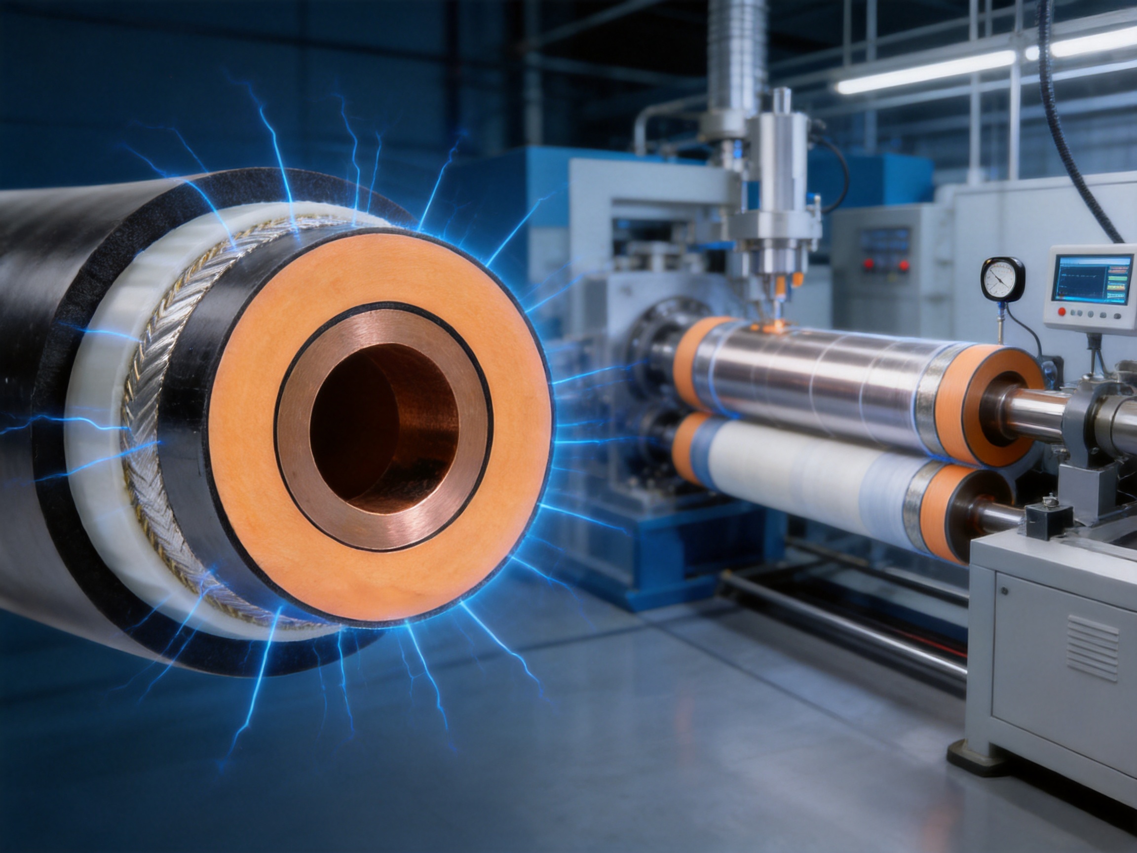
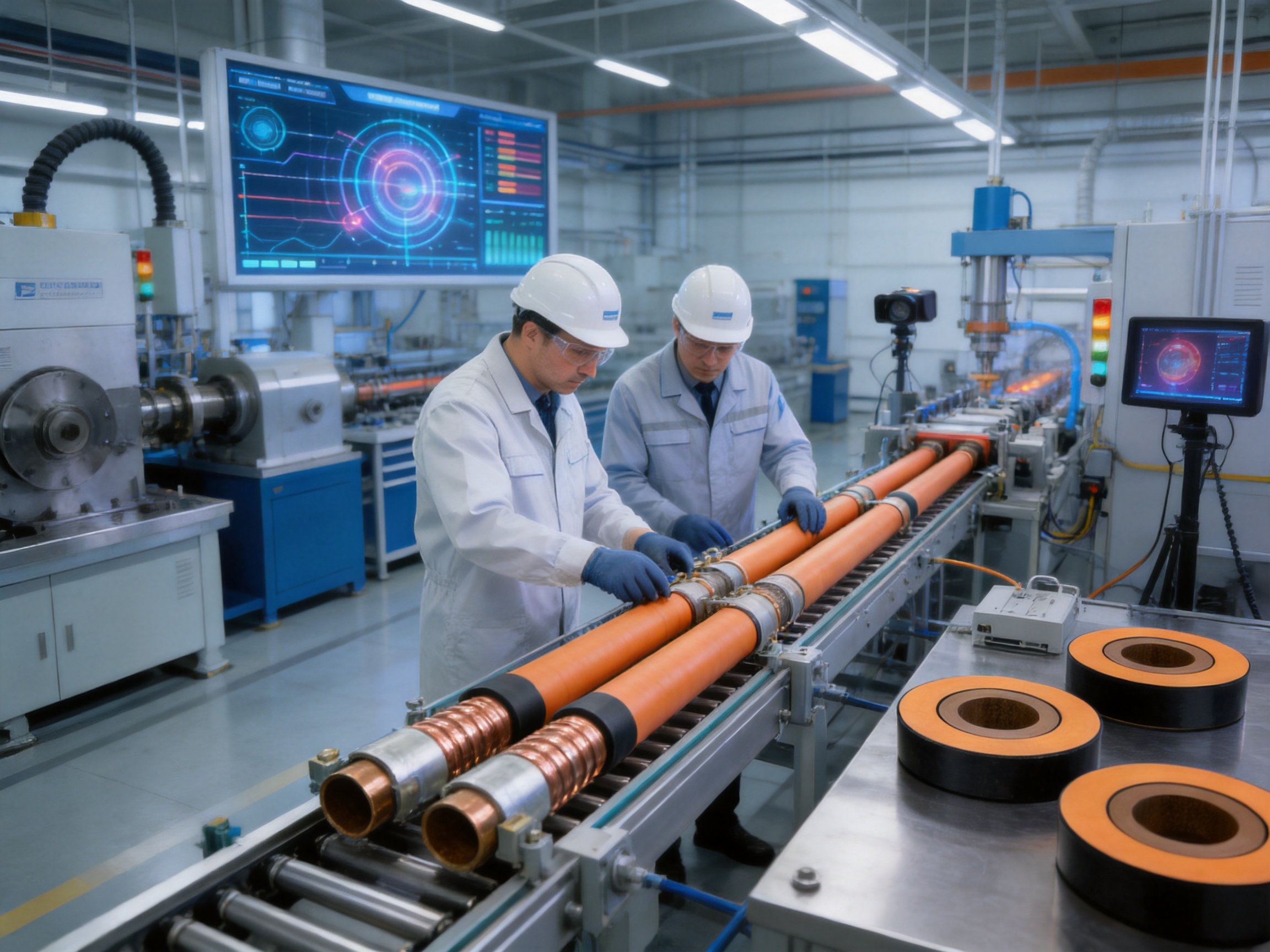
One of the principal manufacturing advantages of this tubular bus bar is triple-layer co-extrusion. During this process, the conductor shielding layer, the primary insulation layer, and the insulation shielding layer are extruded and formed in a controlled sequence during one continuous production operation.
Traditional multi-stage insulation processes may introduce dimensional variation, bonding inconsistencies, or small gaps between layers. Even when these defects are not visible, they can influence dielectric performance, partial discharge behavior, moisture resistance, and long-term reliability. Triple-layer co-extrusion is intended to reduce these risks by creating a tight interface between adjacent layers.
2.1 Tight and Gapless Interfaces
The interface between the conductor shield and the primary insulation must remain uniform. Similarly, the interface between the insulation and the external insulation shield must not contain voids or uncontrolled separation. Air pockets and gaps can produce local electric field intensification, especially under high voltage.
Co-extrusion helps form the layers together so that the interfaces are closely integrated. The process also improves concentricity and supports more consistent insulation thickness. This is important because a uniform radial structure contributes to stable dielectric performance around the entire circumference of the tubular conductor.
2.2 Process Control and Material Compatibility
Successful co-extrusion depends on accurate control of material temperature, extrusion speed, pressure, die geometry, curing conditions, and line tension. The conductor surface must also be clean and dimensionally consistent before the polymer layers are applied.
Jiangsu Wopeng Power combines polymer processing with conductor preparation, dimensional inspection, and subsequent assembly procedures. The company’s production capabilities include automated manufacturing technologies, CNC machining equipment, vacuum casting systems, and standardized inspection processes. This combination allows the conductor, insulation, terminal, and joint requirements to be considered as one engineered product rather than as independent components.
Material compatibility is equally important. The semiconductive shielding layers must work with the EPDM insulation, and the insulation must remain bonded or closely fitted without damaging the conductor or outer sheath. Production parameters are therefore selected according to conductor material, insulation thickness, voltage class, and required mechanical properties.
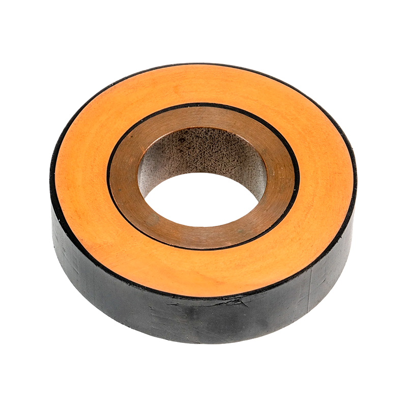
EPDM Silicone Rubber Tubular Bus Bar
3. Electrical Performance and Electric Field Control
The primary function of any bus bar is to transmit electrical current safely and efficiently. For medium- and high-voltage tubular bus bars, this function must be combined with reliable dielectric performance. The EPDM silicone rubber tubular bus bar is designed to support both requirements through conductor geometry, insulation material selection, shielding continuity, and terminal design.
3.1 Current-Carrying Capability
A tubular conductor provides a substantial conductive cross-section while maintaining a useful mechanical form. Copper tubular conductors are suitable for installations requiring high conductivity and strong connection performance. Aluminum tubular conductors may be selected where reduced weight, simplified handling, or economic optimization is important.
The final current-carrying capacity depends on conductor material, conductor dimensions, ambient temperature, installation arrangement, ventilation, enclosure conditions, permissible temperature rise, frequency, connection design, and applicable standards. Standard configurations may support currents up to approximately 3000A, while larger current ratings can be engineered through conductor sizing and thermal verification.
End connections deserve particular attention. A poorly designed transition can create additional resistance and local heating even when the central conductor is correctly sized. The terminal adapter is designed to connect the circular tubular conductor to a flexible expansion joint or a compatible connection end. This transition helps manage the change from a round conductor to a connection geometry suited to switchgear, transformer, or other equipment terminals.
3.2 Electric Field Distribution
The conductor shield and insulation shield work together to control the electric field. By providing smooth, continuous electrical surfaces, they reduce the effect of conductor irregularities and help limit localized stress within the insulation system.
The terminals use prefabricated cold-shrink structures and stress cones. A stress cone changes the geometric distribution at the end of the shielded insulation system, where the electric field would otherwise become concentrated. By gradually modifying the electrical geometry, the stress cone reduces field intensity at the voltage concentration point.
This approach can reduce the probability of corona and partial discharge when the terminal is correctly selected, installed, and tested. It also helps protect the insulation near the termination, which is one of the most sensitive areas in any high-voltage connection.
3.3 Dielectric and Partial Discharge Considerations
The insulation system is designed for high dielectric strength. A representative material performance value may reach a breakdown strength of approximately 25kV/mm, although the actual rated performance of a complete product depends on insulation thickness, electrical geometry, manufacturing tolerances, testing conditions, and the applicable technical standard.
It is important to distinguish material breakdown strength from the operating voltage rating of a finished busbar system. A project engineer must evaluate continuous operating voltage, lightning impulse withstand voltage, power-frequency withstand voltage, partial discharge levels, clearance, creepage, grounding, and installation conditions. These parameters should be confirmed through product drawings, test reports, and project-specific technical documentation.
The tight interfaces created by co-extrusion are particularly valuable for dielectric reliability. Voids, contamination, or uncontrolled interfaces can become sources of partial discharge. A controlled manufacturing environment, proper curing, dimensional inspection, and electrical testing are therefore essential to the performance of the finished product.
4. Environmental Resistance and Mechanical Durability
Power distribution equipment is often installed in environments that expose insulation to moisture, ultraviolet radiation, temperature changes, dust, industrial chemicals, salt, vibration, and mechanical impact. The outer insulation system of the EPDM silicone rubber tubular bus bar is designed to provide a protective barrier against these conditions.
4.1 Temperature Performance
EPDM-based elastomeric insulation can maintain useful flexibility and electrical performance across a broad temperature range. A representative operating range for the insulation system is approximately -40°C to 120°C, subject to the final design, conductor temperature, installation method, and specified thermal class.
The thermal performance of the complete bus bar is affected by both conductor heating and environmental heat transfer. A high-current installation must consider continuous load, short-circuit conditions, ambient temperature, enclosure ventilation, proximity to other equipment, and heat dissipation through terminals and joints.
Thermal expansion is another important consideration. Copper, aluminum, polymeric insulation, steel connection parts, and supporting structures have different coefficients of expansion. Flexible expansion joints and properly designed adapters help accommodate movement caused by temperature variation, reducing mechanical stress at equipment connections.
4.2 Weather and Ultraviolet Resistance
EPDM and compatible polymeric outer materials are known for resistance to ozone and ultraviolet exposure. This makes the product suitable for selected outdoor and semi-outdoor applications, including substations, renewable energy facilities, and industrial distribution systems.
Outdoor suitability must nevertheless be confirmed for each installation. Direct sunlight, altitude, coastal salt, pollution level, rain intensity, ice loading, wind, and local temperature extremes may influence the required sheath design and support arrangement. In coastal or chemically aggressive environments, the complete terminal and joint system must be evaluated together with the bus bar body.
4.3 Moisture and Water Resistance
The insulated tubular structure reduces the opportunity for moisture to contact the conductor. In addition, specially treated intermediate joints can provide short-term resistance to water immersion. This feature is valuable in cable trenches, underground routes, areas subject to flooding, and facilities where temporary water exposure may occur.
Water resistance does not eliminate the need for correct drainage, sealing, installation, and inspection. Joint surfaces must be clean, prepared correctly, and assembled according to the approved procedure. The complete system should be designed for the expected duration and depth of exposure rather than assuming unlimited underwater operation.
4.4 Chemical and Industrial Environments
The outer insulation system offers resistance to many common environmental influences, including ozone, ultraviolet radiation, moisture, and selected chemical contaminants. This supports applications in metallurgy, chemical processing, electronics manufacturing, transport infrastructure, and heavy industrial plants.
For aggressive chemicals, the compatibility of the EPDM insulation, polyolefin sheath, metallic shield, joint materials, and support components should be checked. A reliable manufacturer can recommend material combinations and protective measures based on the specific chemical exposure, temperature, concentration, and cleaning process.
5. Terminals, Expansion Joints, and Intermediate Connections
The bus bar body is only one part of a complete power transmission route. Terminals and intermediate joints must maintain current capacity, insulation continuity, electric field control, mechanical strength, and environmental protection. The product’s connection technology is therefore a major part of its value.
5.1 Prefabricated Cold-Shrink Terminals
Cold-shrink terminals are prefabricated components designed to simplify field installation. Unlike heat-shrink systems, they do not require an open flame or high-temperature heating operation. After positioning, the removable support structure is withdrawn, allowing the elastomeric terminal body to contract around the prepared connection.
The prefabricated structure provides controlled geometry at the termination. Its stress cone helps redistribute the electric field, while the sealing arrangement protects the interface from moisture and contamination. The terminal can be configured to suit the equipment connection, voltage class, conductor dimensions, and grounding requirements.
Cold-shrink installation can be advantageous in indoor electrical rooms, confined spaces, underground areas, and locations where hot work is restricted. It also supports a more repeatable installation process when technicians follow approved preparation and inspection procedures.
5.2 Terminal Adapters
The terminal adapter creates a smooth transition between the round tubular conductor and the flexible expansion joint or equipment connection. This transition is important because the conductor and the connected equipment may have different connection geometries.
A properly engineered adapter reduces abrupt changes in current flow and helps limit local resistance and temperature rise. It also provides a mechanical connection that can accommodate movement without placing excessive stress on the bus bar insulation or equipment bushing.
5.3 Intermediate Joints
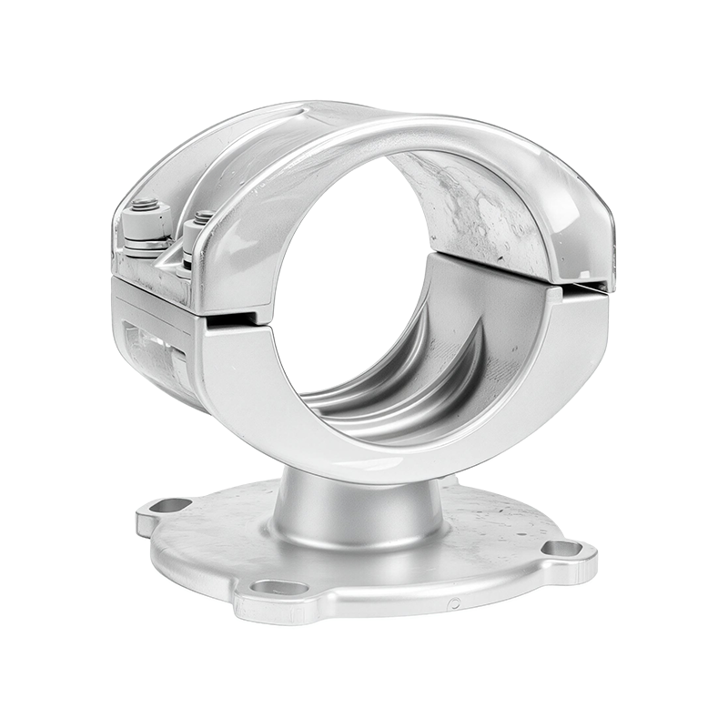
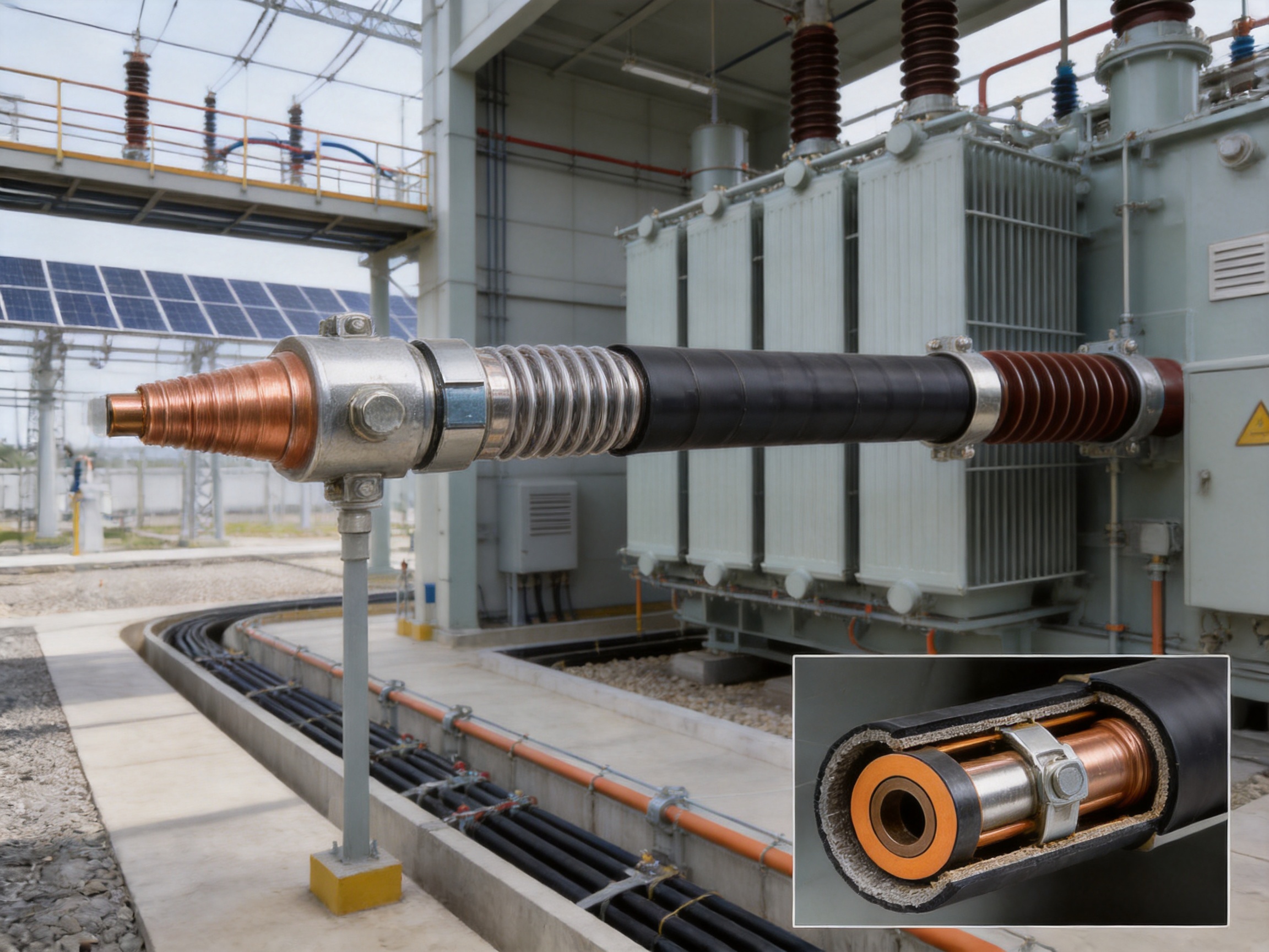
Intermediate joints connect separate bus bar sections into one continuous route. The conductor connection uses stainless steel inner sleeves that establish direct contact with the conductor ends. Two semicircular connecting bus bars are then installed externally, and four stainless steel C-clamps are tightened using specialized tools or molds.
This connection method is designed to maintain conductor contact, distribute mechanical pressure, and reduce the risk of conductor deformation. The use of dedicated tooling improves repeatability during installation. After the conductor connection is completed, the joint insulation and shielding components are assembled to restore the fully shielded structure.
The joint is compact, which helps reduce the space required in cable trenches, switchgear rooms, transformer connection areas, and other congested installations. With special waterproof treatment, the joint can also support short-term operation while submerged, provided that the approved product design and installation procedure are followed.
5.4 Why Joint Quality Matters
Joints and terminals are common points of electrical stress, mechanical movement, and heat concentration. A connection with inadequate contact pressure may create resistance and overheating. A poorly prepared insulation interface may cause partial discharge. An incomplete shield connection may create an uncontrolled electric field. A defective seal may permit moisture to enter the system.
For these reasons, the manufacturer must control not only the extrusion process but also conductor machining, connection preparation, component dimensional accuracy, assembly sequence, and final testing. Jiangsu Wopeng Power uses CNC machining, standardized assembly, high-voltage testing, insulation testing, mechanical verification, and routine quality checks as part of its production and inspection activities.
6. Advantages Over Traditional Insulated Bus Bar Solutions
The EPDM silicone rubber tubular bus bar competes with several types of power transmission systems, including bare tubular bus bars, PVC-insulated bus bars, ceramic-insulated bus bars, conventional cable arrangements, and some rigid busway products. Each technology has a suitable application, but the composite shielded tubular structure offers a balanced combination of insulation, flexibility, environmental resistance, current capacity, and compact routing.
| Performance Factor | EPDM Silicone Rubber Tubular Bus Bar | PVC-Insulated Bus Bar | Ceramic-Insulated Bus Bar | Exposed Tubular Bus Bar |
|---|---|---|---|---|
| Insulation performance | High-performance composite insulation with conductor and insulation shielding | Suitable for selected lower-stress applications but more limited at elevated temperatures and outdoor exposure | Very high dielectric capability but dependent on rigid ceramic components | No continuous external insulation unless additional barriers are installed |
| Weather resistance | Strong resistance to ultraviolet radiation, ozone, moisture, and general weathering | More vulnerable to ultraviolet aging and environmental degradation | Good environmental stability but vulnerable to impact and brittleness | Requires large clearances and protection from contamination and accidental contact |
| Mechanical flexibility | Elastomeric insulation and flexible connection options accommodate installation movement | Moderate, depending on construction and temperature | Low because ceramic parts are rigid and brittle | Rigid conductor system with movement handled by dedicated fittings |
| Joint design | Shielded cold-shrink terminals and compact protected intermediate joints | Depends heavily on external accessories and installation practice | Requires precise rigid assembly and careful handling | Open or screened connections require substantial clearance and protection |
| Space efficiency | Compact, fully insulated routing with reduced clearance requirements | Compact in suitable voltage and current ranges | Can require more rigid support and clearance arrangements | Requires greater phase-to-phase and phase-to-ground clearances |
| Typical service life | Approximately 25–35 years when correctly designed, installed, and maintained | Approximately 10–15 years in demanding environments, depending on material and exposure | Approximately 20–25 years, subject to mechanical and environmental conditions | Highly dependent on contamination, corrosion, and maintenance conditions |
6.1 Compared with PVC-Insulated Products
PVC insulation can be economical and practical in many low-voltage applications, but it may have reduced resistance to ultraviolet exposure, elevated operating temperature, and certain harsh environments. EPDM-based insulation generally provides greater flexibility and more robust resistance to ozone and weathering.
For medium- and high-voltage applications, the composite shielded design is also significant. A simple insulating layer without a coordinated conductor shield and insulation shield may not provide the same level of electric field control. The EPDM tubular bus bar is therefore suited to applications where insulation reliability and environmental durability are priorities.
6.2 Compared with Ceramic-Insulated Systems
Ceramic insulation can offer excellent dielectric strength and environmental stability. However, ceramic is rigid and can be vulnerable to impact, vibration, and mechanical shock. Installation often requires careful alignment and robust support structures.
The elastomeric insulation of the EPDM tubular bus bar provides greater tolerance for handling, routing, vibration, and thermal movement. It is less brittle than ceramic and can be integrated with flexible expansion joints. This makes it attractive for industrial facilities, transformer connections, wind power systems, and routes where equipment movement must be accommodated.
6.3 Compared with Exposed Bus Bars
Exposed bus bars can provide excellent current capacity and straightforward visual inspection, but they require substantial clearance and additional protection against accidental contact, contamination, animals, moisture, and foreign objects. Their installation may also require larger electrical rooms or outdoor structures.
A fully insulated tubular bus bar reduces the risk associated with direct contact and allows more compact routing. It is especially useful in cable trenches, cable mezzanines, switchgear connection areas, and locations where space is limited or full insulation is required.
6.4 Compared with Conventional Cable Solutions
Cables are flexible and widely available, but high-current cable systems may require multiple parallel runs, extensive support, complex termination arrangements, and careful phase spacing. Parallel cable installations can also occupy considerable space and require coordinated thermal analysis.
A tubular bus bar offers a defined mechanical route, high current capacity, and compact connection arrangement. Its rigid conductor can simplify alignment between transformers and switchgear, while expansion joints help accommodate movement. The best solution depends on route length, current, voltage, installation environment, bending requirements, and project economics.
7. Main Applications
The product is designed for power systems that require a dependable, insulated, and compact connection between major electrical assets. Its applications include both indoor and outdoor systems, provided that the product configuration matches the environmental and electrical requirements.
7.1 Substations and Switchgear Rooms
In substations, tubular bus bars can connect power transformers to medium-voltage or low-voltage switchgear, circuit breakers, protection equipment, and distribution cabinets. The fully insulated structure is useful where the equipment layout is compact or where exposed conductors would require excessive clearance.
Connections between a main transformer and a control or switchgear room are among the most common arrangements. The bus bar can be routed directly from the transformer’s low-voltage or medium-voltage terminals to the switch cabinet, creating a clear and organized connection path.
7.2 Cable Trenches and Cable Mezzanines
Bus bars may be routed through underground cable trenches or cable mezzanines. This arrangement can connect transformers to switchgear or link multiple switch cabinets. The fully insulated design is particularly useful in locations where wiring space is difficult, where access is restricted, or where several power routes must be arranged in a limited area.
Waterproofed joints can provide an additional level of protection in trench environments. However, drainage, support spacing, ventilation, and inspection access must still be incorporated into the civil and electrical design.
7.3 Industrial Plants
Metallurgical plants, chemical facilities, electronic manufacturing plants, and other industrial sites often require high-current distribution in challenging environments. The EPDM insulation system can help withstand heat variation, humidity, ozone, ultraviolet exposure, dust, vibration, and selected corrosive conditions.
Industrial installations also benefit from compact routing. By reducing the clearance requirements associated with open conductors, the bus bar may allow more efficient use of electrical rooms and equipment corridors. Its robust mechanical construction can support long-term operation when correctly mounted and protected from excessive external loads.
7.4 Renewable Energy Facilities
Solar power stations and wind power facilities contain distributed generation equipment, transformers, collection systems, and grid connection equipment. Tubular bus bars can connect generators, transformers, switchgear, and distribution assemblies where high current and environmental exposure must be managed together.
Wind power applications may involve vibration, temperature changes, restricted maintenance access, and equipment movement. Flexible expansion joints and carefully designed terminals help manage these conditions. The final design must account for tower geometry, vibration levels, cable or busbar support, and the movement of connected equipment.
7.5 Rail Transit and Large Commercial Facilities
Rail transit systems and large commercial facilities depend on reliable power distribution for traction, ventilation, lighting, safety systems, and mechanical equipment. Compact insulated busbar routes can help organize high-current connections in substations, service rooms, and equipment areas.
In commercial and public infrastructure, the fully insulated structure can also support safety objectives by reducing the risk of accidental contact and helping maintain orderly equipment layouts.
8. Typical Installation Arrangements
The tubular bus bar can be configured according to the layout of the transformer, switchgear, cable route, and building structure. Four representative arrangements demonstrate its flexibility.
8.1 Transformer-to-Control-Room Connection
In this arrangement, the bus bar runs directly from the main transformer terminals to the switch cabinet terminals in the control room. It is suitable for large currents and creates a direct, visually organized connection.
The route may use a fully insulated or semi-insulated configuration where permitted by the project design. A fully insulated product is generally preferred when the route passes through occupied areas, confined spaces, or locations requiring enhanced protection.
8.2 Route Through a Cable Trench
The bus bar may pass through an underground cable trench before connecting to switchgear. This arrangement keeps the power route below floor level and can be useful when overhead routing is not practical.
The design should include support brackets, joint access points, drainage provisions, thermal considerations, and protection against construction debris. The bus bar should not be used as a structural support for unrelated equipment or subjected to loads beyond its approved installation limits.
8.3 Route Through a Cable Mezzanine
A cable mezzanine can provide an elevated route between switchgear sections, transformers, and other equipment. This solution is useful in facilities where the floor area is limited or where multiple levels of power distribution are required.
The compact size of shielded tubular bus bars can simplify coordination with ventilation ducts, fire protection systems, structural members, and other services. Accurate route drawings and factory-engineered lengths help reduce field modification.
8.4 Intelligent Monitoring Arrangement
Modern tubular busbar systems can be integrated with monitoring solutions that collect operational information. Depending on the project, monitored parameters may include temperature, load current, insulation condition, joint status, and other technical data.
Jiangsu Wopeng Power has developed monitoring concepts for intelligent and unmanned supervision of multiple tubular busbar parameters. Such systems can support condition-based maintenance, early warning, trend analysis, and remote operational management. The scope of monitoring should be defined according to the voltage level, criticality, communication protocol, and protection requirements of the installation.
9. Manufacturing Strengths of Jiangsu Wopeng Power
A high-voltage busbar is a customized engineered product rather than a simple standardized metal component. Its reliability depends on design capability, material control, manufacturing accuracy, testing discipline, and field support. Jiangsu Wopeng Power Technology Co., Ltd. was founded in 2018 as a high-tech enterprise specializing in high- and low-voltage busbar systems.
9.1 Specialized Product Portfolio
The company’s product portfolio covers multiple power transmission technologies. It includes 35kV epoxy resin vacuum-cast tubular busbars, low-voltage cast-resin busways, copper and aluminum tubular busbars, wind power tubular busbars, compact busbar systems, and sliding contact line systems.
This broad portfolio gives the engineering team experience with different conductor materials, insulation systems, voltage levels, current ratings, connection methods, and installation environments. Customers can therefore evaluate related technologies through one specialized busbar manufacturer rather than coordinating separate suppliers for every application.
9.2 Engineering and Customization Capability
Each project may require a different conductor size, voltage class, route geometry, terminal type, joint location, support system, expansion allowance, grounding arrangement, and environmental protection level. Wopeng’s engineering team works with customers to develop customized OEM solutions based on these requirements.
Customization may include copper or aluminum conductors, different insulation thicknesses, terminal adapters, flexible expansion joints, special joint arrangements, monitoring provisions, and dimensional adaptations for transformer or switchgear connections. The final design should be confirmed through approved drawings and technical specifications before production.
9.3 Modern Production Equipment
The company operates production lines equipped with vacuum casting systems, CNC machining equipment, and automated assembly technologies. Vacuum casting is particularly important for cast-resin products, where the removal of air and controlled resin processing contribute to insulation quality. CNC machining supports accurate conductor and connection component dimensions.
Automated or standardized assembly helps reduce variation between products. It can improve repeatability in the preparation of conductor interfaces, installation of shielding components, fitting of terminal parts, and tightening of connection hardware.
9.4 Quality Management and Testing
Every power transmission product should be subjected to inspections appropriate to its design. Wopeng’s quality procedures include high-voltage tests, insulation tests, mechanical verification, and routine quality checks. Cooperation with third-party testing institutions provides additional independent validation of safety and performance.
Testing may cover conductor continuity, insulation resistance, power-frequency withstand, partial discharge, dimensional accuracy, mechanical strength, temperature rise, joint performance, and environmental characteristics. The exact test program depends on the voltage class, product type, customer specification, and applicable national or international standards.
Quality control begins with incoming materials and continues through conductor preparation, extrusion, curing, assembly, electrical testing, packaging, and shipment. Traceability is valuable because it enables the manufacturer to associate materials, process records, inspection results, and product identification with each delivered busbar system.
9.5 Field-Oriented Product Development
A product can achieve excellent laboratory results yet create problems if it is difficult to install or maintain in the field. Wopeng’s focus on compact joints, prefabricated cold-shrink components, dedicated connection tools, and practical routing arrangements reflects the importance of installation conditions.
Field-oriented engineering can reduce the need for on-site modification and help technicians complete connections in confined spaces. It can also improve consistency between the factory design and the installed system, which is especially important for high-voltage insulation and shield continuity.
10. Design and Selection Considerations
Choosing an EPDM silicone rubber tubular bus bar requires more than specifying a voltage and current value. A complete technical inquiry should describe the electrical system, physical route, environment, connection equipment, and expected operating conditions.
10.1 Voltage Level
The product is commonly considered for medium- and high-voltage systems in the range of 10kV to 35kV, with higher-voltage options subject to customized engineering. The rated voltage, insulation level, power-frequency withstand voltage, lightning impulse withstand voltage, and partial discharge requirements must be clearly identified.
10.2 Current Rating and Temperature Rise
Required continuous current, short-time current, peak withstand current, fault duration, ambient temperature, installation altitude, enclosure conditions, and allowable temperature rise should be provided. The conductor cross-section and connection design must be verified together because terminal and joint resistance can affect the overall thermal performance.
10.3 Conductor Material
Copper is often selected for high conductivity, compact dimensions, and robust connection performance. Aluminum can be appropriate where weight and material cost are important. The choice affects conductor size, connection technology, surface treatment, thermal behavior, and installation handling.
10.4 Route Geometry
Engineers should provide the complete route, including straight lengths, bends, elevations, equipment interface positions, joint locations, support points, and expansion requirements. Factory-manufactured sections can be prepared to suit the route, reducing the amount of field cutting or modification.
10.5 Environmental Conditions
The manufacturer should be informed about indoor or outdoor installation, ultraviolet exposure, pollution level, humidity, water immersion risk, coastal salt, chemical contaminants, vibration, altitude, temperature range, and fire safety requirements. These conditions influence the outer sheath, joint protection, support materials, and testing requirements.
10.6 Grounding and Shielding
The metallic shield and external shielding system must be connected according to the project’s grounding design. Shield continuity, grounding points, circulating current considerations, and protection against induced voltage should be reviewed by the electrical engineer.
10.7 Maintenance Access
Although a fully insulated tubular bus bar requires less exposure protection than a bare conductor, inspection access remains important. Terminals and joints should be accessible for visual inspection, thermal scanning where appropriate, shield continuity verification, and future maintenance.
11. Installation, Commissioning, and Maintenance
Correct installation is essential to achieving the performance of a high-voltage insulated busbar. The installation team should use approved drawings, manufacturer instructions, certified tools, and trained personnel.
11.1 Pre-Installation Inspection
Before installation, inspect the busbar sections, terminals, joints, outer sheath, conductor ends, identification marks, and packaging. Check for impact damage, moisture ingress, contamination, deformation, or missing components. Confirm that the product dimensions and connection arrangements match the approved drawings.
11.2 Handling and Storage
Busbar sections should be lifted and supported according to the manufacturer’s instructions. Excessive bending, dragging, sharp impact, and unsupported weight can damage the outer sheath or internal insulation. Components should be stored in a clean, dry location protected from direct sunlight, chemicals, and construction traffic.
11.3 Joint Preparation
Joint installation requires clean conductor surfaces, accurate alignment, correct sleeve positioning, and controlled tightening of the C-clamps. Specialized tools or molds should be used to achieve the specified connection geometry and pressure.
The insulation and shielding components must be installed in the correct sequence. Any contamination, foreign material, moisture, or damage at the interface can compromise dielectric performance. Shield continuity and grounding connections should be checked before the joint is enclosed.
11.4 Testing Before Energization
Before energization, the installed system should undergo the tests required by the project and applicable standards. These may include insulation resistance, conductor continuity, shield continuity, power-frequency withstand, partial discharge, phase identification, grounding verification, and visual inspection of terminals and joints.
Test results should be documented and compared with the manufacturer’s acceptance criteria. If a test result is abnormal, the system should not be energized until the cause has been identified and corrected.
11.5 Routine Maintenance
Routine maintenance may include visual inspection, checking supports and fasteners, inspecting joint and terminal areas, monitoring temperature, verifying grounding connections, and reviewing intelligent monitoring data. The inspection interval should reflect the importance of the circuit, environmental severity, loading profile, and operating history.
Thermal imaging can help identify abnormal heating at terminals, joints, and connection points. A temperature increase does not always indicate insulation failure, but it may reveal loose connections, overload, inadequate ventilation, or an abnormal contact condition that requires investigation.
12. Safety and Reliability Benefits
The fully insulated design provides a protective barrier between energized conductors and the surrounding environment. This can reduce the risk of accidental contact, foreign-object bridging, contamination-related flashover, and animal intrusion compared with exposed conductors.
Shielding also improves the predictability of the electric field. When the conductor and insulation interfaces are correctly formed, the system is less dependent on large air clearances and exposed surface geometry. This supports compact equipment layouts and more controlled high-voltage design.
Reliability is further supported by the use of prefabricated terminals, compact joints, controlled co-extrusion, conductor adapters, and factory testing. These features do not replace engineering or installation quality, but they reduce several common sources of failure when properly applied.
The product is intended to help reduce the probability of insulation damage, corona, partial discharge, overheating at connection points, and moisture-related deterioration. Its long service life, often estimated at approximately 25 to 35 years under suitable conditions, depends on correct selection, installation, loading, environmental exposure, and maintenance.
13. Why Choose a Specialized Tubular Busbar Manufacturer?
A specialized manufacturer contributes more than production capacity. The manufacturer should understand conductor design, polymer insulation, electric field control, joint technology, thermal performance, mechanical support, testing, and site installation.
Jiangsu Wopeng Power focuses on busbar systems rather than treating tubular busbars as a secondary product. Its engineering and production experience covers copper and aluminum conductors, cast-resin products, insulated busways, wind power applications, compact busbar systems, and sliding contact line systems.
The company serves customers across power generation, substations, wind energy, industrial manufacturing, rail transit, and large commercial facilities. Its products operate in more than 17 provinces and multiple industrial sectors, providing practical experience with varied environmental and installation conditions.
Wopeng’s manufacturing approach combines product customization with standardized quality procedures. Customers can request solutions based on current, voltage, conductor material, route dimensions, environmental exposure, connection arrangement, and monitoring requirements. The company can then develop a technical design, produce the busbar sections and accessories, conduct inspections, and support delivery of a coordinated system.
This integrated approach can reduce interface risks between different suppliers. It also makes it easier to coordinate the busbar body, terminal adapters, expansion joints, intermediate joints, support components, and monitoring equipment.
14. Frequently Asked Questions
Q1. What voltage range is suitable for an EPDM silicone rubber tubular bus bar?
The product is primarily intended for medium- and high-voltage systems, commonly including 10kV to 35kV applications. Higher-voltage designs may be possible through customized engineering. The final suitability must be confirmed through rated voltage, insulation level, withstand tests, partial discharge requirements, and applicable standards.
Q2. What is the maximum current capacity?
Standard configurations may carry up to approximately 3000A, while higher current ratings can be developed through conductor sizing, thermal analysis, and connection optimization. The actual capacity depends on conductor material, dimensions, ambient conditions, installation arrangement, and permissible temperature rise.
Q3. Is the conductor made from copper or aluminum?
Both copper and aluminum tubular conductors can be used. Copper offers high conductivity and strong connection performance, while aluminum can provide lower weight and material-cost advantages. The selection should consider current, dimensions, mechanical requirements, connection design, and project economics.
Q4. Can the product be installed outdoors?
Yes. The EPDM-based insulation and polymeric outer sheath provide strong resistance to ultraviolet radiation, ozone, moisture, and weathering. Outdoor installations must still be designed for local temperature, pollution, salt, wind, ice, water, and support conditions.
Q5. Can it be used in coastal or chemical environments?
It can be suitable for coastal and selected chemical environments because the external insulation system provides resistance to moisture, ozone, ultraviolet exposure, and many environmental contaminants. Material compatibility should be verified when the busbar will be exposed to concentrated chemicals, solvents, acids, or continuous industrial emissions.
Q6. What is the benefit of triple-layer co-extrusion?
Triple-layer co-extrusion forms the conductor shielding, primary insulation, and insulation shielding in a coordinated production process. It helps create tight, uniform interfaces with fewer opportunities for gaps or voids. This supports electric field control, insulation consistency, and long-term dielectric reliability.
Q7. Why are stress cones used at the terminals?
A stress cone changes the geometry of the termination so that the electric field is distributed more gradually. This reduces electric field concentration at the end of the shielded insulation and can reduce the likelihood of corona, partial discharge, and localized insulation damage.
Q8. Are the intermediate joints waterproof?
Specially treated intermediate joints can support short-term operation while submerged. The level and duration of water resistance depend on the joint design and installation quality. Proper sealing, cleaning, assembly, drainage, and inspection remain necessary.
Q9. Is the bus bar more compact than an exposed conductor system?
In many applications, yes. The fully insulated and shielded structure can reduce the clearance requirements associated with exposed conductors and can be routed through cable trenches, cable mezzanines, and compact equipment rooms. The actual space saving depends on voltage, current, phase arrangement, support design, and applicable safety clearances.
Q10. How long can the product operate?
A representative service life is approximately 25 to 35 years under suitable electrical, thermal, mechanical, and environmental conditions. Actual life depends on loading, installation quality, ultraviolet exposure, moisture, chemicals, vibration, maintenance, and the performance of terminals and joints.
Q11. Does the product require special installation tools?
Some joint assemblies require stainless steel C-clamps, dedicated tightening tools, molds, and other approved equipment. Cold-shrink terminals also require correct preparation tools and installation procedures. Using the specified tools helps achieve proper conductor contact, insulation geometry, sealing, and shield continuity.
Q12. Can the manufacturer provide customized designs?
Yes. Customized designs can be developed for conductor material, current rating, voltage class, insulation thickness, route length, terminal arrangement, expansion joints, intermediate joints, environmental protection, and monitoring requirements. Approved technical drawings should be completed before production.
Q13. What information should be included in an inquiry?
An inquiry should include rated voltage, continuous and short-circuit current, conductor material preference, route dimensions, equipment interface details, installation location, ambient temperature, indoor or outdoor conditions, water or chemical exposure, required joint positions, grounding method, applicable standards, and delivery requirements.
Q14. Can the system be connected to an intelligent monitoring platform?
Monitoring can be integrated according to project requirements. Possible monitored parameters include current, temperature, insulation condition, joint condition, and other operational data. Communication interfaces, alarm logic, data storage, and cybersecurity requirements should be defined during system design.
15. Conclusion
The EPDM silicone rubber tubular bus bar is a high-performance solution for insulated medium- and high-voltage power transmission. Its value comes from the coordination of several technologies: tubular copper or aluminum conductors, triple-layer co-extrusion, EPDM-based insulation, conductor and insulation shielding, metallic shielding, polyolefin outer protection, stress-controlled terminals, flexible expansion connections, and compact waterproofed joints.
Compared with PVC-insulated systems, it offers stronger weather and ozone resistance. Compared with ceramic-insulated systems, it provides greater flexibility and resistance to brittleness. Compared with exposed bus bars, it improves insulation safety and supports more compact layouts. Compared with multiple parallel cable runs, it can provide a clearly engineered high-current connection with robust mechanical support and coordinated terminals.
The product is suitable for substations, transformer-to-switchgear connections, industrial plants, renewable energy stations, cable trenches, cable mezzanines, rail transit infrastructure, and large commercial facilities. Its successful application depends on correct electrical design, accurate route planning, qualified installation, appropriate testing, and regular maintenance.
Jiangsu Wopeng Power Technology Co., Ltd. strengthens the product through specialized busbar engineering, modern production equipment, polymer extrusion and vacuum casting capabilities, CNC machining, automated assembly, high-voltage testing, insulation testing, mechanical verification, and third-party testing cooperation. With customized OEM services and a product portfolio extending from low voltage to 35kV, the company is positioned to supply integrated tubular busbar systems for demanding power transmission projects.
For projects that require reliable current carrying, controlled electric fields, environmental protection, compact routing, and long service life, the EPDM silicone rubber tubular bus bar provides a practical and technically advanced alternative to conventional insulated or exposed conductor systems.
References
1. IEC 60105, Electrical Conductors and Busbar Systems: General Engineering Principles.
2. IEC 60840, Power Cables with Extruded Insulation and Their Accessories for Rated Voltages Above 30kV.
3. IEC 62271 Series, High-Voltage Switchgear and Controlgear.
4. IEC 60270, High-Voltage Test Techniques: Partial Discharge Measurements.
5. IEC 60071 Series, Insulation Coordination.
6. IEEE Guide for the Application of Insulation Coordination in Power Systems.
7. International technical literature on EPDM insulation, semiconductive shielding, stress-cone design, and high-voltage cable accessories.
8. Manufacturer technical documentation for composite shielded insulated tubular busbar systems.
9. Manufacturer quality-control procedures covering conductor inspection, extrusion, assembly, electrical testing, and mechanical verification.
Product: EPDM Silicone Rubber Tubular Bus Bar



-
 +86-180 3625 3000
-
 admin@wpbusbar.com
-
 No. 8, Yanjin Road, Chengxi Industrial Park, Shanyang Town, Baoying County, Yangzhou City, Jiangsu Province, China
Copyright © Jiangsu Wopeng Power Technology Co., Ltd.
All Rights Reserved.
 Custom Insulated Bus Bar Manufacturer
Tubular Busbar System Factory
Custom Insulated Bus Bar Manufacturer
Tubular Busbar System Factory