

 EN
EN

 English
 русский
 Français
 Español
 عربى
عربى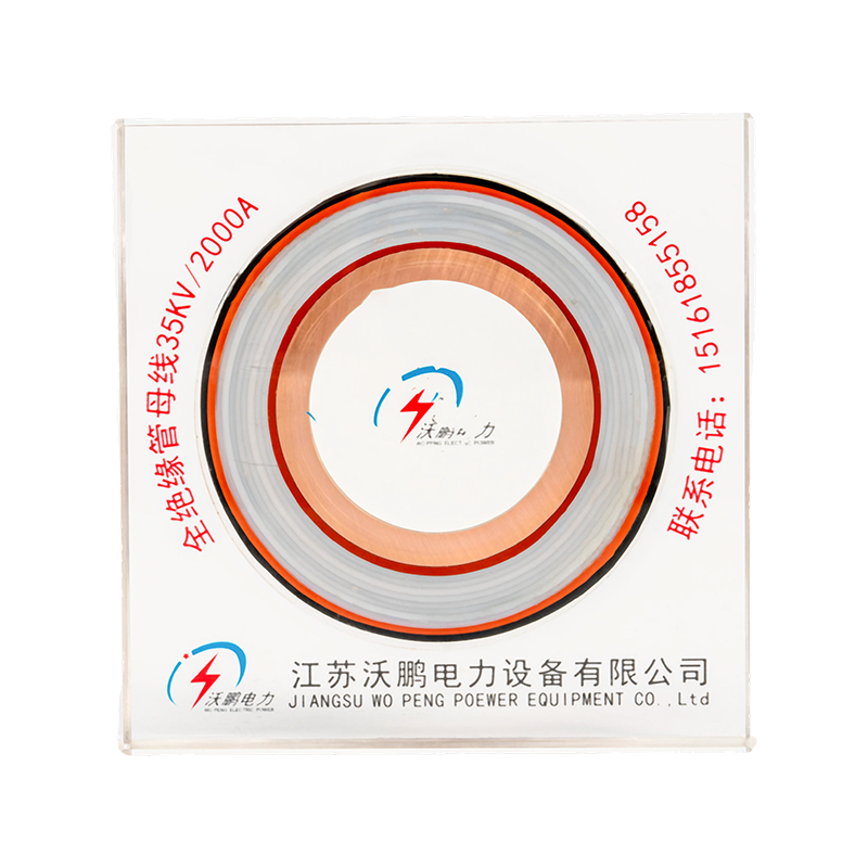
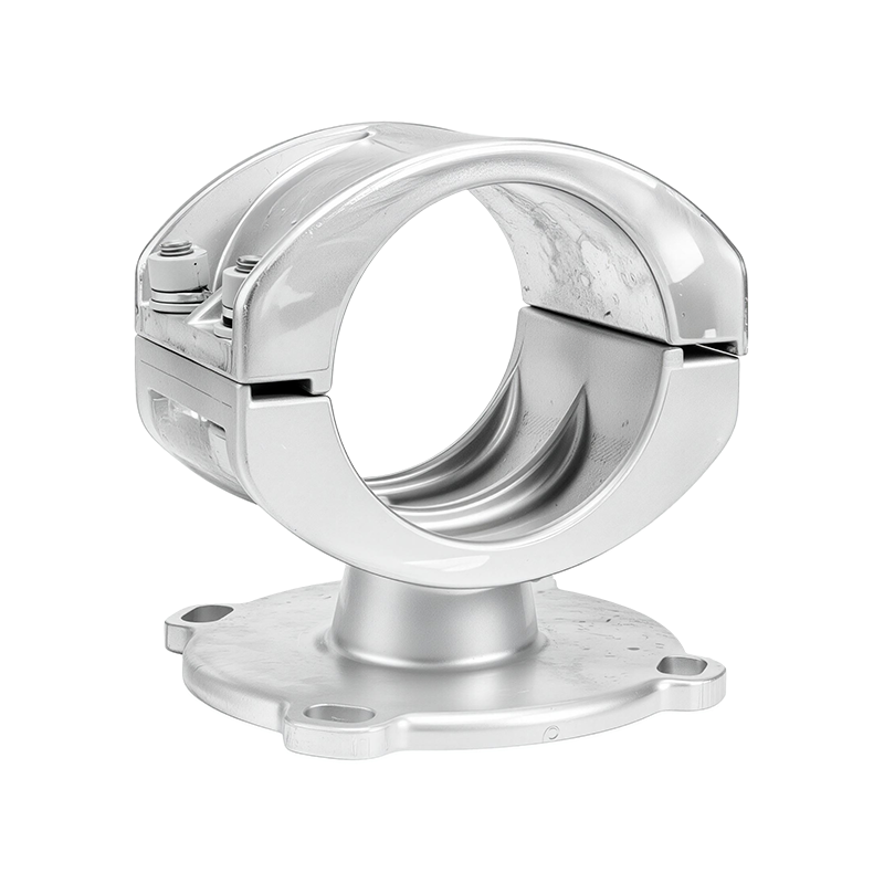
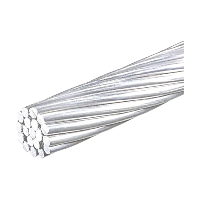
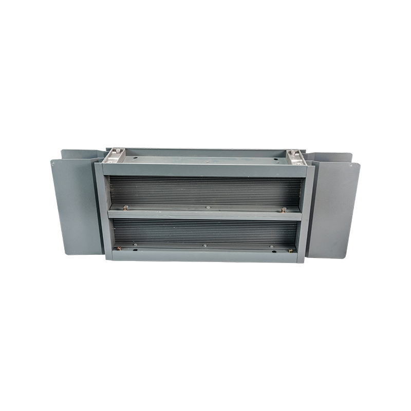
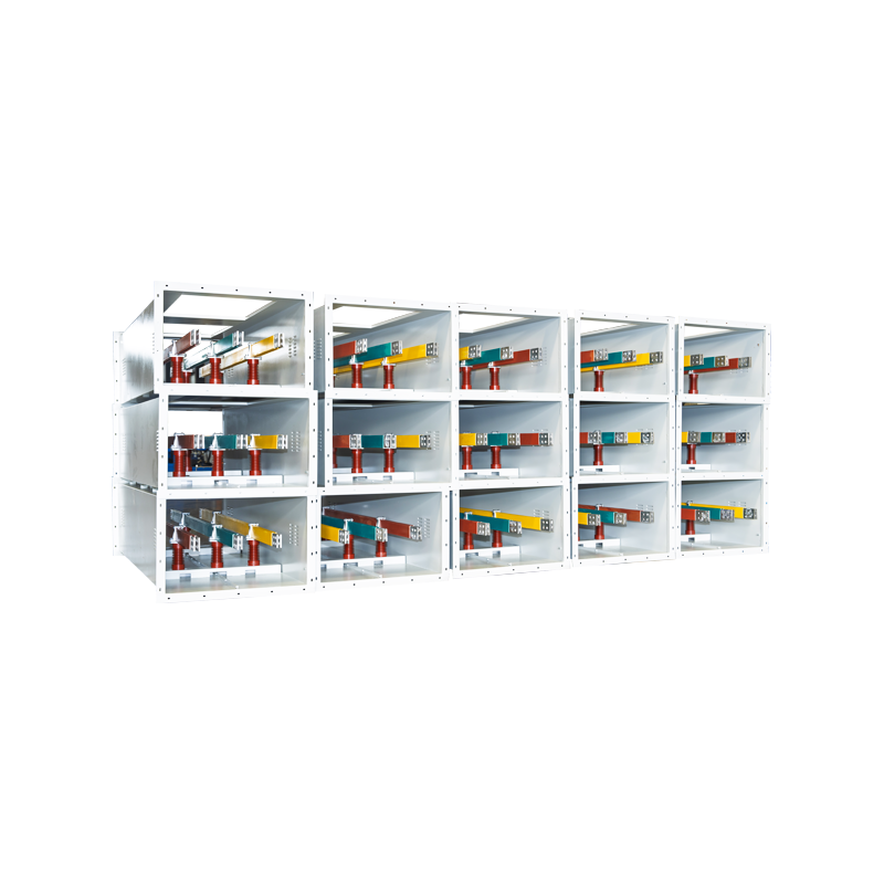
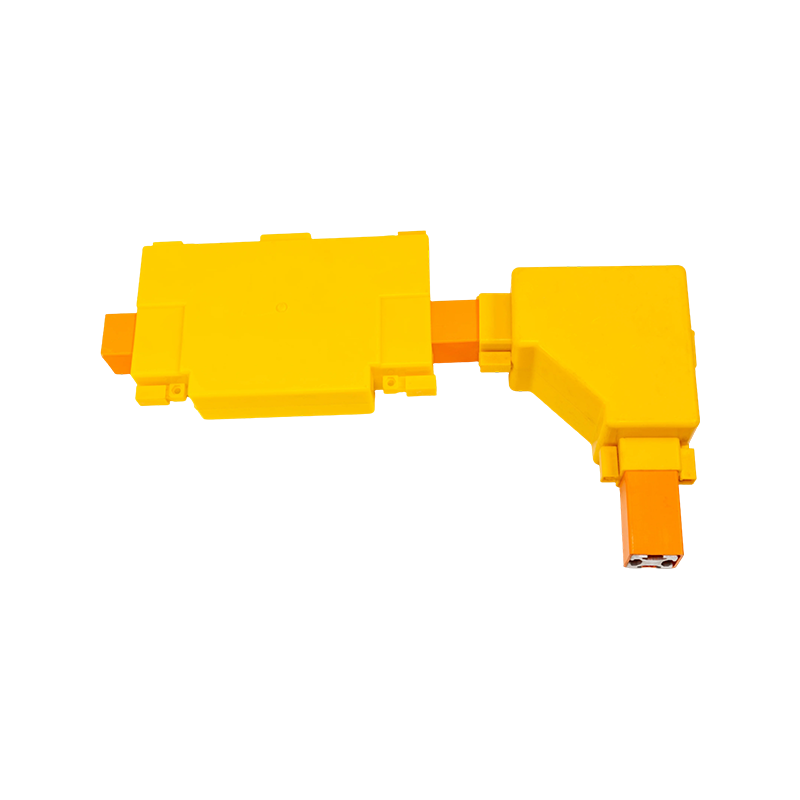

EPDM Silicone Rubber Tubular Bus Bar: Design, Performance, Manufacturing, and Applications
Content
- 1 1. What Is an EPDM Silicone Rubber Tubular Bus Bar?
- 2 2. Triple-Layer Co-Extrusion Technology
- 3 3. Electrical Performance and Electric-Field Control
- 4 4. Environmental and Mechanical Advantages
- 5 5. Joint Technology and Waterproofing
- 6 6. Advantages Over Traditional Insulated Busbars
- 7 7. Typical Applications
- 8 8. Advanced Manufacturing Strengths
- 9 9. Customization and Project Engineering
- 10 10. Installation and Maintenance Considerations
- 11 11. Frequently Asked Questions
- 11.1 Q1: What voltage range is suitable for an EPDM silicone rubber tubular bus bar?
- 11.2 Q2: What conductor materials are available?
- 11.3 Q3: What is the maximum current-carrying capacity?
- 11.4 Q4: Can the busbar be installed outdoors?
- 11.5 Q5: Can it be used in coastal or corrosive environments?
- 11.6 Q6: What is the advantage of triple-layer co-extrusion?
- 11.7 Q7: Why are stress cones used at terminals and joints?
- 11.8 Q8: Can the intermediate joint operate underwater?
- 11.9 Q9: How does it compare with ceramic-insulated busbars?
- 11.10 Q10: What information should be provided when requesting a quotation?
- 11.11 Q11: Does the manufacturer provide OEM customization?
- 11.12 Q12: What testing is performed before delivery?
- 12 12. Why Choose a Specialized Manufacturer?
- 13 13. Conclusion
- 14 References
- 15 Product: EPDM Silicone Rubber Tubular Bus Bar
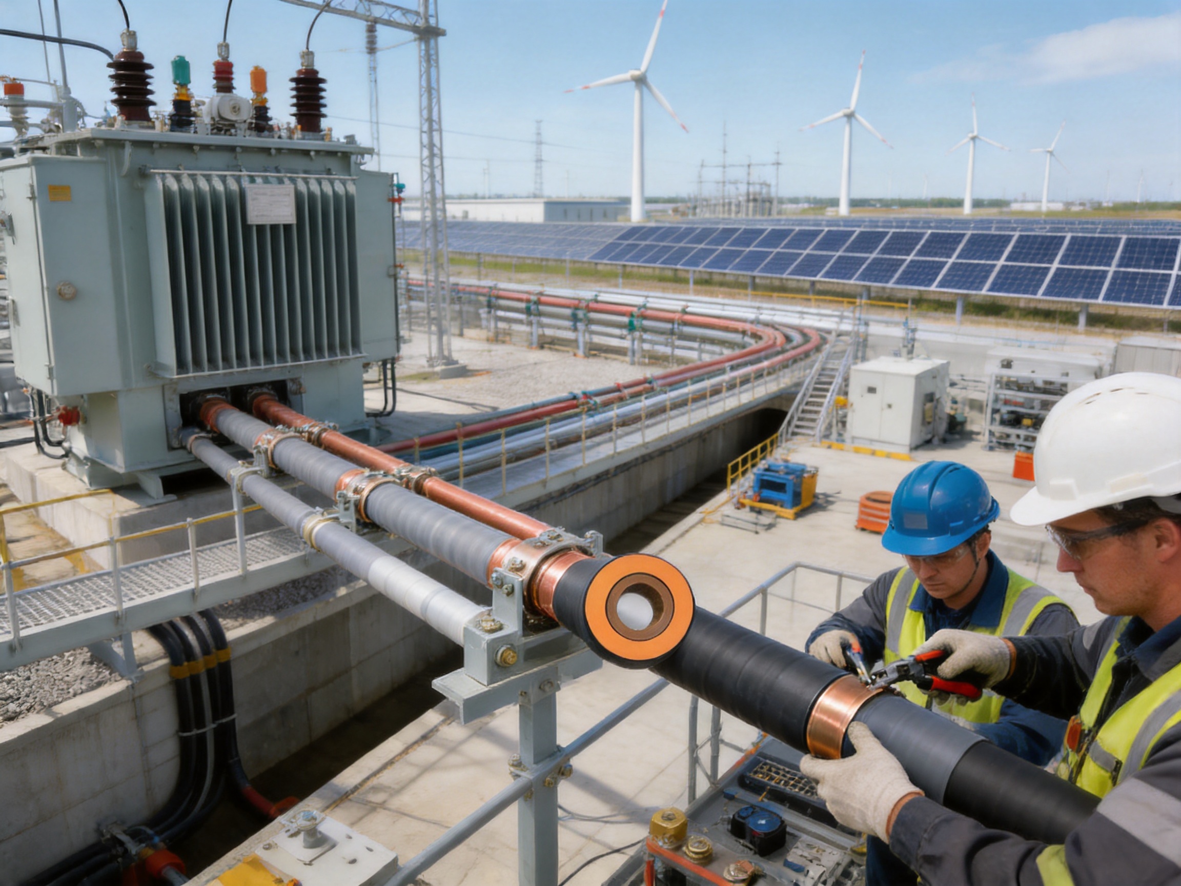
Modern power distribution systems require conductors that can carry high currents while maintaining reliable insulation, mechanical stability, and long-term environmental resistance. In substations, industrial plants, renewable energy facilities, transportation infrastructure, and large commercial buildings, the busbar system is a critical link between transformers, switchgear, circuit breakers, distribution cabinets, and other electrical equipment. Any weakness in insulation, connection quality, heat dissipation, or installation can affect the safety and continuity of the entire power system.
The EPDM silicone rubber tubular bus bar is designed to address these requirements through a composite shielded insulation structure. It combines a solid copper or aluminum tubular conductor with conductor shielding, EPDM-based insulation, insulation shielding, metallic shielding, and a protective outer sheath. These layers are produced using polymer extrusion technology, with the main insulation and shielding layers formed through a controlled triple-layer co-extrusion process.
Compared with conventional bare busbars, cable arrangements, and several traditional insulated busbar structures, the EPDM silicone rubber tubular bus bar provides a compact, fully insulated, shielded, and adaptable solution. Its design supports high-current transmission, improved electric-field control, reliable joints, waterproofing treatment, and installation in locations where conventional wiring methods are difficult.
Jiangsu Wopeng Power Technology Co., Ltd. develops and manufactures high- and low-voltage busbar systems, including insulated tubular busbars, copper and aluminum tubular busbars, epoxy resin cast tubular busbars, compact busbar systems, wind power tubular busbars, and sliding contact line systems. Supported by engineering expertise, specialized production equipment, inspection procedures, and customized OEM capabilities, the company provides busbar solutions for demanding power transmission applications.
1. What Is an EPDM Silicone Rubber Tubular Bus Bar?
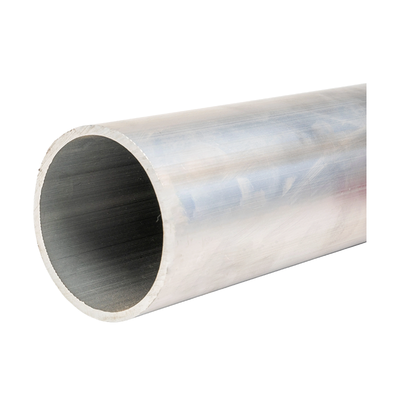
An EPDM silicone rubber tubular bus bar is an insulated tubular conductor used to transmit and distribute electrical power. Its main conductor is generally a solid copper tube, although aluminum conductors can also be selected for applications requiring reduced weight or specific project economics. Around the conductor, multiple functional layers provide electrical insulation, electric-field control, shielding, mechanical protection, and environmental resistance.
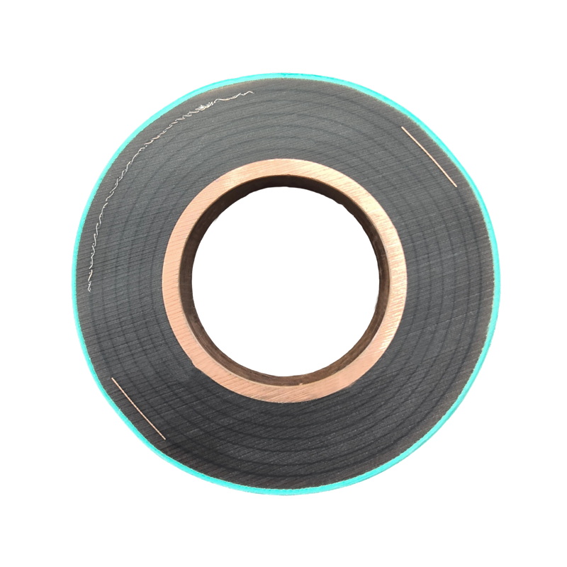
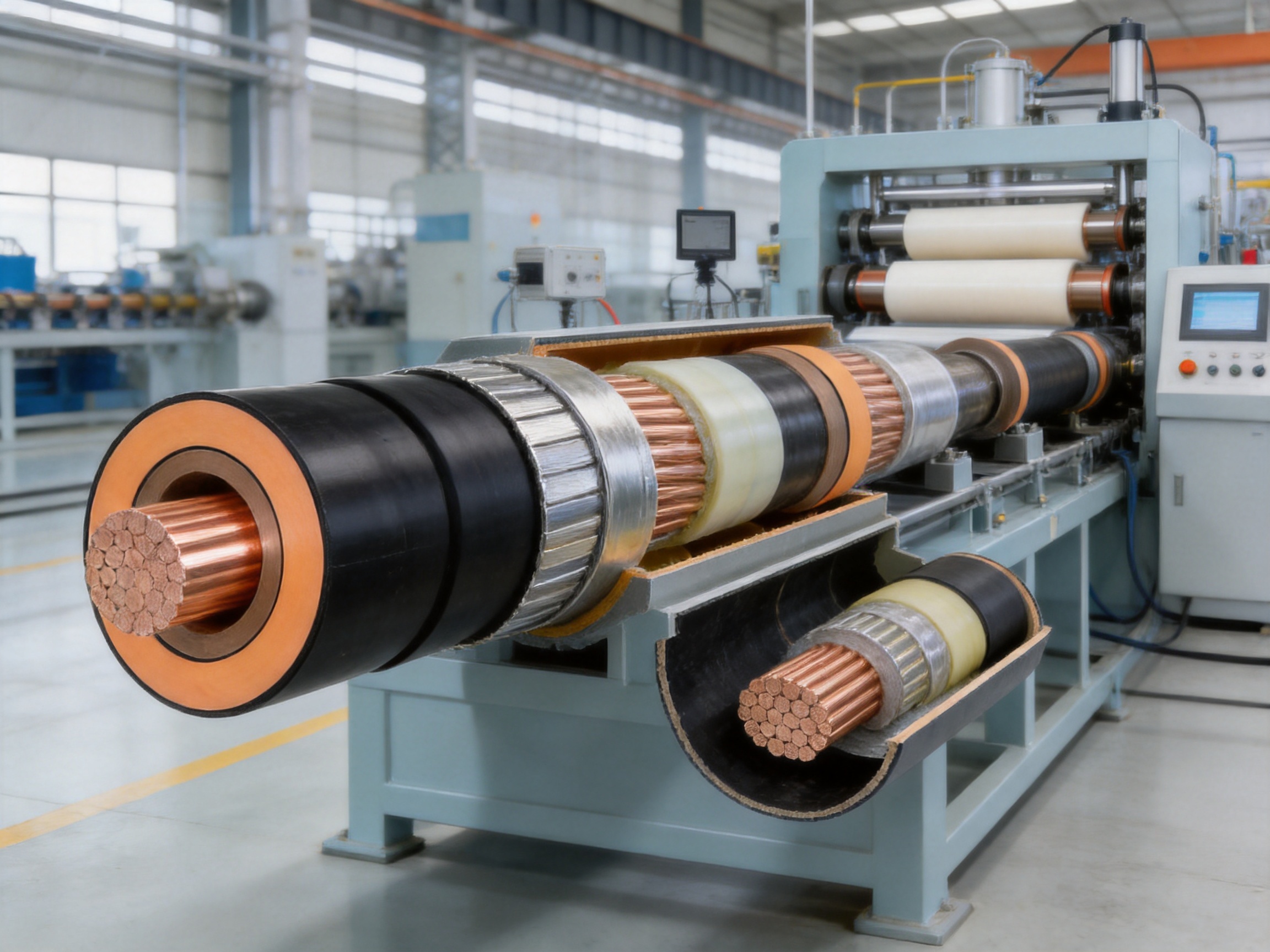
The basic structure includes a tubular conductor, a conductor shielding layer, a primary EPDM insulation layer, an insulation shielding layer, a metal shielding layer, and an outer polyolefin polymer sheath. These components are not simply assembled as separate loose materials. Instead, polymer extrusion technology is used to form closely integrated interfaces between the conductor shielding, insulation, and insulation shielding layers.
This composite structure allows the product to perform two important functions simultaneously. First, the tubular conductor carries the required electrical current. Second, the surrounding layers control the electric field and prevent direct exposure of energized conductive parts. The result is a fully insulated tubular busbar that can be installed in compact spaces and used in applications where safety, cleanliness, and reliable electrical clearances are essential.
The term “EPDM” refers to ethylene propylene diene monomer rubber. EPDM is widely used in electrical insulation and industrial sealing applications because of its resistance to ozone, ultraviolet radiation, moisture, weathering, and many chemical environments. In this busbar design, EPDM-based insulation contributes to flexibility, environmental durability, and stable operation over a broad temperature range.
Silicone rubber characteristics may also be incorporated into the insulation system or product description to emphasize flexibility and resistance to environmental aging. The precise material formulation and layer configuration are selected according to voltage level, current rating, mechanical requirements, installation conditions, and project specifications.
1.1 Main Structural Components
The conductor is the primary current-carrying element. A solid copper tube is commonly selected because copper provides high electrical conductivity, reliable mechanical strength, and good connection performance. Aluminum tubular conductors can be used where lower weight, material optimization, or project-specific requirements are important. The conductor dimensions are selected according to rated current, short-circuit withstand requirements, temperature rise limits, and installation conditions.
The conductor shielding layer creates a controlled electrical interface around the conductor. It helps reduce localized electric-field stress caused by surface irregularities and supports a more uniform distribution of electrical stress throughout the insulation system.
The primary insulation layer is based on EPDM rubber or a related elastomeric insulation formulation. This layer provides the main dielectric barrier between the energized conductor and the grounded shielding system. Its thickness and material properties are determined by the applicable voltage level and insulation coordination requirements.
The insulation shielding layer surrounds the primary insulation and helps maintain a stable electric-field distribution. It also provides a defined interface between the insulation and the metallic shielding layer. Tight contact between these layers is essential because gaps, voids, or poorly controlled interfaces can increase the risk of partial discharge and insulation deterioration.
The metallic shielding layer is generally made from copper foil or another suitable conductive shielding material. It provides electrical shielding, assists with the management of induced voltage, and can be connected to the grounding system according to the installation design.
The outer sheath is composed of a polyolefin polymer insulation material. It protects the internal layers against mechanical damage, moisture, dust, abrasion, and environmental contamination. The sheath also improves handling during installation and provides an additional barrier for the insulated busbar system.
1.2 Shielded Joints and Terminations
A fully insulated busbar system must provide continuous insulation not only along the straight busbar sections but also at terminals, bends, expansion points, and intermediate joints. For this reason, the EPDM silicone rubber tubular bus bar uses shielded joint and termination designs.
Terminal adapters provide a transition between the circular tubular conductor and the connection end of a flexible expansion joint or equipment terminal. This transition can change the conductor geometry from round to a suitable connection form while reducing abrupt changes in current density and temperature distribution.
Prefabricated cold-shrink components are used in terminal and intermediate joint structures. These components are installed without depending on high-temperature heating operations at the site. When properly prepared and positioned, they provide a consistent radial pressure and a controlled insulation interface.
Stress cones are incorporated into cold-shrink terminations to redistribute the electric field at locations where the insulation geometry changes. Cable and busbar terminations naturally contain areas of electrical stress concentration. A stress cone changes the shape of the insulation and shielding transition, reducing electric-field intensity and lowering the risk of corona discharge, partial discharge, and insulation damage.
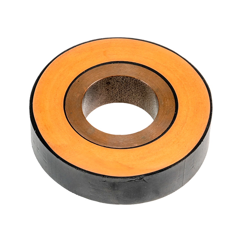
EPDM Silicone Rubber Tubular Bus Bar
2. Triple-Layer Co-Extrusion Technology
One of the most important advantages of the EPDM silicone rubber tubular bus bar is its triple-layer co-extrusion manufacturing process. In this process, the conductor shielding layer, primary insulation layer, and insulation shielding layer are extruded and formed simultaneously through a controlled production line.
Traditional multi-layer insulation systems may require separate processing steps, manual assembly, or independent application of materials. Each additional handling step can introduce variation in thickness, surface quality, concentricity, or interface contact. Triple-layer co-extrusion reduces these risks by forming the critical layers in one continuous process.
The extrusion equipment is designed to control material feeding, temperature, pressure, extrusion speed, layer thickness, and concentricity. These parameters are monitored during production so that the insulation system maintains consistent geometry along the length of the busbar.
2.1 Tight Interfaces and Reduced Voids
The interface between conductor shielding, insulation, and insulation shielding is a key factor in electrical reliability. Loose contact or microscopic gaps can create areas of nonuniform electric stress. Under high voltage, such defects may promote partial discharge, local heating, chemical degradation, or progressive insulation failure.
Co-extrusion allows the layers to be formed closely together while the polymer materials are in a controlled processing state. This helps create tight and gapless interfaces. A more uniform interface improves dielectric performance and reduces the possibility of internal defects caused by poor assembly or contamination.
The process also supports better concentricity. When the insulation thickness is more uniform around the conductor, the electric field is distributed more evenly. This is particularly important for medium- and high-voltage tubular busbars, where electrical stress must be managed across the entire insulation circumference.
2.2 Consistent Production Quality
Automated extrusion can provide greater consistency than purely manual insulation assembly. Production parameters can be recorded and adjusted, allowing engineers to identify deviations before the product leaves the line. Continuous processing also reduces the number of interruptions that could expose the insulation system to dust, moisture, or handling damage.
After extrusion, the finished busbar can be subjected to dimensional inspection, visual inspection, insulation testing, high-voltage testing, and other quality-control procedures. These inspections verify that the product meets the required electrical and mechanical specifications.
Triple-layer co-extrusion does not eliminate the need for quality control. Instead, it provides a more stable manufacturing foundation that allows inspection and testing to focus on measurable product characteristics, including insulation thickness, concentricity, surface quality, dielectric strength, and resistance to defects.
3. Electrical Performance and Electric-Field Control
In a high-voltage busbar system, insulation performance depends on more than the nominal thickness of the insulation layer. The design must control the electric field at the conductor surface, along the insulation interface, and especially at connection points where the geometry changes.
The composite shielded structure of the EPDM silicone rubber tubular bus bar is intended to create a controlled electrical environment. The conductor shielding layer smooths the electrical interface around the conductor. The main insulation layer provides dielectric separation. The insulation shield and metallic shield establish a defined outer electrical boundary.
This arrangement reduces the influence of surface irregularities and helps avoid concentrated electric-field points. When combined with prefabricated cold-shrink stress-control components, the system can manage voltage stress at terminals and joints more effectively than an unshielded arrangement.
3.1 Breakdown Strength
Product performance depends on the selected material formulation, insulation thickness, manufacturing quality, voltage class, and test method. The supplied product information identifies a representative breakdown voltage of at least 25 kV/mm for the EPDM insulation system. Actual project ratings must be confirmed through the manufacturer’s technical data, applicable standards, and project-specific testing.
A high dielectric strength allows the busbar to achieve the required insulation level without excessive external dimensions. This supports compact layouts and helps reduce the clearance requirements that would otherwise be necessary around bare or semi-insulated conductors.
3.2 Partial Discharge and Corona Control
Partial discharge is a localized electrical discharge that does not completely bridge the insulation between conductors. Although small at first, repeated discharge can gradually damage polymer insulation. Corona discharge can also occur at areas of high electric-field intensity, especially around sharp edges, abrupt geometry changes, or poorly designed terminations.
The tubular busbar design addresses these risks through smooth conductor geometry, shielded insulation layers, controlled extrusion interfaces, and stress-control components. The prefabricated cold-shrink joint changes the local geometry at voltage concentration points. This redistributes the electric field and reduces the intensity that could otherwise trigger discharge activity.
Effective discharge control depends on correct design, manufacturing cleanliness, proper installation, and testing. The joint components must be installed according to the required procedure, and conductive shielding must be connected correctly. A high-quality busbar system therefore combines material performance with disciplined production and installation practices.
3.3 Current-Carrying Capacity
The tubular conductor provides a low-resistance path for high-current transmission. A standard product configuration may support current ratings up to approximately 3000 A, while higher-capacity versions can be designed for specific projects. The final current rating depends on conductor material, cross-sectional area, ambient temperature, installation position, ventilation, enclosure conditions, duty cycle, and allowable temperature rise.
Terminal adapters help maintain current-carrying performance at the ends of the busbar. They provide a smooth transition between the round copper tube and the flexible expansion joint or equipment connection. This reduces abrupt current-density changes and helps control temperature rise near the terminals.
The design of intermediate joints is also important. Direct conductor contact can be achieved through stainless steel inner sleeves. Two semicircular connecting busbars are applied externally, and specialized stainless steel C-clamp tools are used to tighten and secure the connection. The connection is then tightened and welded according to the manufacturing and installation procedure.
This joint structure is intended to maintain electrical continuity, prevent conductor deformation, and provide sufficient mechanical stability. The joint resistance, contact pressure, weld quality, and alignment should be verified through appropriate inspections and tests.
| Characteristic | Representative Description | Project Considerations |
|---|---|---|
| Conductor | Solid copper tube or aluminum tube | Selected according to current, weight, conductivity, and mechanical requirements |
| Primary insulation | EPDM rubber-based insulation system | Thickness and formulation depend on voltage class and insulation coordination |
| Insulation structure | Conductor shield, insulation, and insulation shield formed by co-extrusion | Uniformity and interface quality are essential for high-voltage performance |
| Representative dielectric strength | At least 25 kV/mm according to supplied product information | Final values must be confirmed by technical documentation and test reports |
| Operating temperature | Approximately -40°C to 120°C in the stated product description | Actual continuous and short-time limits depend on design and application |
| Representative current capacity | Up to approximately 3000 A for standard models | Higher ratings may be customized according to conductor size and cooling conditions |
| Environmental resistance | Resistance to ozone, ultraviolet radiation, moisture, and chemical exposure | Material selection and outer sheath requirements should match the site environment |
| Joint structure | Shielded cold-shrink joints with stainless steel inner sleeves | Installation quality and grounding continuity must be verified |
4. Environmental and Mechanical Advantages
Power distribution equipment is often installed in environments that expose insulation to sunlight, rain, humidity, dust, industrial chemicals, salt, vibration, and temperature changes. The EPDM silicone rubber tubular bus bar is designed to provide stable performance under these conditions.
EPDM rubber is known for its resistance to ozone and ultraviolet radiation. This is particularly valuable in outdoor substations, renewable energy facilities, and industrial areas where insulation may be exposed to sunlight or atmospheric pollutants. Compared with some conventional PVC-based insulation systems, an EPDM-based insulation layer can offer improved resistance to outdoor aging.
The material also provides a broad operating-temperature range. The supplied information identifies an operating range of approximately -40°C to 120°C. Actual allowable temperatures depend on conductor size, current loading, thermal design, installation environment, and the requirements of the selected insulation system.
The outer polyolefin sheath protects the inner layers from physical contact and environmental contamination. It can reduce the risk of damage caused by abrasion during handling and installation. It also provides an additional barrier against moisture and dust entering the insulation system.
4.1 Outdoor Operation
Outdoor power equipment must withstand changing weather conditions throughout its service life. Rain and snow can introduce moisture, while sunlight can accelerate the aging of some polymer materials. Wind, dust, and temperature cycling can also place mechanical stress on connections and protective layers.
The EPDM silicone rubber tubular bus bar is suitable for outdoor power distribution applications when the selected design and accessories meet the local environmental requirements. Weather-resistant insulation, a protective outer sheath, shielded joints, and correct waterproofing treatment work together to support reliable service in exposed areas.
4.2 Corrosive and Industrial Environments
Metallurgical plants, chemical facilities, coastal installations, and wastewater treatment facilities may contain corrosive gases, salts, moisture, or industrial dust. These substances can reduce the service life of inadequately protected electrical equipment.
The EPDM insulation and polyolefin outer sheath provide resistance to several common environmental stresses. Nevertheless, the complete system must be evaluated rather than relying only on the insulation material. Metallic shielding, joint hardware, grounding conductors, supports, and enclosure interfaces should also be selected for the expected corrosion category.
4.3 Mechanical Flexibility and Expansion
Rigid electrical connections can experience stress when equipment moves due to thermal expansion, vibration, foundation settlement, or short-circuit forces. Flexible expansion joints can accommodate controlled movement between the tubular busbar and connected equipment.
The terminal adapter supports a gradual transition from the tubular conductor to the flexible expansion connection. This reduces mechanical concentration at the conductor end and helps maintain a stable current path. Expansion components must be designed according to the expected movement, installation geometry, and short-circuit forces.
5. Joint Technology and Waterproofing
Busbar joints are among the most important parts of a power transmission system. A straight section may have excellent insulation, but an improperly designed or installed joint can become the weakest point in the circuit. For this reason, the EPDM silicone rubber tubular bus bar uses shielded, prefabricated joint structures.
The intermediate joint has a compact arrangement that is easier to install in restricted spaces than a large conventional connection assembly. The conductor connection uses stainless steel inner sleeves to establish direct contact. Two semicircular connecting busbars are applied externally, and four stainless steel C-clamp tools are used to tighten and secure the assembly.
The joint design helps maintain the conductor’s current-carrying capacity and reduce the possibility of conductor deformation. The use of dedicated tooling improves installation repeatability and helps ensure that the connection is assembled with the required mechanical pressure.
5.1 Cold-Shrink Installation
Cold-shrink joint technology allows the insulation and stress-control components to be installed without a flame or external heating source. This can improve safety in indoor electrical rooms, industrial plants, and locations where hot work is restricted.
Cold-shrink components are prefabricated to a specific size and are expanded onto a removable support core. During installation, the support is removed so that the component contracts around the prepared busbar and connection area. The resulting pressure helps maintain close contact with the insulation and shielding surfaces.
Correct preparation remains essential. The busbar surface must be clean, dry, and free from burrs or sharp edges. Shielding layers must be positioned correctly, and the stress-control components must be installed at the specified dimensions. Installation personnel should follow the manufacturer’s instructions and use approved tools.
5.2 Short-Term Submersion Capability
After special waterproofing treatment, intermediate joints can support short-term operation while submerged in water, according to the supplied product information. This characteristic can be valuable in cable trenches, underground technical rooms, drainage-prone areas, and locations where temporary flooding is possible.
Submersion capability should not be interpreted as unlimited underwater operation. The duration, water pressure, water chemistry, joint configuration, and installation method must be evaluated for each project. The complete system should be inspected after flooding, and any damage to the outer sheath or joint sealing should be repaired promptly.
6. Advantages Over Traditional Insulated Busbars
The EPDM silicone rubber tubular bus bar offers a balanced combination of electrical performance, environmental durability, compactness, and installation flexibility. Its advantages become clearer when compared with common alternatives such as PVC-insulated busbars, ceramic-insulated busbars, bare busbars, and cable-based connections.
6.1 Compared with PVC-Insulated Busbars
PVC insulation is widely used in low-voltage electrical products because it is economical and easy to process. However, some PVC systems have limited resistance to ultraviolet radiation, elevated temperatures, and long-term outdoor exposure. The supplied comparison identifies a representative breakdown strength of no more than 15 kV/mm and a service life of approximately 10 to 15 years for a conventional PVC-insulated busbar category.
By contrast, the EPDM silicone rubber tubular bus bar is described as having a representative breakdown strength of at least 25 kV/mm, excellent UV and ozone resistance, and a potential service life of approximately 25 to 35 years under suitable operating conditions. These values are representative and must be verified for the exact product design, but they illustrate why EPDM-based insulation is attractive for outdoor and medium-voltage applications.
6.2 Compared with Ceramic Insulated Busbars
Ceramic insulation can provide high dielectric strength and good environmental resistance. However, ceramic materials are rigid and brittle. They may be vulnerable to impact, vibration, sudden mechanical stress, and difficult handling during transportation and installation.
The EPDM silicone rubber insulation system provides greater flexibility and impact tolerance than ceramic insulation. It can accommodate certain installation movements and is less likely to fracture under normal mechanical handling. Its flexibility is especially useful where busbar routes include equipment transitions, expansion joints, or restricted installation spaces.
6.3 Compared with Bare Busbars
Bare busbars require adequate phase-to-phase and phase-to-ground clearances. They may also require barriers, enclosures, supports, and careful protection against accidental contact. In dusty, humid, or contaminated environments, bare conductors can require more extensive cleaning and maintenance.
A fully insulated tubular busbar reduces the exposed energized area and helps provide a safer, cleaner arrangement. Its shielded outer surface can support compact routing and reduce the dependence on large air clearances. This can be particularly beneficial in switchgear rooms, cable mezzanines, substations, and retrofit projects where available space is limited.
6.4 Compared with Cable Connections
Power cables are flexible and widely available, but high-current cable installations may require multiple parallel cables, large cable supports, complex termination arrangements, and significant bending space. Parallel cables must be arranged carefully to control current sharing, electromagnetic effects, and heat dissipation.
A tubular busbar provides a defined conductor path with a compact cross-sectional arrangement. It can reduce the number of parallel conductors and simplify the visual layout between transformers and switchgear. The final choice depends on current, voltage, route length, flexibility, cost, installation requirements, and the need for future expansion.
7. Typical Applications
The EPDM silicone rubber tubular bus bar is suitable for medium- and high-voltage power distribution systems. The supplied product information identifies applications in the 10 kV to 35 kV range, with customized solutions possible for other voltage requirements subject to engineering evaluation and testing.
7.1 Transformer-to-Switchgear Connections
One of the most common applications is the connection between a main transformer and a low-voltage or medium-voltage switchgear cabinet. The busbar can be routed directly from the transformer terminal to the switchgear terminal.
This arrangement provides a clear and organized connection for high-current transmission. It can reduce the visual complexity associated with multiple parallel cables and may be configured as a fully insulated or semi-insulated system according to the project requirements.
7.2 Cable Trenches and Cable Mezzanines
Tubular busbars can be routed through underground cable trenches, technical corridors, or cable mezzanines. They can connect transformers to switchgear or provide connections between switchgear cabinets.
Fully insulated construction is particularly useful in locations where wiring space is limited or where the busbar must pass near building structures and other equipment. The compact design can simplify routing while maintaining electrical separation and shielding.
7.3 Industrial Plants
Industrial facilities often require reliable power connections for motors, furnaces, rolling mills, process equipment, compressors, pumps, and automated production lines. These sites may experience high current demand, vibration, dust, temperature changes, or chemical exposure.
The EPDM silicone rubber tubular bus bar can be customized for specific current ratings, route lengths, connection arrangements, and environmental conditions. Its insulated structure and compact joints are suitable for both new installations and selected retrofit projects.
7.4 Renewable Energy Facilities
Solar power stations and wind power facilities require connections between generation equipment, transformers, collection systems, and grid interconnection equipment. Outdoor exposure, temperature cycling, wind-induced vibration, and difficult maintenance access make insulation durability especially important.
Wind power tubular busbars can be designed for connection arrangements inside or near wind turbine systems. The project design must account for vibration, movement, temperature, access limitations, and the specific requirements of the turbine manufacturer.
7.5 Rail Transit and Large Commercial Facilities
Rail transit systems, airports, data centers, shopping complexes, and large public buildings require high levels of power reliability and installation organization. A compact insulated busbar can reduce the space required for high-current distribution and help separate energized conductors from surrounding equipment.
For these applications, engineering design should include fire performance, emergency power requirements, maintenance access, electromagnetic compatibility, seismic conditions, and coordination with the building’s electrical protection system.
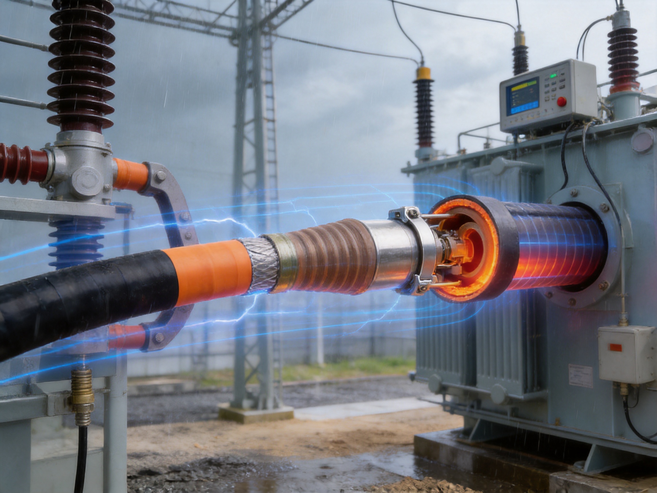
8. Advanced Manufacturing Strengths
The performance of an insulated tubular busbar depends heavily on the manufacturing process. Material selection alone cannot guarantee reliability. The conductor must be accurately formed, the insulation layers must be uniform, joints must be correctly assembled, and every finished product must be tested before shipment.
Jiangsu Wopeng Power Technology Co., Ltd. has developed production capabilities for high- and low-voltage busbar systems. Its product range includes 35 kV epoxy resin vacuum-cast tubular busbars, low-voltage epoxy-cast busway systems, copper and aluminum tubular busbars, wind power tubular busbars, compact busbar systems, and sliding contact line systems.
8.1 Engineering and Product Development
Founded in 2018, Wopeng has built a technical team that includes engineers, technical specialists, and production professionals. This structure supports product development, project customization, process improvement, and technical service.
Busbar systems are often project-specific. Conductor dimensions, route geometry, terminal types, expansion joints, support spacing, voltage levels, current ratings, and environmental requirements can vary significantly. An experienced engineering team can translate these requirements into a practical busbar design and coordinate manufacturing with site conditions.
8.2 Vacuum Casting and Extrusion-Related Capabilities
In addition to polymer extrusion technology for composite shielded busbars, Wopeng operates production lines equipped for vacuum casting, CNC machining, and automated assembly. Vacuum casting is important for epoxy resin tubular busbars because it helps reduce internal voids and improve insulation consistency.
CNC machining supports accurate production of conductor connection components, terminal adapters, flanges, support parts, and other precision items. Dimensional accuracy at the connection interface helps reduce installation difficulties and ensures correct alignment between the busbar and connected equipment.
Automated or standardized assembly processes improve repeatability. They help control component positioning, tightening procedures, joint preparation, and inspection records. For high-current electrical equipment, repeatable assembly is essential because small differences in contact pressure or alignment can influence resistance and temperature rise.
8.3 Quality Management and Testing
Each busbar system should undergo standardized inspection before delivery. Typical inspection activities include appearance checks, dimensional verification, conductor resistance measurement, insulation resistance testing, high-voltage testing, mechanical verification, and routine quality checks.
High-voltage tests confirm the ability of the insulation system to withstand specified electrical stress. Insulation tests evaluate the condition of the dielectric layers. Mechanical verification ensures that conductors, joints, supports, and connection components meet the required structural conditions.
Testing collaboration with third-party institutions provides an additional level of independent validation. Independent testing may be required by customers, project owners, certification bodies, or national and international standards. It can also help verify performance claims for specialized or customized busbar designs.
8.4 Manufacturing Traceability
A professional busbar manufacturer should maintain traceability for conductor materials, insulation compounds, extrusion parameters, joint components, inspection records, and final test results. Traceability supports quality investigation and allows the manufacturer to identify the production conditions associated with a specific product.
Wopeng’s manufacturing and inspection approach is intended to support consistent delivery for power generation, substations, wind energy, industrial manufacturing, rail transit, and large commercial facilities. Its products operate across more than 17 provinces and multiple industrial sectors, reflecting experience with varied site conditions and electrical system requirements.
9. Customization and Project Engineering
There is no single tubular busbar specification suitable for every project. A reliable supplier should be able to customize the busbar according to voltage, current, conductor material, route geometry, installation environment, and connection requirements.
9.1 Voltage and Insulation Selection
The rated voltage determines the insulation thickness, shielding configuration, terminal design, clearance coordination, and test requirements. Medium-voltage systems such as 10 kV, 20 kV, and 35 kV may require different insulation structures and accessories.
Customers should provide the nominal system voltage, maximum operating voltage, lightning impulse withstand requirements, power-frequency withstand requirements, grounding arrangement, and applicable standards. This information allows the manufacturer to select an appropriate insulation and shielding system.
9.2 Current and Thermal Design
The conductor cross-section must be selected according to continuous current, overload conditions, short-circuit current, duration of short circuit, ambient temperature, installation position, and heat dissipation. Copper and aluminum conductors have different conductivity, weight, thermal behavior, and connection requirements.
Thermal calculations should include terminal connections and intermediate joints. A busbar that has adequate conductor capacity but poorly designed terminals may still experience excessive local temperature rise. The use of terminal adapters and flexible expansion joints helps address this transition area.
9.3 Route Geometry and Connection Points
Project drawings should identify the distance between connected equipment, elevation differences, bends, support locations, expansion requirements, phase arrangement, and available installation space. The manufacturer can then prepare a detailed busbar layout and determine the number and type of straight sections, bends, terminals, joints, and flexible connections.
Accurate site measurements are especially important for retrofit projects. Errors in equipment centerlines or connection elevations can make installation difficult and may place mechanical stress on the busbar. Factory prefabrication is most effective when the project dimensions are carefully verified.
9.4 Environmental Requirements
The site assessment should include indoor or outdoor installation, altitude, ambient temperature, humidity, flooding risk, ultraviolet exposure, salt contamination, chemical exposure, dust, vibration, seismic requirements, and fire-protection requirements.
For coastal or chemically corrosive environments, the metallic shielding, hardware, supports, and grounding connections should be reviewed together with the EPDM insulation and outer sheath. Waterproofing requirements should be specified for cable trenches, underground rooms, and other locations where temporary water exposure may occur.
10. Installation and Maintenance Considerations
Proper installation is essential to obtain the expected performance of a fully insulated tubular busbar. The product should be transported, stored, handled, and installed according to the manufacturer’s instructions.
10.1 Storage and Handling
Busbar sections and joint kits should be stored in a clean, dry, and protected area. The ends should remain sealed or protected from dust and moisture. Heavy components should be lifted using approved lifting points, and the outer sheath should not be dragged across rough surfaces.
Before installation, each section should be inspected for dents, scratches, cracks, contamination, or damage to protective packaging. Any abnormality should be recorded and reported before the section is connected to the electrical system.
10.2 Joint Preparation
Joint preparation should be carried out by trained personnel. The conductor surface must be clean and properly prepared. Sharp edges and burrs should be removed without damaging the conductor. Shielding layers must be cut and positioned according to the specified dimensions.
Stainless steel inner sleeves, semicircular connecting busbars, C-clamps, stress-control components, and sealing parts should be checked before assembly. The correct tools and tightening procedures must be used to achieve the specified contact pressure and mechanical stability.
10.3 Grounding and Shield Continuity
The metallic shielding system must be connected to the grounding network according to the electrical design. Shield continuity should be verified at joints and terminations. Grounding conductors must be appropriately sized and protected against mechanical and environmental damage.
Incorrect or incomplete shield grounding can affect electric-field control and may create unsafe touch-voltage conditions. Grounding design should therefore be coordinated with the substation or facility grounding system.
10.4 Testing Before Energization
Before energization, the completed busbar system should undergo the tests required by the project specification and applicable standards. These may include insulation resistance testing, power-frequency withstand testing, partial-discharge testing, conductor continuity testing, shield continuity testing, phase identification, and visual inspection.
Test results should be documented and retained as part of the project quality file. If the busbar has been exposed to water, excessive mechanical stress, or contamination during installation, additional inspection and testing may be appropriate.
10.5 Routine Maintenance
Fully insulated tubular busbars generally require less routine cleaning than bare busbars, but they should not be ignored after commissioning. Maintenance personnel should inspect the outer sheath, supports, grounding connections, terminal areas, expansion joints, and accessible joint covers.
Thermal imaging can help identify abnormal temperature rise at terminals and joints. Visual inspection can detect discoloration, cracking, deformation, loose supports, or signs of water ingress. Maintenance intervals should be determined according to the operating environment, system criticality, manufacturer recommendations, and local regulations.
11. Frequently Asked Questions
Q1: What voltage range is suitable for an EPDM silicone rubber tubular bus bar?
The supplied product information identifies the main application range as 10 kV to 35 kV medium- and high-voltage systems. Customized designs may be possible for other voltage levels, but the insulation structure, shielding arrangement, terminal system, and test requirements must be reviewed by the manufacturer for each project.
Q2: What conductor materials are available?
Solid copper tubular conductors are commonly used because of their high conductivity and strong connection performance. Aluminum tubular conductors can also be selected where lower weight or project-specific material requirements are important. The final choice should consider current rating, voltage level, weight, mechanical strength, thermal performance, connection technology, and budget.
Q3: What is the maximum current-carrying capacity?
Standard models can carry up to approximately 3000 A according to the supplied product description. Higher-capacity versions may be customized. The actual rating depends on conductor size, material, ambient conditions, installation arrangement, allowable temperature rise, and the design of terminals and joints.
Q4: Can the busbar be installed outdoors?
Yes. The EPDM-based insulation and protective outer sheath provide resistance to ultraviolet radiation, ozone, moisture, and weathering. Outdoor designs must still account for temperature, solar exposure, pollution, wind, mechanical supports, drainage, and the corrosion protection of metallic components.
Q5: Can it be used in coastal or corrosive environments?
It can be suitable for coastal and industrial environments because EPDM-based insulation has strong resistance to weathering and several chemical stresses. However, the complete busbar system must be evaluated. Metallic shielding, joint hardware, grounding connections, supports, and enclosures should be selected for the site’s corrosion conditions.
Q6: What is the advantage of triple-layer co-extrusion?
Triple-layer co-extrusion forms the conductor shielding, primary insulation, and insulation shielding in one controlled process. It helps create tight interfaces, reduce gaps, improve concentricity, and maintain consistent layer thickness. These characteristics support electric-field control and reduce the risk of insulation defects.
Q7: Why are stress cones used at terminals and joints?
Stress cones modify the geometry at voltage concentration points. This redistributes the electric field and reduces local electric-field intensity. As a result, the design aims to reduce corona discharge, partial discharge, insulation damage, and the probability of premature breakdown.
Q8: Can the intermediate joint operate underwater?
After special waterproofing treatment, the intermediate joint can support short-term submerged operation according to the supplied information. It is not intended to represent unlimited underwater service. The duration and conditions of submersion should be confirmed for the project, and the system should be inspected after flooding.
Q9: How does it compare with ceramic-insulated busbars?
Ceramic insulation can offer high dielectric strength but is rigid and relatively brittle. EPDM silicone rubber insulation provides greater flexibility and impact tolerance while maintaining strong insulation performance. The best selection depends on voltage, environment, mechanical conditions, installation method, and lifecycle requirements.
Q10: What information should be provided when requesting a quotation?
Customers should provide system voltage, rated current, short-circuit level, conductor material preference, route length, equipment connection dimensions, elevation differences, indoor or outdoor conditions, ambient temperature, altitude, environmental contamination, waterproofing requirements, applicable standards, and required delivery schedule. Site drawings and photographs are also helpful for accurate engineering.
Q11: Does the manufacturer provide OEM customization?
Jiangsu Wopeng Power Technology Co., Ltd. provides customized busbar solutions for project-specific voltage, current, structure, route, and connection requirements. Its engineering and production teams can coordinate conductor selection, insulation design, terminals, joints, supports, testing, and documentation.
Q12: What testing is performed before delivery?
Testing may include dimensional inspection, appearance inspection, insulation resistance testing, high-voltage testing, conductor continuity testing, mechanical verification, and routine quality checks. The exact test program depends on the product type, voltage level, customer specification, and applicable standards. Third-party testing can also be coordinated when required.
12. Why Choose a Specialized Manufacturer?
A tubular busbar is not simply a metal conductor covered with an insulating material. It is an engineered electrical system that includes conductor design, insulation coordination, electric-field control, joint technology, thermal performance, grounding, mechanical support, and installation procedures.
A specialized manufacturer can evaluate these elements together. This reduces the risk that a component will be selected in isolation without considering its effect on the complete system. It also allows the customer to receive coordinated drawings, technical specifications, inspection documents, installation instructions, and test records.
Jiangsu Wopeng Power Technology Co., Ltd. focuses on high- and low-voltage busbar systems and supports applications across power generation, substations, wind energy, industrial manufacturing, rail transit, and commercial facilities. Its product portfolio and production equipment allow it to address both standard and customized requirements.
The company operates modern production lines equipped with vacuum casting systems, CNC machining equipment, and automated assembly technologies. Its technical personnel support product design and manufacturing, while quality-control procedures help ensure that products meet demanding operating requirements.
For customers seeking a China OEM supplier, factory-direct production can support customized dimensions, connection configurations, insulation structures, packaging, documentation, and project quantities. Technical discussions before production are important to confirm electrical ratings, site conditions, interface dimensions, delivery requirements, and testing expectations.
13. Conclusion
The EPDM silicone rubber tubular bus bar is a compact, shielded, and fully insulated solution for high-current power transmission and distribution. Its combination of a solid copper or aluminum tubular conductor, EPDM-based insulation, metallic shielding, polyolefin outer protection, prefabricated cold-shrink joints, and stress-control components addresses the principal challenges of medium- and high-voltage busbar applications.
Triple-layer co-extrusion technology provides tight interfaces between the conductor shielding, insulation, and insulation shielding. This supports uniform electric-field distribution, reliable insulation performance, and consistent production quality. The shielded joint system provides compact installation, controlled electrical stress, reliable conductor connections, and short-term water-resistance capability after appropriate waterproofing treatment.
Compared with PVC-insulated products, the EPDM system offers stronger resistance to ultraviolet radiation, ozone, and outdoor aging. Compared with ceramic insulation, it provides greater flexibility and mechanical tolerance. Compared with bare busbars and complex parallel-cable arrangements, it offers a cleaner and more compact insulated connection for high-current installations.
The final performance of any busbar system depends on correct engineering, material selection, manufacturing, installation, testing, and maintenance. By combining advanced extrusion and casting technologies with CNC machining, standardized assembly, inspection procedures, and project customization, Jiangsu Wopeng Power Technology Co., Ltd. provides integrated busbar solutions for demanding electrical infrastructure.
For technical consultation and customized project requirements, customers may contact Jiangsu Wopeng Power Technology Co., Ltd. at +86-180 3625 3000 or admin@wpbusbar.com. The company is located at No. 8, Yanjin Road, Chengxi Industrial Park, Shanyang Town, Baoying County, Yangzhou City, Jiangsu Province, China.
References
1. IEC 62271 series, High-Voltage Switchgear and Controlgear.
2. IEC 60502 series, Power Cables with Extruded Insulation and Their Accessories.
3. IEC 60840, Power Cables with Extruded Insulation and Their Accessories for Rated Voltages Above 30 kV up to 150 kV.
4. IEC 61439 series, Low-Voltage Switchgear and Controlgear Assemblies.
5. IEC 60270, High-Voltage Test Techniques—Partial Discharge Measurements.
6. IEC 60071 series, Insulation Coordination.
7. ASTM D1418, Standard Practice for Rubber and Rubber Latices—Nomenclature.
8. ASTM D573, Standard Test Method for Rubber—Deterioration in an Air Oven.
9. Manufacturer-supplied technical information for EPDM silicone rubber tubular busbar systems.
10. Manufacturer-supplied information regarding triple-layer co-extrusion, shielded joints, terminal adapters, and cold-shrink stress-control components.
Product: EPDM Silicone Rubber Tubular Bus Bar



-
 +86-180 3625 3000
-
 admin@wpbusbar.com
-
 No. 8, Yanjin Road, Chengxi Industrial Park, Shanyang Town, Baoying County, Yangzhou City, Jiangsu Province, China
Copyright © Jiangsu Wopeng Power Technology Co., Ltd.
All Rights Reserved.
 Custom Insulated Bus Bar Manufacturer
Tubular Busbar System Factory
Custom Insulated Bus Bar Manufacturer
Tubular Busbar System Factory