

 EN
EN

 English
 русский
 Français
 Español
 عربى
عربى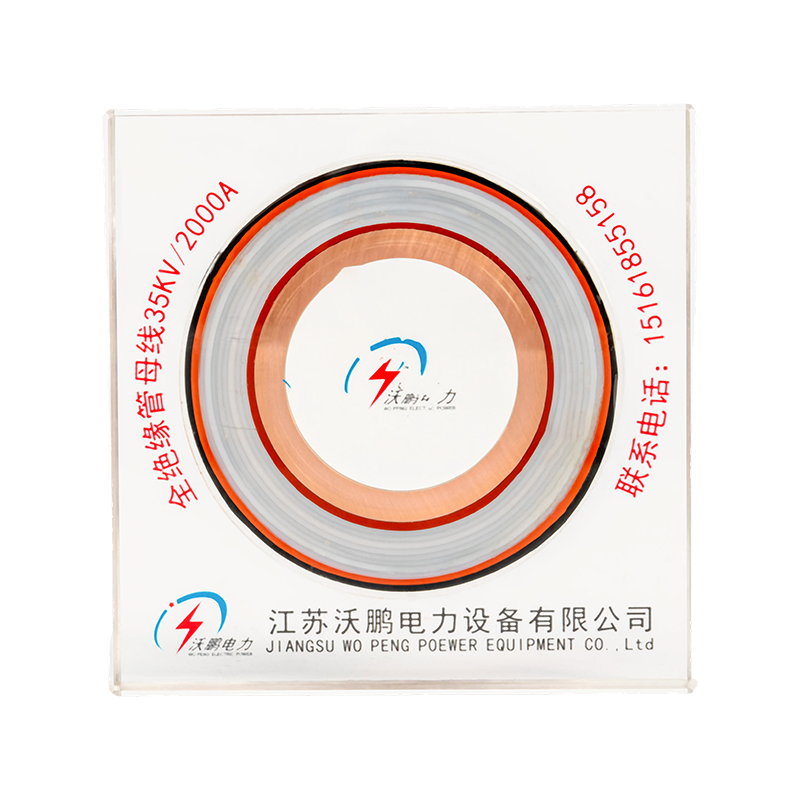
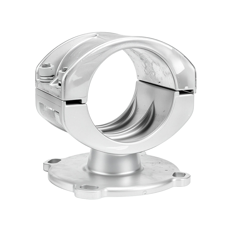
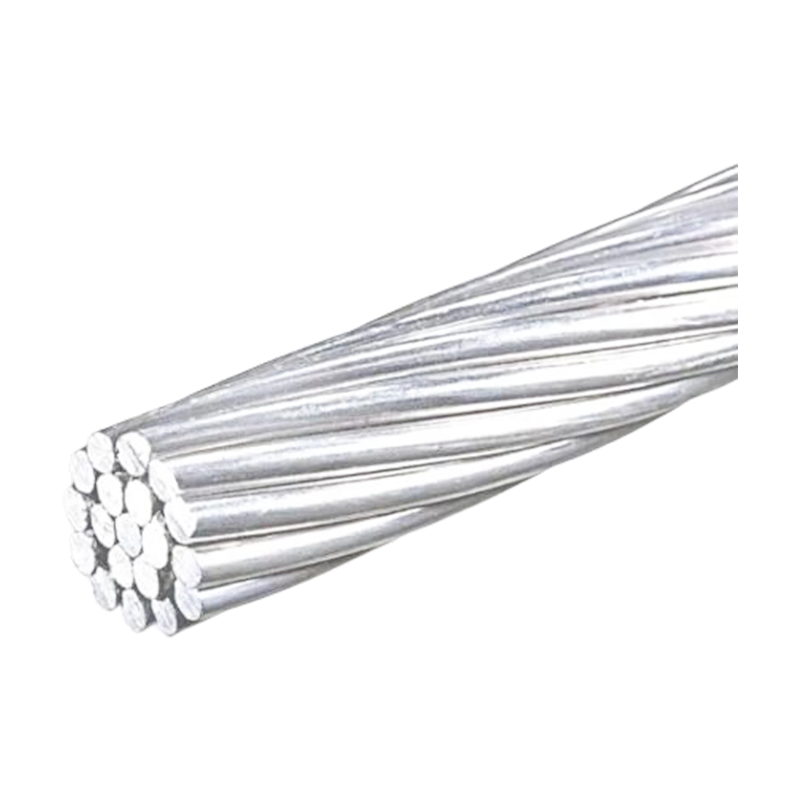
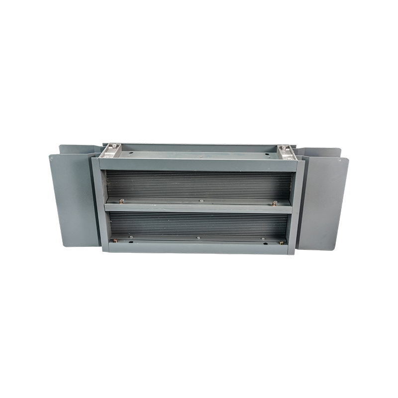
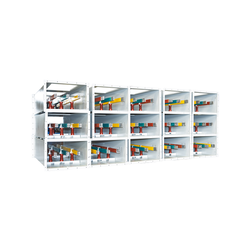
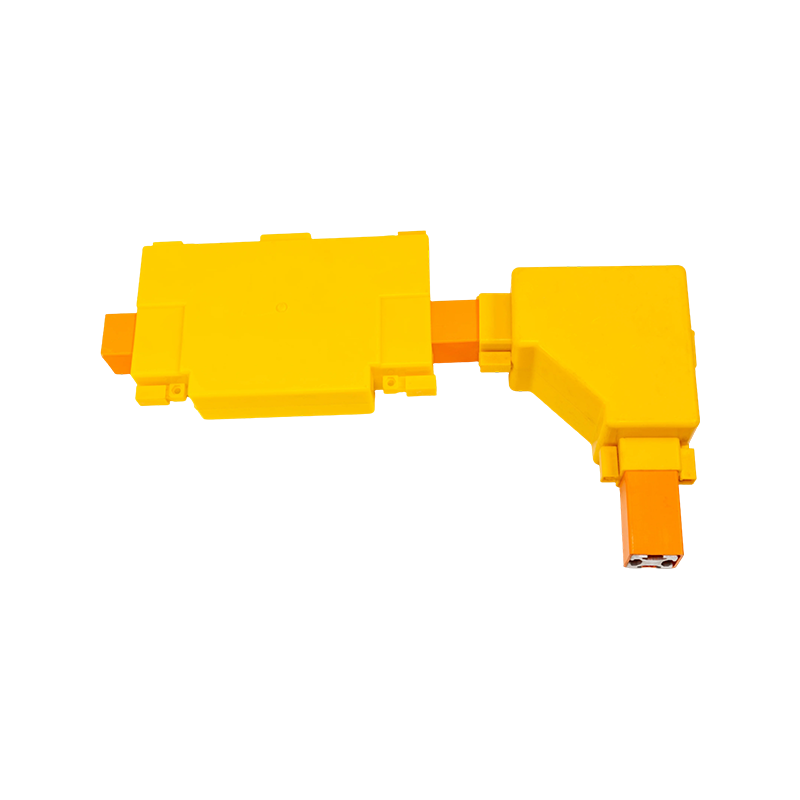

EPDM Silicone Rubber Tubular Bus Bar: Advanced Insulated Power Transmission for Medium- and High-Voltage Systems
Content
- 1 1. Product Definition and Operating Purpose
- 2 2. Composite Shielded Insulation Structure
- 3 3. Triple-Layer Co-Extrusion Manufacturing Technology
- 4 4. Electric-Field Management and Insulation Reliability
- 5 5. Shielded Intermediate Joint Technology
- 6 6. Main Advantages over Conventional Busbar and Cable Solutions
- 7 7. Typical Applications
- 8 8. Application Configuration Options
- 9 9. Manufacturing Strengths and Quality Management
- 10 10. Customization Process for OEM Projects
- 11 11. Installation and Commissioning Considerations
- 12 12. Maintenance and Service-Life Management
- 13 13. Selection Guide for Project Engineers
- 14 14. Frequently Asked Questions
- 14.1 Q1: What is an EPDM silicone rubber tubular bus bar used for?
- 14.2 Q2: What voltage range is suitable for this product?
- 14.3 Q3: Is the conductor made from copper or aluminum?
- 14.4 Q4: What is the main advantage of triple-layer co-extrusion?
- 14.5 Q5: Why are stress cones used at terminals?
- 14.6 Q6: Can the busbar be installed outdoors?
- 14.7 Q7: Can it be used in coastal or chemical environments?
- 14.8 Q8: Can intermediate joints withstand water exposure?
- 14.9 Q9: What is the maximum current-carrying capacity?
- 14.10 Q10: What information is needed for a quotation?
- 14.11 Q11: How does this product compare with conventional cables?
- 14.12 Q12: Does fully insulated construction eliminate the need for grounding?
- 15 15. Why Choose a Specialized Manufacturer
- 16 16. Conclusion
- 17 References
- 18 Product: EPDM Silicone Rubber Tubular Bus Bar
Reliable power transmission is essential wherever electricity must move safely, efficiently, and continuously between transformers, switchgear, distribution cabinets, generators, and other high-current equipment. Traditional cable and busbar arrangements can become difficult to install when current levels are high, available space is limited, or the operating environment includes moisture, ultraviolet radiation, chemicals, dust, vibration, and temperature changes. The EPDM silicone rubber tubular bus bar provides an engineered alternative by combining a tubular copper or aluminum conductor with a fully insulated, shielded, and compact construction.
This product is designed for medium- and high-voltage applications where electrical insulation, current-carrying performance, mechanical strength, and environmental resistance must work together. Its composite shielded insulation structure integrates the conductor, conductor shielding, primary insulation, insulation shielding, metal shielding, and outer sheath into a coordinated system. Through triple-layer co-extrusion technology, the insulation and shielding layers are formed with tight interfaces and minimal risk of voids or separation.
Unlike an exposed rigid busbar, the fully insulated tubular bus bar can be installed in locations where phase-to-phase clearance and phase-to-ground clearance are difficult to maintain. Unlike many conventional cable arrangements, its tubular conductor provides a defined mechanical path and efficient heat dissipation. Its prefabricated cold-shrink terminals and shielded intermediate joints further support safe installation, controlled electric-field distribution, and long-term operating stability.
For customers seeking customized insulated bus bar systems, Jiangsu Wopeng Power Technology Co., Ltd. combines product engineering, modern manufacturing equipment, testing capabilities, and application experience. The company supplies busbar solutions for substations, wind power, industrial facilities, rail transit, power generation, and large commercial infrastructure. Its portfolio covers low-voltage systems through 35kV applications, including copper and aluminum tubular busbars, epoxy resin vacuum-cast tube busbars, compact busbar systems, and sliding contact line systems.
1. Product Definition and Operating Purpose
An EPDM silicone rubber tubular bus bar is a high-current electrical conductor enclosed within a composite insulated and shielded tubular structure. The conductor may be manufactured from copper or aluminum, depending on the required conductivity, current rating, weight, cost, and installation conditions. The insulation system uses EPDM-based rubber material, while the shielding system controls the electric field around the conductor and supports a fully insulated line configuration.
The product is primarily intended for medium- and high-voltage power transmission over relatively short or moderate distances inside substations, industrial plants, renewable energy facilities, power stations, and distribution installations. It can connect a transformer to a switchgear cabinet, connect multiple switch cabinets, route through a cable trench, or pass through a cable mezzanine where conventional installation methods would be difficult.
The tubular form provides a continuous and orderly connection between electrical equipment. It can be manufactured according to the required route, phase arrangement, terminal position, conductor size, voltage class, and installation space. This makes it suitable for projects where standard cable lengths or prefabricated rigid busduct dimensions cannot provide an efficient solution.
The term “fully insulated” refers to the fact that the energized conductor is covered by a complete insulation and shielding system along the line, including the joint and terminal areas when the complete system is correctly installed. This design reduces the exposure of live parts, helps protect personnel, minimizes the risk of accidental contact, and allows more compact routing than an uninsulated busbar installation.
1.1 Typical Voltage and Current Range
The product is mainly applied in medium- and high-voltage systems from approximately 10kV to 35kV, with customized engineering available for other voltage requirements. Standard product configurations can support high current levels, with representative models reaching up to 3000A. The final current rating depends on conductor material, conductor cross-sectional area, operating temperature, installation method, ambient conditions, short-circuit requirements, and applicable standards.
Voltage and current selection should be completed through a technical review rather than by selecting a nominal size alone. Engineers normally evaluate continuous current, short-time withstand current, peak withstand current, system frequency, insulation coordination, altitude, ambient temperature, route length, bend radius, terminal geometry, and the expected environmental conditions.
2. Composite Shielded Insulation Structure
The EPDM silicone rubber tubular bus bar uses several coordinated layers. Each layer performs a specific electrical, mechanical, or environmental function. The combined structure is more important than any individual material because medium- and high-voltage performance depends on the continuity and compatibility of the conductor, insulation, shielding, joints, and terminals.
2.1 Tubular Conductor
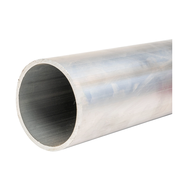
The central conductor is a solid copper tube or aluminum tube. Copper offers high electrical conductivity, strong connection performance, and excellent resistance to thermal stress. Aluminum provides a lower-weight alternative and can be advantageous where long routes, lifting restrictions, or material cost are important. The conductor is manufactured to controlled dimensions so that it can connect accurately with terminal adapters and intermediate joint components.
A tubular conductor can provide a favorable relationship between current-carrying capacity, mechanical stiffness, and weight. Its geometry also creates a stable route between connected equipment. Depending on the design, the conductor can be prepared for direct connection to terminals, expansion joints, and intermediate sleeves.
2.2 Conductor Shielding Layer
The conductor shielding layer surrounds the metal conductor and provides a controlled interface between the conductor and the primary insulation. This semiconductive layer helps smooth local electrical stress and reduces the possibility that irregularities on the conductor surface will create concentrated electric fields.
In a high-voltage insulation system, the conductor surface must be treated as part of the electric-field design. Small geometric irregularities, contamination, or gaps can increase local field intensity. A continuous conductor shield helps create a more uniform transition from the energized metal surface to the main insulation layer.
2.3 EPDM Primary Insulation
The principal insulation layer is ethylene propylene diene monomer rubber, commonly known as EPDM. The material provides electrical insulation while also offering flexibility, weather resistance, and resistance to ozone and ultraviolet exposure. The supplied product information indicates a typical insulation thickness range of approximately 3mm to 8mm, although the final design is determined by voltage level and technical requirements.
EPDM insulation is suitable for demanding industrial and outdoor conditions because it can remain functional across a broad temperature range. A representative working temperature range is approximately -40°C to 120°C, subject to the exact material formulation, installation conditions, and applicable product standard. Properly selected EPDM compounds can resist moisture, ozone, ultraviolet radiation, and many common environmental contaminants.
2.4 Insulation Shielding and Metal Shielding
The insulation shield provides a controlled outer electrical boundary around the primary insulation. It supports electric-field stability and helps maintain predictable voltage stress throughout the insulated section. A metal shielding layer, made from copper foil in the described construction, can provide additional shielding and grounding continuity when incorporated into the system design.
The shielding system is especially important at joints and terminals. A discontinuity in the shield can create an electrical stress concentration or compromise the fully insulated concept. For this reason, the product uses shielded joint technology so that the shielding function extends through the complete line rather than stopping at the main tubular section.
2.5 Outer Sheath
The outer sheath is made from a polyolefin polymer insulation material. It protects the internal layers from mechanical abrasion, moisture, dirt, and environmental exposure. The sheath also provides an additional barrier during handling and installation. Its surface can be selected or configured according to the required operating environment and installation arrangement.
A well-designed outer sheath must remain compatible with the EPDM insulation and shielding layers while maintaining flexibility or rigidity appropriate to the installation. It should also resist cracking, peeling, and excessive aging during the expected service life.
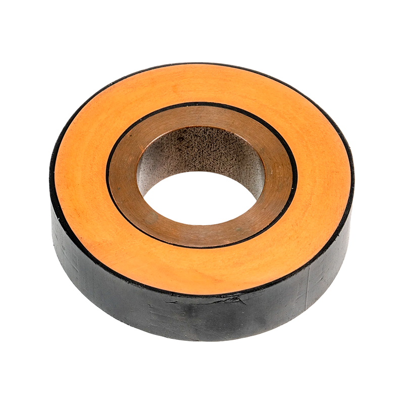
EPDM Silicone Rubber Tubular Bus Bar
3. Triple-Layer Co-Extrusion Manufacturing Technology
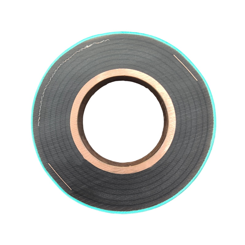
One of the main technical advantages of this tubular bus bar is triple-layer co-extrusion. The conductor shielding, primary insulation, and insulation shielding are extruded and formed simultaneously in a controlled production process. This approach is different from assembling separate insulation components around a conductor after individual manufacturing steps.
Co-extrusion helps create tight and gapless interfaces between the internal shield, insulation layer, and external shield. The reduction of gaps is important because voids can become locations for partial discharge, electrical treeing, moisture accumulation, or mechanical separation. By forming the layers in one coordinated process, the manufacturer can improve dimensional consistency and reduce interface-related defects.
3.1 Control of Material Interfaces
Electrical insulation performance depends strongly on the quality of material interfaces. The interface between the conductor shield and EPDM insulation must be smooth and continuous. The interface between the insulation and insulation shield must also remain tightly bonded or closely integrated. Any unexpected air gap can create a dielectric discontinuity because air has a lower dielectric strength than the surrounding solid insulation.
Triple-layer co-extrusion controls the relative position, thickness, temperature, pressure, and extrusion speed of multiple layers during production. Process parameters are monitored so that the layers remain concentric and stable. This improves the uniformity of the finished insulation system and supports reliable performance under operating voltage and thermal cycling.
3.2 Dimensional and Process Stability
Modern extrusion lines can control conductor alignment, insulation thickness, shielding thickness, outer diameter, and surface quality. These variables influence the electrical field, bending behavior, terminal fit, joint assembly, and final installation accuracy. Stable production reduces variation between product sections and makes field assembly more predictable.
Manufacturing controls may include incoming material inspection, conductor dimensional verification, compound preparation, extrusion temperature control, line-speed monitoring, surface inspection, thickness measurement, curing control, and final electrical testing. The exact inspection plan is established according to the product specification, customer requirements, and applicable national or international standards.
3.3 Benefits Compared with Separate Assembly
Separately assembled insulation components can create more interfaces and more opportunities for misalignment. They may also require additional adhesive, wrapping, or mechanical fitting operations. These steps can increase production time and make product quality more dependent on operator technique.
Co-extrusion does not eliminate the need for careful terminal and joint assembly, but it improves the continuity of the main insulated tube. It also supports an efficient, repeatable production method for customized lengths and dimensions. For large infrastructure projects, repeatability is important because multiple busbar sections must connect accurately while maintaining consistent electrical characteristics.
4. Electric-Field Management and Insulation Reliability
Medium- and high-voltage busbars must manage electrical stress at the conductor, insulation surface, terminals, and joints. The straight tubular section normally has a predictable cylindrical geometry. The more difficult areas are transition points, connection ends, changes in conductor shape, and locations where metal components meet insulation.
The EPDM silicone rubber tubular bus bar addresses these areas through conductor shielding, insulation shielding, prefabricated cold-shrink components, stress cones, and shielded joints. Together, these elements reduce abrupt changes in electric-field distribution and support stable operation.
4.1 Prefabricated Cold-Shrink Terminals
Prefabricated cold-shrink terminals are installed without the need for external heating equipment. The terminal component is manufactured in a controlled factory environment and delivered ready for installation. During assembly, the component is positioned over the prepared connection area and released to contract around the interface.
This method can simplify field work and reduce dependence on flame or hot-air tools. It is especially useful in locations where installation space is restricted, fire safety is important, or the terminal must be installed under challenging site conditions. Correct preparation of the conductor, insulation, shield, and connection surfaces remains essential.
4.2 Stress Cone Function
The stress cone changes the geometric distribution of the electric field at a voltage concentration point. At a conventional insulation termination, the field can become concentrated near the end of the conductive shield. The stress cone provides a gradual transition and increases the effective distance over which the electrical stress is distributed.
By reducing localized electric-field intensity, the stress cone helps lower the risk of corona discharge, partial discharge, and progressive insulation damage. This contributes to improved terminal reliability and supports the expected service life of the tubular bus bar. The design is particularly important where a circular tubular conductor transitions to a different connection geometry.
4.3 Terminal Adapter and Expansion Joint Connection
The terminal adapter connects the round copper tube conductor with the flexible expansion joint connection end. It creates a smooth transition from the circular conductor to the connection interface, which may be rectangular or otherwise shaped to match the connected equipment.
This transition helps reduce mechanical and thermal stress at the terminal. It can also limit temperature rise at the connection end by improving the current path and contact arrangement. A properly designed adapter maintains the conductor’s current-carrying capacity while accommodating equipment tolerances and thermal expansion.
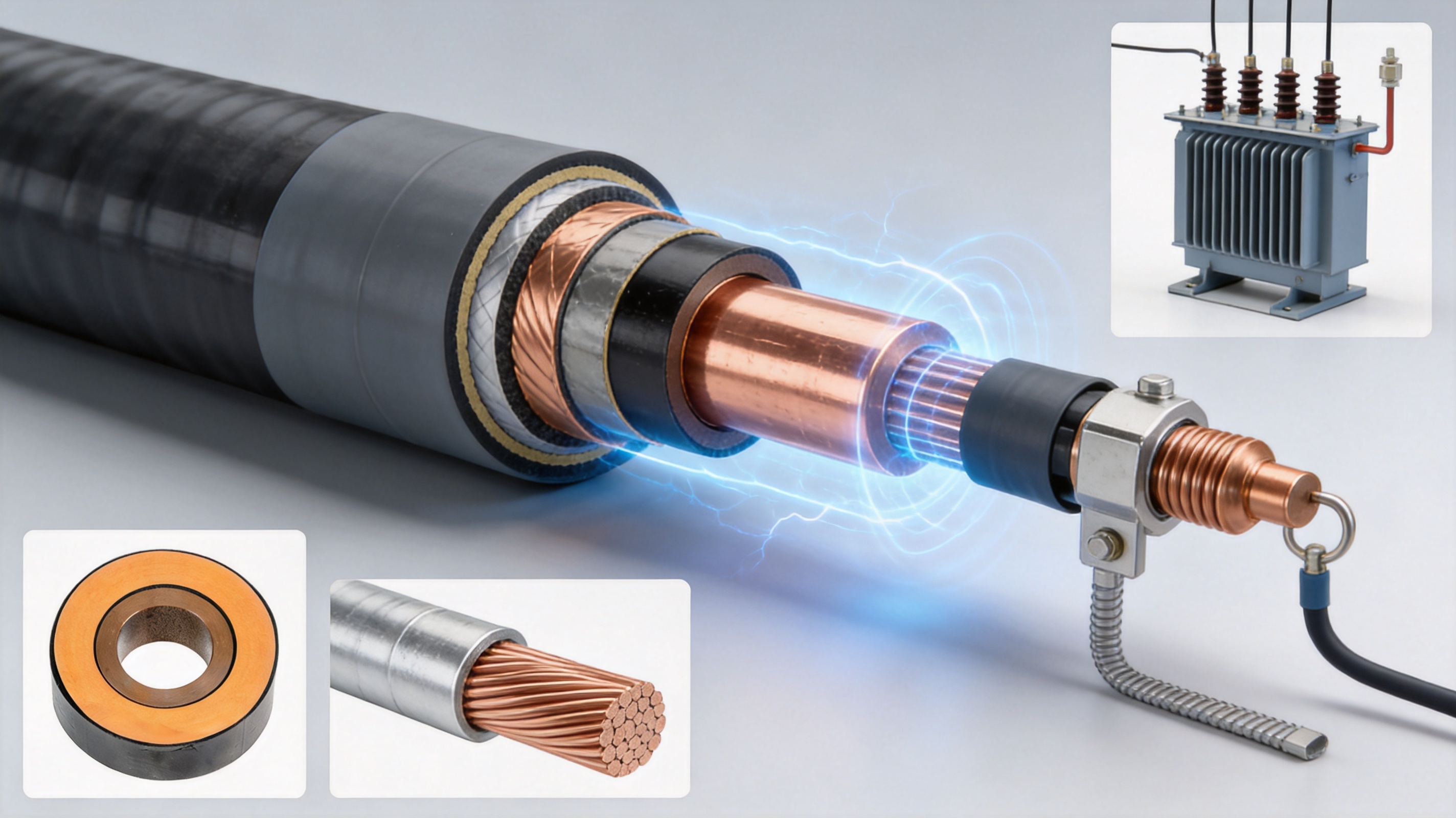
5. Shielded Intermediate Joint Technology
Intermediate joints are essential when the busbar route exceeds the available manufacturing length or must be divided for transport and installation. The joint must restore mechanical continuity, current-carrying capability, insulation, shielding, and environmental protection. A weak joint can reduce the performance of an otherwise high-quality insulated busbar, so joint design is a central part of the complete system.
5.1 Stainless Steel Inner Sleeve Connection
In the described joint structure, the conductor ends make direct contact through a stainless steel inner sleeve. The sleeve supports a stable connection between the tubular conductors and provides a controlled internal interface. It is designed to maintain current transmission while resisting deformation during assembly and operation.
Externally, two semicircular connecting bus bars secure the conductor connection. Four stainless steel C-clamps are tightened and welded using specialized tools or molds. This arrangement provides mechanical stability and helps maintain the required contact pressure. It also reduces the risk of conductor movement or shape distortion during installation.
5.2 Current-Carrying Performance
Current-carrying capacity depends not only on the conductor cross-section but also on the quality of every connection. Contact resistance at the joint must remain low enough to control heat generation. The joint components, tightening method, welding process, and inspection procedure must therefore be carefully controlled.
A reliable joint avoids localized heating and supports the continuous current rating of the complete busbar. It also helps withstand thermal expansion and contraction during load changes. The use of dedicated connection tools improves repeatability compared with improvised field assembly methods.
5.3 Shield Continuity and Waterproofing
After the conductor connection is completed, the insulation and shielding layers are restored around the joint. The joint is designed as a shielded structure so that the fully insulated line remains electrically continuous. Special waterproofing treatment can provide short-term resistance to submersion, allowing the busbar to continue operating briefly if water enters a trench or similar installation area.
Waterproofing is not a substitute for drainage, sealing, or permanent flood protection. However, it provides an additional safety margin in installations where temporary water exposure may occur. The joint design is particularly valuable for underground cable trenches, cable mezzanines, and other areas where moisture control is a practical concern.
6. Main Advantages over Conventional Busbar and Cable Solutions
The product competes with several alternatives, including exposed rigid busbars, PVC-insulated busbars, ceramic-insulated busbars, and conventional power cables. Each alternative can be appropriate in certain conditions, but the EPDM silicone rubber tubular bus bar offers a balanced combination of insulation, environmental resistance, mechanical stability, compact routing, and customization.
| Characteristic | EPDM Silicone Rubber Tubular Bus Bar | PVC Insulated Bus Bar | Ceramic Insulated Bus Bar | Conventional Cable Arrangement |
|---|---|---|---|---|
| Insulation structure | Composite shielded insulation with co-extruded layers | Polymer insulation, generally less suitable for severe UV exposure | Rigid ceramic insulation | Layered cable insulation and shielding |
| Environmental resistance | Strong resistance to ozone, UV radiation, moisture, and many chemicals | More vulnerable to UV aging depending on formulation | Good environmental resistance but vulnerable to impact and brittleness | Depends on cable jacket and installation protection |
| Mechanical behavior | Stable tubular route with designed flexibility at connections | Moderate | Rigid and brittle under impact | Flexible but may require extensive support and bending control |
| Electric-field control | Conductor shield, insulation shield, stress cones, and shielded joints | Varies by product and voltage class | Strong dielectric performance but sensitive to mechanical damage | Typically strong when correctly terminated |
| Installation efficiency | Compact, prefabricated terminals and specialized joints | Moderate | Requires careful handling and alignment | May require multiple cables, supports, cleats, and larger routing space |
| Typical service potential | Approximately 25 to 35 years when correctly designed and maintained | Approximately 10 to 15 years in demanding exposure conditions | Approximately 20 to 25 years, subject to mechanical conditions | Depends substantially on cable type, loading, environment, and termination quality |
6.1 High Insulation Performance
The composite insulation system is designed to provide high dielectric strength. A representative breakdown strength of at least 25kV/mm is associated with the described product configuration, although actual values depend on material formulation, test method, thickness, and applicable standards. The shielding system further supports predictable electric-field control.
Compared with basic PVC insulation, EPDM-based insulation can provide stronger performance in high-temperature, outdoor, and ozone-rich environments. Compared with ceramic insulation, it offers greater flexibility and lower risk of fracture during transportation, installation, or vibration.
6.2 Excellent Weather and Chemical Resistance
Outdoor substations and industrial plants may expose electrical equipment to rain, snow, sunlight, ozone, salt, dust, oils, and chemical vapors. EPDM rubber is recognized for its resistance to ozone and weathering. This makes the tubular bus bar suitable for exposed or semi-exposed routes when the complete system is correctly selected and installed.
Coastal applications can benefit from the sealed and shielded construction because the conductor and primary insulation are protected from direct environmental exposure. Chemical plants and metallurgical facilities can also use the product where ordinary insulation materials may age rapidly. A project-specific chemical compatibility review remains advisable for aggressive solvents or unusual process chemicals.
6.3 Compact Installation
Because the energized conductor is fully insulated, the busbar can often be routed more compactly than an exposed phase conductor arrangement. This can reduce the required electrical clearance and make it easier to connect equipment in crowded substations, switch rooms, and industrial plants.
The tubular structure also provides a clean and orderly appearance. A defined route can simplify support design, inspection, and future maintenance. In cable trenches and mezzanines, the busbar may provide a clearer arrangement than multiple large-diameter cables with complex support systems.
6.4 Reduced Installation Risk
Prefabricated cold-shrink terminals and prepared joint components help reduce the number of complex field operations. The installer does not need to construct every insulation layer manually. Factory-controlled components can improve consistency, provided that the site team follows the installation instructions and uses the correct tools.
Fully insulated construction also reduces the possibility of accidental contact with energized conductors during normal operation. This does not remove the need for grounding, isolation, lockout procedures, and electrical safety controls, but it contributes to a safer overall installation.
6.5 High Current-Carrying Capability
The solid tubular conductor is designed for high-current operation. Copper and aluminum options allow the system to be optimized for conductivity, weight, and cost. Terminal adapters and intermediate sleeves are engineered to maintain a low-resistance current path, while the tubular geometry supports thermal management.
For high-current systems, the final design should consider continuous load, emergency loading, short-circuit duration, ambient temperature, enclosure effects, ventilation, and heat transfer to nearby structures. A qualified manufacturer can calculate the correct conductor size and confirm the thermal performance of the complete route.
7. Typical Applications
The EPDM silicone rubber tubular bus bar can be used in a wide range of power distribution and industrial environments. The most appropriate application depends on voltage level, current, route configuration, environmental exposure, and connection requirements.
7.1 Substations and Switchgear Connections
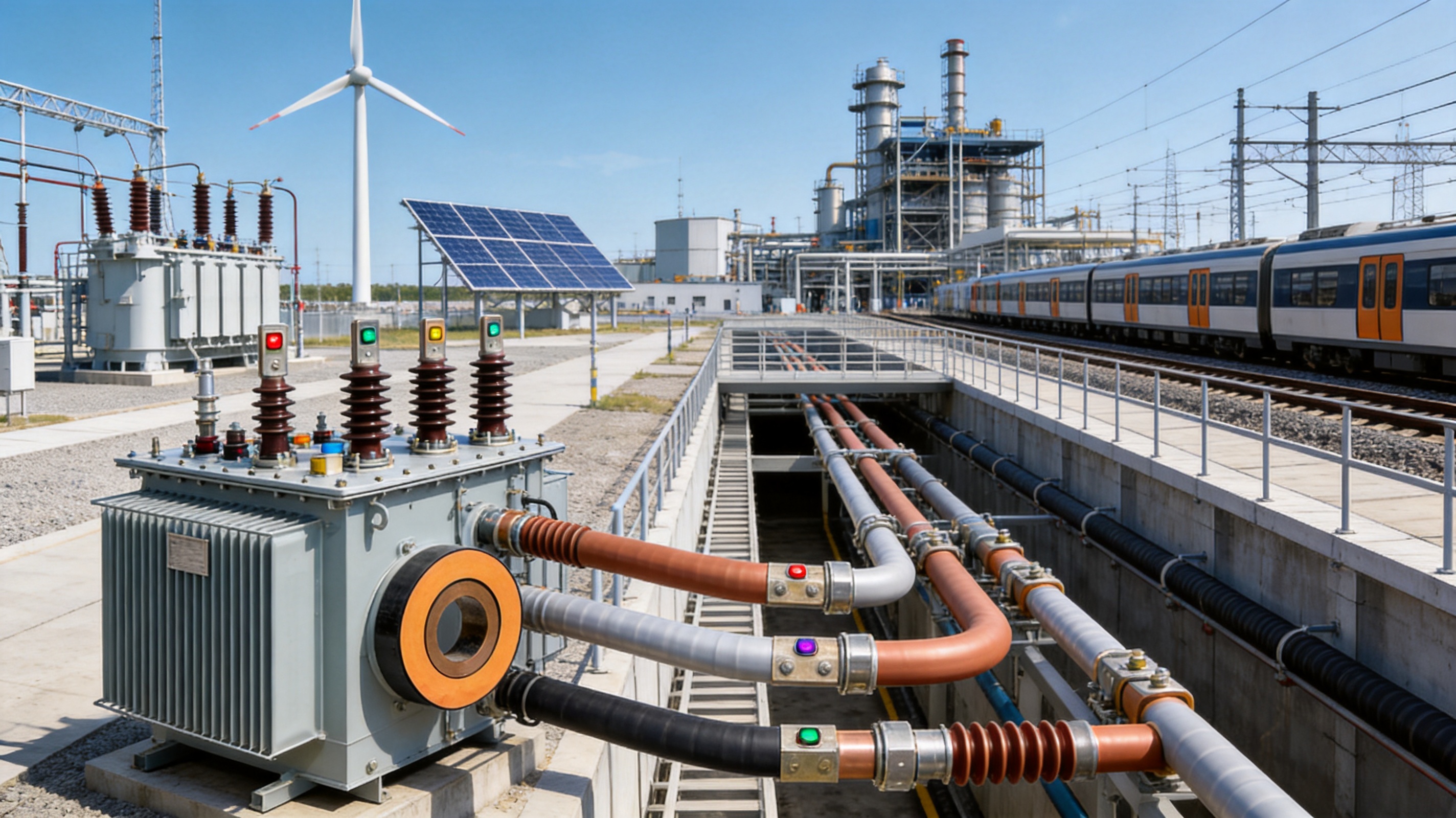
One of the most common applications is the connection between a main transformer and a low-voltage or medium-voltage switchgear cabinet. The busbar can provide a direct, high-current path from the transformer terminal to the switchgear terminal. This arrangement is suitable for projects that require clear routing, high current capacity, and a fully insulated connection.
The product can also connect circuit breakers, sectionalizers, distribution cabinets, and other substation equipment. Its compact layout is useful where transformer spacing and switchgear room dimensions are limited.
7.2 Cable Trenches and Cable Mezzanines
Routing the tubular busbar through a cable trench or cable mezzanine provides an alternative to overhead or exposed conductor arrangements. The busbar can connect switch cabinets positioned at different points in a plant or substation. Its sealed and shielded form is particularly useful where the route may encounter dust, moisture, or occasional water exposure.
The line can be designed around existing trench geometry and access points. Intermediate joints allow the route to be divided into manageable sections for transportation and installation.
7.3 Industrial Manufacturing Facilities
Metallurgical plants, chemical facilities, electronics factories, and other high-load industrial sites often require reliable power connections in areas exposed to vibration, heat, dust, or corrosive substances. The tubular busbar can connect transformers, motor control centers, distribution cabinets, and process equipment.
Its environmental resistance and compact form can be beneficial when conventional cable trays would become congested. The designer should evaluate the effects of process chemicals, radiant heat, mechanical impact, and maintenance access before final selection.
7.4 Wind Power and Renewable Energy Stations
Wind power installations require electrical connections that can withstand vibration, temperature variation, and restricted installation space. Tubular busbars can be used in wind turbine electrical systems and associated substations, subject to the specific turbine design and voltage requirements.
Solar power stations and renewable energy collection systems may also use tubular busbars to connect transformers, inverters, switchgear, and grid interconnection equipment. Outdoor weather resistance is especially valuable in solar and wind environments where direct sunlight, rain, and changing temperatures are common.
7.5 Rail Transit and Large Commercial Facilities
Rail transit facilities, infrastructure projects, and large commercial buildings often need compact and reliable high-current distribution. The busbar can be integrated into electrical rooms, utility corridors, cable mezzanines, or dedicated service routes. Its clean arrangement and shielded construction support projects where space, safety, and maintainability are important design considerations.
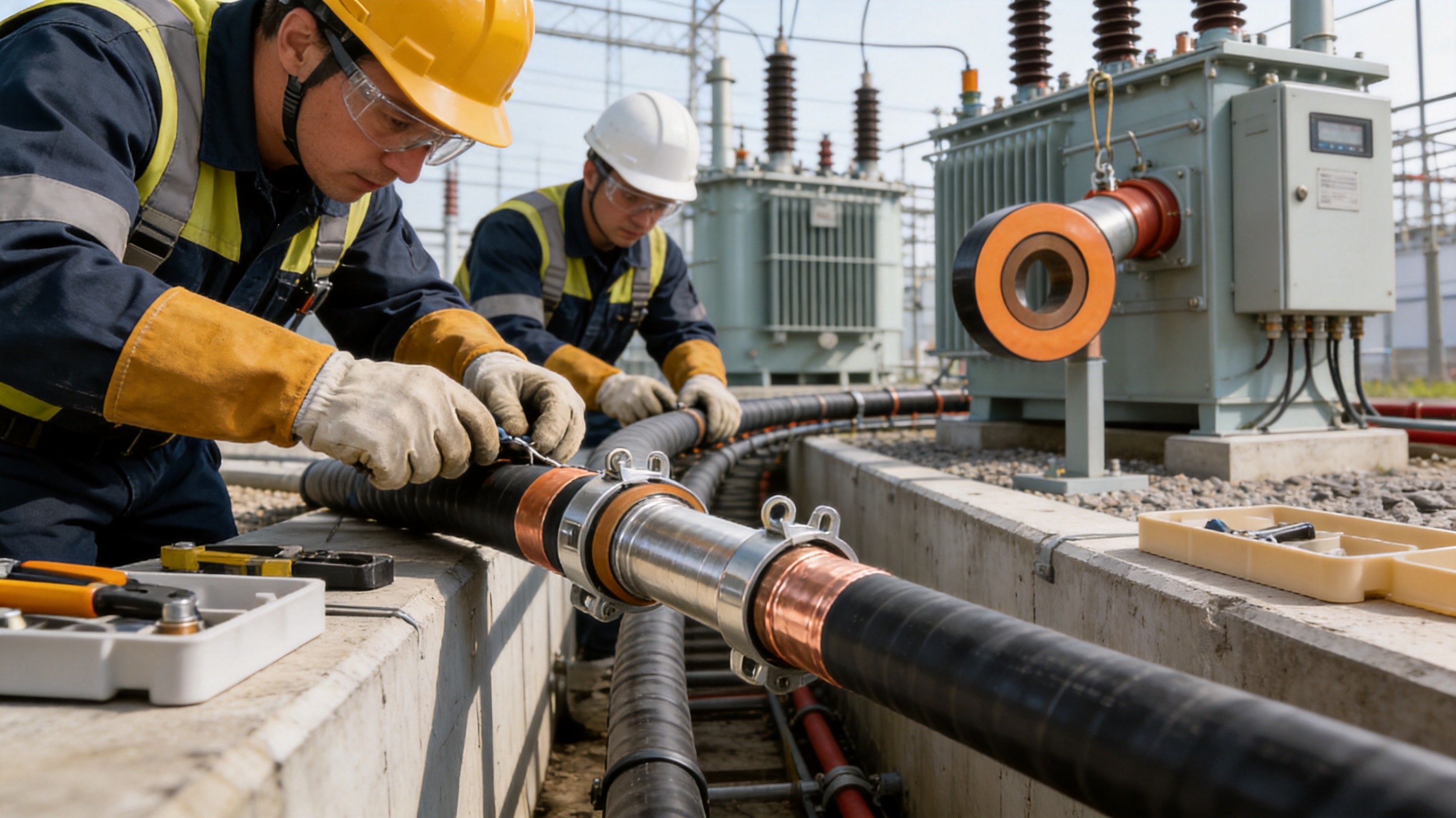
8. Application Configuration Options
Several common routing methods can be used depending on the project layout. The first method connects the main transformer directly to the control room or switchgear terminals. This is often preferred for large-current applications because it provides a direct and visually clear connection.
The second method routes the busbar through an underground cable trench or cable mezzanine. This configuration is suitable when the equipment is separated by walls, floors, or restricted corridors. It can also be used to connect several switch cabinets in a coordinated distribution system.
The third method uses the top cable connection point of the switch cabinet or a bottom cable connection route through a cable mezzanine. The choice depends on the cabinet design, available access, cable trench depth, maintenance requirements, and the direction from which the tubular busbar approaches the equipment.
The fourth method integrates a monitoring system for tubular busbar operation. Intelligent monitoring can be configured to observe selected technical data, such as temperature, operating status, and other parameters defined by the project. This supports condition-based maintenance and helps operators identify abnormal trends before they develop into failures.
8.1 Design Coordination
Before production, the manufacturer and customer should confirm the route drawing, phase arrangement, terminal orientation, conductor material, current rating, voltage class, support locations, joint positions, grounding arrangement, expansion requirements, and access for installation.
Accurate interface information is particularly important where the busbar connects directly to transformers or switchgear. Flange dimensions, bolt patterns, phase spacing, terminal height, equipment tolerances, and allowable mechanical loads should be reviewed in advance.
8.2 Thermal Expansion and Mechanical Movement
Conductors expand when their temperature rises. Transformers and switchgear may also experience small mechanical movements caused by vibration, switching forces, or thermal changes. Terminal adapters and flexible expansion joints help accommodate these movements while protecting the conductor and insulation system.
For long routes, engineers should evaluate support spacing, conductor deflection, thermal expansion, seismic conditions, and short-circuit electromagnetic forces. The complete support system must be designed together with the busbar rather than treated as a separate construction detail.
9. Manufacturing Strengths and Quality Management
A dependable insulated busbar requires more than high-quality raw materials. It requires controlled engineering, stable processing, accurate assembly, traceable inspection, and practical field support. Jiangsu Wopeng Power Technology Co., Ltd. was founded in 2018 as a specialized high-tech enterprise focused on high- and low-voltage busbar systems.
The company has developed a product portfolio serving power generation, substations, wind energy, industrial manufacturing, rail transit, and large commercial facilities. Its products include 35kV epoxy resin vacuum-cast tubular busbars, low-voltage epoxy-cast busway systems, copper and aluminum tubular busbars, wind power tube busbars, compact busbar systems, and sliding contact line power supply systems.
9.1 Engineering and Technical Team
The company’s engineering and production personnel have experience in power equipment technology, busbar design, insulation systems, mechanical connection, and project customization. This engineering foundation allows the manufacturer to evaluate unusual installation conditions rather than limiting customers to standard catalog dimensions.
Technical support may include conductor selection, insulation coordination, terminal design, joint positioning, route optimization, support recommendations, installation guidance, and test documentation. For OEM projects, engineering collaboration can begin with a customer drawing or a description of the required electrical connection.
9.2 Advanced Production Equipment
Modern production lines include vacuum casting systems, CNC machining equipment, automated assembly technologies, and extrusion-related manufacturing capabilities. Vacuum casting is used for selected epoxy resin busbar products, while CNC machining supports accurate preparation of conductor components, terminal adapters, connection parts, and mechanical interfaces.
Automated and semi-automated assembly processes improve repeatability and reduce variation in component positioning. Dedicated joint tools and specialized molds support consistent installation of stainless steel C-clamps and connection components.
9.3 Inspection and Testing
Each product undergoes standardized inspection procedures appropriate to its design. These may include high-voltage tests, insulation resistance tests, dimensional inspections, mechanical verification, conductor resistance checks, joint inspection, and routine quality checks.
High-voltage and insulation tests help verify the integrity of the insulation system. Mechanical verification confirms that the assembly can withstand expected handling and operating forces. Dimensional checks confirm that the finished busbar will match the approved interface drawings.
Testing collaboration with third-party institutions provides additional independent validation for selected products and projects. This is useful when customers require documented verification beyond routine factory inspection.
9.4 Project Experience
Wopeng products operate across more than 17 provinces and multiple industrial sectors. This application experience provides practical knowledge of different climates, installation methods, customer specifications, and operating environments. Experience in real projects can help identify installation risks early and support more effective product customization.
10. Customization Process for OEM Projects
A professional manufacturer should treat a tubular busbar as an engineered system rather than a generic commodity. The customization process normally begins with technical data collection. The customer provides voltage, current, frequency, route length, equipment interface drawings, environmental conditions, installation method, and required delivery schedule.
The manufacturer then prepares a preliminary design covering conductor material, conductor dimensions, insulation structure, shielding arrangement, terminal type, joint type, support requirements, and monitoring options. The design is reviewed against electrical, thermal, mechanical, and installation requirements.
10.1 Key Information Required from the Customer
Important information includes system voltage, continuous current, short-circuit withstand requirements, number of phases, phase sequence, conductor preference, indoor or outdoor installation, ambient temperature, altitude, exposure to water or chemicals, route geometry, bend requirements, terminal dimensions, and equipment manufacturer information.
Customers should also identify whether the system requires full shielding, special grounding arrangements, fire-performance requirements, seismic design, intelligent monitoring, or specific national and international certifications.
10.2 Drawing and Approval Stage
After the initial technical review, the manufacturer produces route drawings, terminal drawings, joint drawings, and product specifications for approval. The approval stage is important because even a small change in equipment position or flange orientation can affect the final busbar length and connection arrangement.
Once the drawings are approved, production can proceed under controlled documentation. Any later changes should be reviewed formally so that manufacturing, testing, and installation records remain consistent.
10.3 Production, Testing, and Delivery
Production includes conductor preparation, extrusion or casting, machining, shielding and sheath formation, terminal assembly, joint component preparation, inspection, and packaging. Before delivery, the manufacturer completes the specified tests and prepares technical documents such as inspection records, installation instructions, drawings, and product certificates.
Packaging should protect the tubular busbar from impact, bending beyond its allowable radius, moisture, contamination, and damage to terminal components. Long or complex products may require lifting points and installation supports that are identified in the shipping documents.
11. Installation and Commissioning Considerations
Installation quality has a direct effect on the reliability of the completed system. The site team should inspect all delivered components before installation, verify part numbers and dimensions, protect insulation surfaces from contamination, and confirm that the route matches the approved drawing.
Conductor preparation must be completed with suitable tools. Cutting, cleaning, stripping, and surface preparation should follow the manufacturer’s instructions. Excessive force, sharp tools, contamination, or incorrect stripping dimensions can damage the insulation and compromise the terminal or joint.
11.1 Terminal Installation
Cold-shrink terminal components should be stored and handled according to the specified conditions. The installer should confirm the correct position of the stress cone, shielding components, sealing elements, and connection hardware. The conductor adapter must be aligned accurately to avoid mechanical stress on the equipment terminal.
After installation, the terminal should be inspected for correct seating, surface condition, grounding continuity, sealing, and connection torque. The completed arrangement must maintain the required creepage, clearance, and access conditions.
11.2 Intermediate Joint Installation
Intermediate joints should be assembled in a clean and controlled work area. The stainless steel inner sleeve, semicircular connecting bus bars, C-clamps, shielding components, insulation components, and waterproofing materials must be installed in the specified sequence.
Specialized tools or molds should be used for tightening and welding the C-clamps. The joint should be inspected for conductor alignment, stable mechanical connection, correct shielding continuity, and complete waterproof treatment. Unapproved substitutions or improvised joint methods can reduce current-carrying capacity and increase the risk of failure.
11.3 Testing after Installation
Commissioning tests may include insulation resistance, conductor continuity, shielding continuity, grounding verification, withstand testing, phase identification, contact resistance, and visual inspection. The actual test program depends on the voltage level, project specification, and applicable standards.
Test results should be recorded and compared with factory documentation. Any abnormal result should be investigated before energization. After successful testing, the installation area should be checked for correct supports, access protection, labels, grounding connections, and clearance from unrelated equipment.
12. Maintenance and Service-Life Management
The tubular busbar is designed for long-term operation, but periodic inspection remains necessary. Maintenance programs should consider the operating environment, load level, water exposure, vibration, switching frequency, and accessibility of the installation.
Visual inspections can identify damaged outer sheaths, loose supports, corrosion on exposed hardware, signs of overheating, water ingress, contamination, or changes in joint position. Thermal imaging during normal operation can help identify abnormal temperature rise at terminals or intermediate joints.
Where monitoring sensors are installed, operators can track temperature and operating trends. A gradual increase in temperature at one joint may indicate increased contact resistance, a loose connection, an overloaded phase, or inadequate heat dissipation. Early detection allows maintenance before the problem develops into insulation damage or an outage.
12.1 Environmental Inspection
Outdoor and industrial installations should be inspected for ultraviolet aging, chemical deposits, mechanical impact, rodents, standing water, and damage caused by nearby construction. Although EPDM provides strong resistance to weather and ozone, the entire system, including sheath, seals, supports, and exposed metal parts, must be considered.
In cable trenches, drainage and ventilation should be maintained. Waterproofed joints can withstand short-term submersion after special treatment, but permanent flooding should be corrected as soon as possible. Long-term immersion may exceed the intended operating conditions of the complete installation.
12.2 Electrical Inspection
Electrical testing intervals should be established according to local regulations, the asset management plan, and the criticality of the circuit. Insulation resistance, shield continuity, grounding resistance, and selected withstand or diagnostic tests may be used to assess system condition.
Testing should be performed by qualified personnel using equipment suitable for the voltage class. The test method must be chosen carefully because inappropriate test voltage or procedure can damage insulation or produce misleading results.
13. Selection Guide for Project Engineers
Selecting the correct EPDM silicone rubber tubular bus bar requires coordination between electrical design, mechanical design, civil construction, and installation planning. The following factors should be considered before ordering.
13.1 Electrical Requirements
Confirm rated voltage, operating voltage, frequency, continuous current, short-time withstand current, peak withstand current, system grounding, insulation level, and required test voltage. The conductor material and size should be selected according to the electrical load and thermal calculation.
13.2 Environmental Requirements
Review ambient temperature, altitude, humidity, precipitation, ultraviolet exposure, salt contamination, chemical vapors, dust, vibration, and possible flooding. These factors influence the outer sheath, sealing method, support design, and installation location.
13.3 Mechanical Requirements
Identify the route length, bends, offsets, support spacing, expansion movement, equipment vibration, seismic conditions, and lifting limitations. Confirm the allowable mechanical load on transformer and switchgear terminals. Flexible expansion joints may be required where equipment movement or thermal expansion is expected.
13.4 Installation Requirements
Determine whether installation will take place indoors, outdoors, in a trench, on a mezzanine, or in a restricted equipment room. Confirm available working space, lifting access, joint locations, fire safety rules, water protection, and the tools available to the installation team.
13.5 Documentation and Compliance
Request technical specifications, approved drawings, material information, test reports, installation instructions, inspection records, and maintenance recommendations. The manufacturer should identify the standards used for design, manufacture, and testing. If the project requires third-party inspection or certification, this should be agreed before production.
14. Frequently Asked Questions
Q1: What is an EPDM silicone rubber tubular bus bar used for?
An EPDM silicone rubber tubular bus bar is used to transmit high electrical currents between transformers, switchgear, circuit breakers, distribution cabinets, generators, and other power equipment. It is especially useful in medium- and high-voltage systems where compact routing, full insulation, environmental resistance, and reliable joints are required.
Q2: What voltage range is suitable for this product?
The product is mainly used in 10kV to 35kV medium- and high-voltage systems. Customized designs may be developed for other voltage levels after reviewing insulation coordination, conductor dimensions, terminal structure, testing requirements, and the applicable project standards.
Q3: Is the conductor made from copper or aluminum?
Both copper and aluminum tubular conductors can be supplied. Copper is selected when high conductivity and strong connection performance are priorities. Aluminum can reduce overall weight and may provide an economical solution for suitable current and installation requirements.
Q4: What is the main advantage of triple-layer co-extrusion?
Triple-layer co-extrusion forms the conductor shield, primary insulation, and insulation shield in one coordinated process. It creates tight interfaces with reduced risk of gaps, improves dimensional consistency, and supports more uniform electrical performance than a less integrated assembly method.
Q5: Why are stress cones used at terminals?
Stress cones redistribute the electric field at the end of the insulated section. They reduce localized electric-field intensity at voltage concentration points, helping lower the risk of corona discharge, partial discharge, and progressive insulation damage.
Q6: Can the busbar be installed outdoors?
Yes. The EPDM-based insulation system is designed to resist weathering, ozone, ultraviolet radiation, moisture, and many common environmental contaminants. The complete outdoor installation must still include appropriate supports, sealing, grounding, drainage, and protection from mechanical damage.
Q7: Can it be used in coastal or chemical environments?
It can be suitable for coastal and industrial environments because EPDM provides strong resistance to ozone, ultraviolet exposure, and many chemicals. A project-specific compatibility assessment should be completed where the product may contact aggressive solvents, concentrated acids, strong alkalis, or unusual process chemicals.
Q8: Can intermediate joints withstand water exposure?
After special waterproofing treatment, intermediate joints can support short-term submerged operation. This feature provides additional protection in cable trenches and similar areas. It should not be interpreted as approval for permanent immersion, and drainage problems should be corrected promptly.
Q9: What is the maximum current-carrying capacity?
Representative standard models can carry up to approximately 3000A, while larger-capacity configurations may be available. The final rating depends on conductor material, conductor size, ambient temperature, installation conditions, voltage class, and the required thermal and short-circuit performance.
Q10: What information is needed for a quotation?
A quotation normally requires rated voltage, current, conductor material, route length, number of phases, terminal dimensions, equipment connection drawings, installation environment, route layout, joint requirements, monitoring requirements, delivery location, and applicable standards. Detailed information helps the manufacturer provide an accurate technical and commercial proposal.
Q11: How does this product compare with conventional cables?
The tubular busbar provides a defined rigid or semi-rigid route, high-current capability, compact installation, and integrated shielding. Conventional cables may offer greater flexibility over long or irregular routes, but high-current cable systems can require several parallel cables, larger support structures, more cleats, and complex termination arrangements. The best solution depends on the project route and electrical requirements.
Q12: Does fully insulated construction eliminate the need for grounding?
No. Fully insulated construction reduces exposure of energized parts, but grounding and bonding remain essential. The metal shielding, equipment enclosures, supports, and protective systems must be connected according to the approved design and applicable electrical safety requirements.
15. Why Choose a Specialized Manufacturer
A specialized tubular busbar manufacturer can coordinate conductor design, insulation technology, shielding, terminals, joints, mechanical supports, testing, and installation documentation as one system. This reduces the risk of incompatible components supplied by different vendors.
Jiangsu Wopeng Power Technology Co., Ltd. provides customized OEM solutions for insulated busbar and tubular busbar system projects. Its manufacturing capabilities include vacuum casting, CNC machining, automated assembly, controlled insulation production, and standardized inspection. Its product range supports both low-voltage and medium-voltage applications through 35kV.
The company’s experience across power generation, substations, wind energy, industrial manufacturing, rail transit, and commercial infrastructure enables it to address different project conditions. Customers can work with the engineering team to develop conductor sizes, terminal arrangements, route configurations, joint positions, and monitoring options according to the actual installation.
Quality management extends from raw material selection to final testing. High-voltage tests, insulation tests, mechanical verification, dimensional checks, and routine inspections help ensure that the finished product meets the approved technical requirements. Third-party testing cooperation can provide additional independent verification for demanding projects.
16. Conclusion
The EPDM silicone rubber tubular bus bar is a comprehensive power transmission solution for medium- and high-voltage systems. Its tubular copper or aluminum conductor provides a high-current path, while triple-layer co-extrusion integrates conductor shielding, EPDM primary insulation, and insulation shielding with tight interfaces. Metal shielding and a polyolefin outer sheath complete the protection system.
Prefabricated cold-shrink terminals, stress cones, terminal adapters, stainless steel inner sleeves, semicircular connecting bus bars, and shielded waterproof intermediate joints address the most important electrical and mechanical challenges at connection points. These features help control electric-field stress, maintain current-carrying performance, simplify installation, and improve resistance to moisture and environmental exposure.
Compared with PVC-insulated or ceramic-insulated alternatives, the product offers a balanced combination of insulation strength, weather resistance, flexibility, mechanical durability, and service-life potential. Compared with complex conventional cable arrangements, it can provide a more compact and orderly route for high-current connections.
With advanced manufacturing equipment, engineering expertise, standardized inspection, and OEM customization capabilities, Jiangsu Wopeng Power Technology Co., Ltd. is positioned to support projects requiring reliable insulated busbar systems. Proper technical selection, approved drawings, professional installation, and planned maintenance are essential to obtaining the full performance and service life of the product.
References
1. IEC 62271 series, High-voltage switchgear and controlgear.
2. IEC 60840, Power cables with extruded insulation and their accessories for rated voltages above 30kV up to 150kV.
3. IEC 60502 series, Power cables with extruded insulation and their accessories.
4. IEC 60071 series, Insulation coordination.
5. IEEE Standard 48, Standard for Test Procedures and Requirements for Alternating-Current Cable Terminations Used on Shielded Cables.
6. IEEE Standard 404, Standard for Extruded and Laminated Dielectric Shielded Cable Joints Rated 2500V to 500,000V.
7. Manufacturer technical specifications for composite shielded fully insulated tubular busbars.
8. Manufacturer installation and maintenance instructions for cold-shrink terminals and shielded intermediate joints.
Product: EPDM Silicone Rubber Tubular Bus Bar




-
 +86-180 3625 3000
-
 admin@wpbusbar.com
-
 No. 8, Yanjin Road, Chengxi Industrial Park, Shanyang Town, Baoying County, Yangzhou City, Jiangsu Province, China
Copyright © Jiangsu Wopeng Power Technology Co., Ltd.
All Rights Reserved.
 Custom Insulated Bus Bar Manufacturer
Tubular Busbar System Factory
Custom Insulated Bus Bar Manufacturer
Tubular Busbar System Factory