

 EN
EN

 English
 русский
 Français
 Español
 عربى
عربى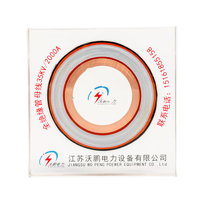
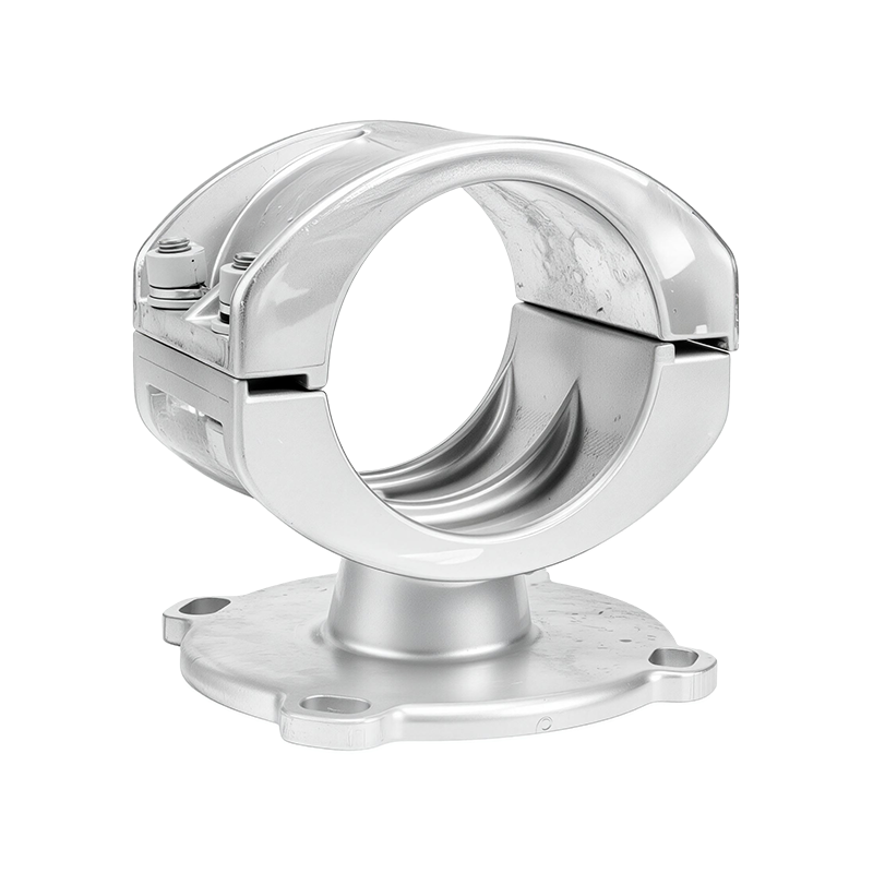
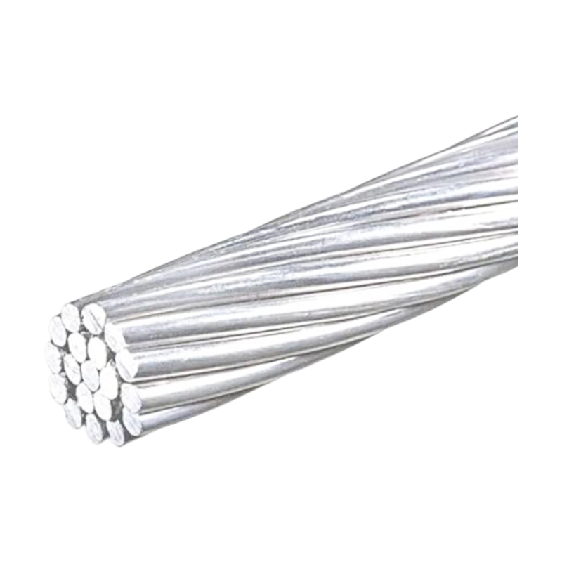
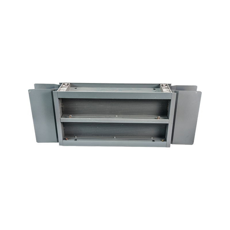
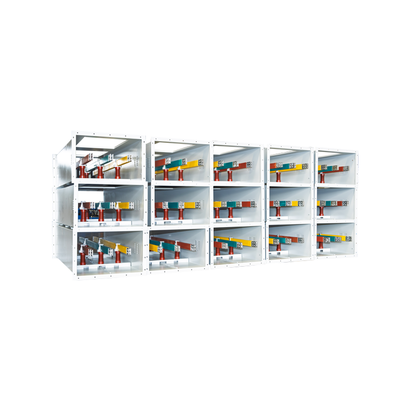


Post Insulators and Insulated Tubular Busbar Systems for Reliable Power Transmission
Content
- 1 1. The Role of Post Insulators in Electrical Systems
- 2 2. Insulated Tubular Busbars as an Integrated Alternative
- 3 3. Technical Advantages Compared with Conventional Rectangular Busbars
- 4 4. Environmental and Seismic Performance
- 5 5. Product Structure and Installation Principles
- 6 6. Manufacturing Technology and Quality Control
- 7 7. Comparison of Common Post-Insulator Materials
- 8 8. Product Advantages for Different Applications
- 9 9. Why a Specialized Manufacturer Matters
- 10 10. Advantages over Conventional and Low-Integration Competitors
- 11 11. Recommended Selection Process
- 12 12. Installation and Maintenance Recommendations
- 13 13. Service Life and Reliability Considerations
- 14 14. Frequently Asked Questions
- 14.1 Q1: What is the main purpose of a post insulator?
- 14.2 Q2: Can an insulated tubular busbar eliminate post insulators completely?
- 14.3 Q3: What is the advantage of a tubular busbar over a rectangular busbar?
- 14.4 Q4: What span can the tubular busbar achieve?
- 14.5 Q5: What is the recommended bracket spacing?
- 14.6 Q6: Can the system be used in polluted environments?
- 14.7 Q7: Is the product suitable for high-altitude projects?
- 14.8 Q8: What seismic conditions are covered by the design?
- 14.9 Q9: Which materials are commonly used for post insulators?
- 14.10 Q10: What manufacturing capabilities should a reliable supplier have?
- 14.11 Q11: Can the tubular busbar be customized?
- 14.12 Q12: What applications are suitable for insulated tubular busbars?
- 14.13 Q13: Does an integrated busbar system require maintenance?
- 14.14 Q14: How should customers begin a technical inquiry?
- 15 15. Conclusion
- 16 References
- 17 Product: Post Insulator
Modern electrical power systems require busbar assemblies that can carry high currents, withstand mechanical and environmental stress, simplify installation, and maintain stable insulation over many years. Post insulators have traditionally played an important role in supporting energized conductors and separating them from grounded structures. However, the development of insulated tubular busbar systems has created a more integrated approach in which the busbar itself, its insulation, and its support arrangement work together as a coordinated system.
In this type of application, post insulators may be reduced, replaced, or eliminated through structural optimization. Instead of relying on numerous independent insulator columns, an insulated tubular busbar can be fixed directly to steel structures or concrete supports with dedicated brackets. This arrangement provides mechanical stability, reduces the number of components, and allows the power transmission system to occupy less space. It also reduces the need for additional busbar fittings, foundations, wall bushings, and maintenance operations.
The combination of high-strength tubular conductors, insulation technology, engineered support brackets, and controlled manufacturing processes makes this solution suitable for substations, high-voltage rooms, current-limiting reactor connections, medium-voltage switchgear, wind power facilities, industrial plants, and other high-current applications. Jiangsu Wopeng Power Technology Co., Ltd. develops and manufactures high- and low-voltage busbar systems, including insulated tubular busbars, aluminum alloy tubular busbars, copper and aluminum tube busbars, epoxy resin vacuum-cast tube busbars, compact busbar systems, and related electrical power transmission products.
This article examines the function of post insulators, the structural advantages of insulated tubular busbars, the technical performance of optimized support systems, and the manufacturing strengths that distinguish a specialized busbar producer from conventional component suppliers.
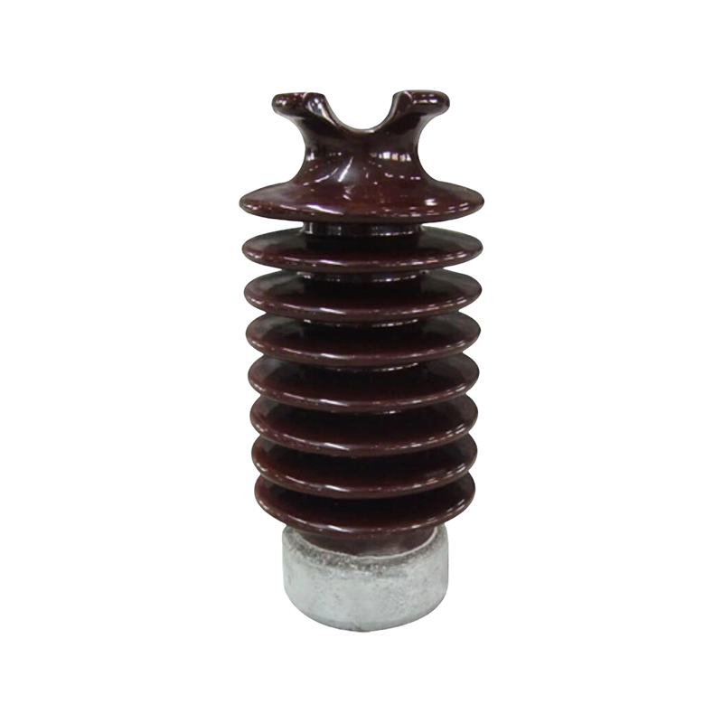
Post Insulator
1. The Role of Post Insulators in Electrical Systems
A post insulator is a rigid insulating component used to support a live conductor, busbar, disconnecting device, or other energized electrical equipment. It performs two essential functions at the same time. First, it provides mechanical support against the weight of the conductor, electromagnetic forces, vibration, and external loads. Second, it creates electrical separation between the energized component and the grounded steel structure, concrete foundation, enclosure, or neighboring phase.
Post insulators are widely used in indoor and outdoor substations, medium-voltage switchgear, high-voltage equipment, distribution cabinets, transformer stations, renewable energy installations, and industrial power distribution systems. Depending on the application, they may be manufactured from electrical porcelain, toughened glass, epoxy resin, silicone rubber, or other composite materials.
The selection of a post insulator depends on several technical factors. These include rated voltage, lightning impulse withstand level, power-frequency withstand voltage, creepage distance, pollution severity, mechanical bending load, environmental temperature, altitude, installation orientation, and seismic requirements. A suitable insulator must maintain its dielectric performance while also resisting mechanical deformation and environmental aging.
1.1 Electrical Isolation
The primary electrical purpose of a post insulator is to prevent leakage current and flashover between energized conductors and grounded structures. The insulating body must possess high insulation resistance and sufficient dielectric strength for the operating voltage. In practical systems, insulation performance is also affected by moisture, dust, salt deposits, industrial contaminants, condensation, ultraviolet radiation, and surface aging.
For this reason, electrical insulation cannot be evaluated only by the nominal voltage of the equipment. The installation environment must also be considered. Outdoor installations in coastal or industrial regions may require greater creepage distance, improved shed profiles, hydrophobic surfaces, or creepage extenders. The provided design information identifies suitability for pollution severity class V and specifies a design creepage distance ratio of 31 millimeters per kilovolt. For outdoor terminals, the total creepage distance after installing creepage extenders is not less than 680 millimeters.
1.2 Mechanical Support
In addition to insulation, a post insulator must withstand mechanical loads. These loads may include conductor weight, wind pressure, thermal expansion forces, short-circuit electrodynamic forces, installation loads, and seismic acceleration. The mechanical capacity of a post insulator is commonly expressed through a bending load or cantilever load rating.
Traditional busbar layouts often require several post insulators at relatively short intervals. Each support point must be correctly aligned and securely fixed. If the structure is not accurately installed, the conductor may experience uneven stress, connection misalignment, or unwanted vibration. In high-current systems, the electromagnetic force created during a short circuit can be particularly severe, making the spacing and strength of supports critical design considerations.
1.3 Limitations of Conventional Support Arrangements
Although conventional post insulators are reliable when properly selected and installed, a busbar system using many independent supports can become complicated. It may require separate foundations, mounting plates, bolts, alignment procedures, wall penetrations, phase spacing controls, and connection fittings. Every additional component creates another inspection point and another possible source of installation error.
Traditional arrangements may also require significant space. In compact substations, indoor switchgear rooms, industrial power centers, and renewable energy stations, the available installation area is often limited. A support system that occupies less space and integrates more functions can provide meaningful engineering and cost advantages.
Insulated tubular busbar technology addresses these issues by combining the electrical conductor, insulation structure, and mechanical support concept into a more integrated system. The result is not simply a replacement for one type of insulator. It is a different method of organizing the complete busbar installation.
2. Insulated Tubular Busbars as an Integrated Alternative
An insulated tubular busbar is a tubular conductor system designed to transmit electrical power while providing controlled insulation and mechanical support. Depending on the voltage level and project requirements, the conductor may be made from aluminum alloy or copper, while the insulation may use epoxy resin, cast resin, composite materials, or another engineered insulating structure.
The tubular geometry provides several inherent advantages compared with a conventional rectangular busbar. A tube has a favorable strength-to-weight ratio and distributes mechanical stress around its circumference. This allows the conductor to resist bending and deformation more effectively. The hollow internal structure can also reduce weight while retaining a high level of mechanical rigidity.
In the supplied technical design, the allowable stress of the insulated tubular busbar is described as four times that of rectangular busbars. Under a short-circuit current of 50 kA, a tubular busbar with a diameter of 100 millimeters and a wall thickness of 6 millimeters can achieve a suspended span of up to 9 meters. When supported by busbar brackets, the span can reach up to 13 meters.
These span capabilities can significantly change the layout of a power installation. Longer spans mean fewer intermediate supports, fewer foundations, reduced material consumption, and a cleaner installation. They may also allow a direct connection to high-voltage rooms, indoor current-limiting reactors, or 10 kV switchgear cabinets without the same number of post insulators and transition fittings required in a conventional design.
2.1 Direct Fixing to Steel and Concrete Structures
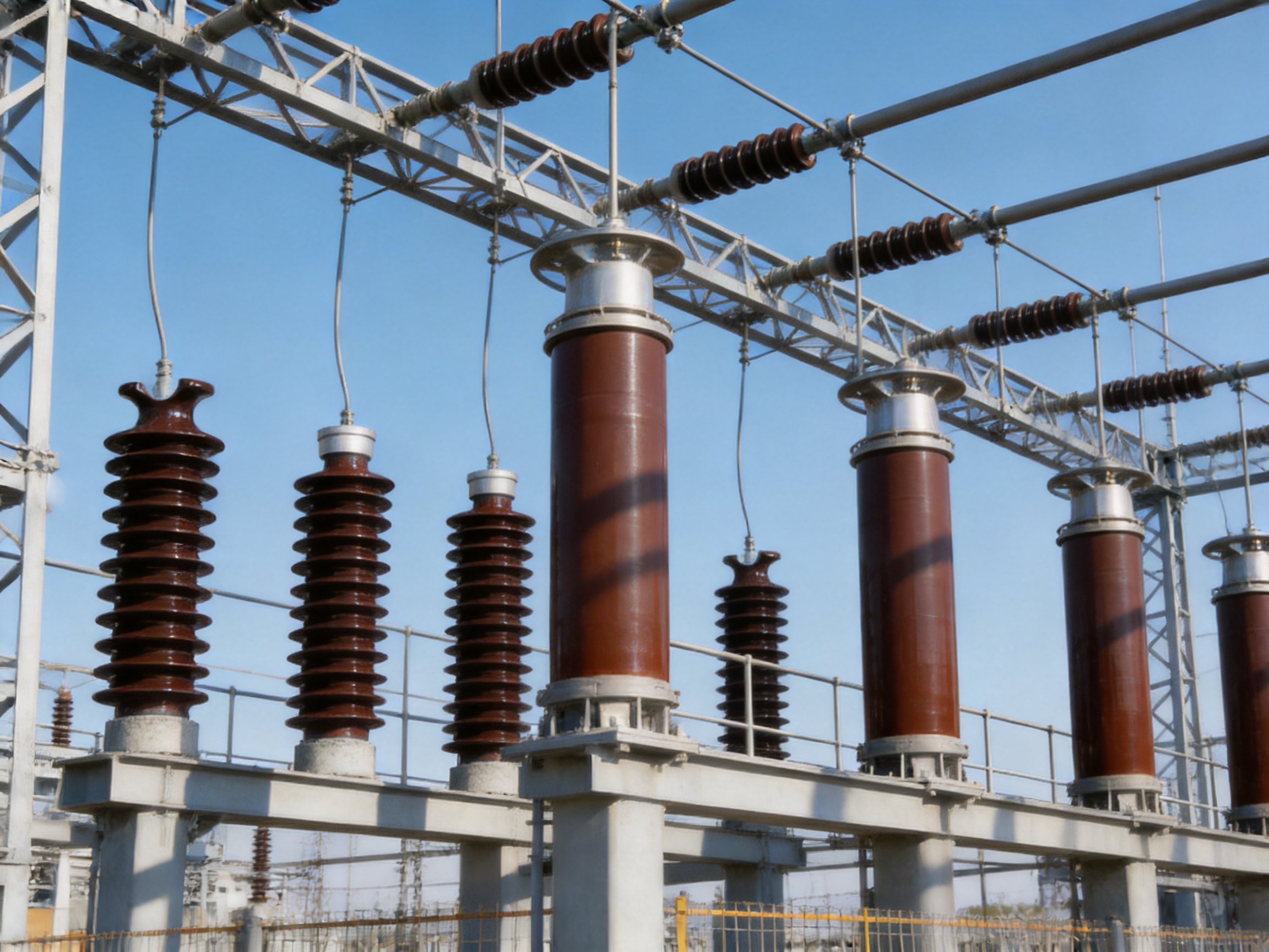
The insulated tubular busbar can be directly fixed to steel structures or concrete supports with dedicated support brackets. This arrangement minimizes the dependence on separate post-insulator columns and simplifies the load path between the conductor and the building or equipment structure.
Direct fixing must always be based on a complete mechanical and electrical design. The support structure must have sufficient strength, the fixing points must be correctly aligned, and the busbar must have adequate clearance from grounded parts and adjacent phases. The bracket arrangement must also account for thermal expansion, short-circuit forces, vibration, and the allowable movement of the busbar.
The recommended exposed installation method uses dedicated tubular busbar brackets with a spacing of at least 275 millimeters. Fixed brackets are required for spans ranging from 6 to 13 meters. The use of fixed and guiding support points should be determined according to the project layout, conductor length, expansion behavior, and calculated mechanical forces.
2.2 Reduced Component Count
A conventional busbar installation may include post insulators, busbar clamps, support plates, wall bushings, expansion connectors, foundations, and multiple connection accessories. When an insulated tubular busbar is connected directly to equipment or building structures, many of these elements can be reduced.
Reducing the component count has several effects. The construction sequence becomes easier to organize. The number of bolted joints and alignment operations is reduced. The risk of incorrect assembly decreases. The design may require less structural steel and fewer concrete foundations. In addition, inspection and replacement activities become more straightforward because there are fewer separate components to examine.
This integrated approach is especially useful where installation time is limited or where the project must be constructed inside a restricted area. It can also be advantageous for retrofit projects, because the busbar can be designed around existing steelwork, switchgear, reactor rooms, or equipment interfaces.
3. Technical Advantages Compared with Conventional Rectangular Busbars
The performance of a busbar system should be evaluated as a complete combination of conductor geometry, insulation, support arrangement, connection design, and installation environment. Tubular busbars can offer important advantages over conventional rectangular busbars in mechanical performance, span length, space utilization, and system integration.
3.1 Higher Mechanical Strength
The circular cross-section of a tubular busbar distributes bending stress more evenly than a flat rectangular section. This geometry is beneficial when the conductor must span between supports or resist forces acting in different directions. It also reduces the tendency of the conductor to twist or buckle under mechanical loading.
According to the supplied product information, the allowable stress of the insulated tubular busbar is four times that of rectangular busbars. This high allowable stress is particularly valuable in systems exposed to large short-circuit currents. During a short circuit, phase conductors experience strong repulsive or attractive forces. If the support spacing is too large or the busbar lacks adequate stiffness, these forces may cause excessive deflection or damage to connection points.
The tubular design helps maintain conductor alignment and reduces the mechanical burden placed on individual support components. This does not eliminate the need for engineering calculations, but it provides a stronger structural basis for long-span applications.
3.2 Longer Support Spans
Longer support spans are one of the most visible benefits of tubular busbars. The stated performance of a 100 millimeter by 6 millimeter tubular busbar under a 50 kA short-circuit current is a suspended span of up to 9 meters, increasing to 13 meters with busbar bracket support.
Long spans can reduce the number of support points required across a substation bay or industrial power room. Fewer support points may translate into fewer post insulators, less steelwork, simpler foundations, and reduced installation labor. A long-span configuration can also improve access for inspection and maintenance by reducing obstacles beneath the busbar.
Span length must be confirmed for each project because the final value depends on conductor size, material, current level, fault duration, support configuration, temperature, seismic conditions, connection loads, and allowable deflection. The published values provide an important reference for design evaluation but should be verified through project-specific calculations.
3.3 Better Space Utilization
Conventional air-insulated busbar systems may require substantial clearance around each conductor and support assembly. When wall bushings, post insulators, and connection fittings are added, the overall arrangement can become wide and difficult to route.
An insulated tubular busbar offers a more compact and organized configuration. The conductor is protected by its insulation system, and the support brackets can be positioned according to a standardized installation method. This can help reduce the footprint of substations, switchgear rooms, reactor connections, and industrial distribution centers.
Compact construction is particularly important in urban substations, high-rise buildings, data centers, rail transit facilities, and large commercial projects. In these locations, a smaller electrical room can reduce building costs and make better use of valuable floor space.
3.4 Direct Equipment Connection
The insulated tubular busbar can be directly connected to high-voltage rooms, indoor current-limiting reactors, or 10 kV switchgear cabinets. Direct connection reduces the number of transition components between the busbar and the equipment terminal.
Every transition creates potential electrical, mechanical, and thermal design challenges. A direct or highly integrated connection can shorten the current path, reduce connection interfaces, and improve the clarity of the installation. It can also reduce the amount of separate support hardware required around equipment terminals.
Direct connection must be carefully coordinated with equipment manufacturers. Terminal dimensions, allowable loads, electrical clearances, expansion movement, grounding arrangements, and inspection access must all be confirmed before production.
3.5 Lower Maintenance Requirements
Traditional outdoor post-insulator systems may require periodic cleaning, contamination inspection, crack detection, hardware tightening, and electrical testing. The maintenance burden increases in coastal, industrial, desert, or heavily polluted environments.
A fully insulated tubular busbar can reduce exposure of the energized conductor and decrease the number of exposed insulator surfaces. Fewer independent support components mean fewer parts requiring routine inspection. The integrated structure also reduces the number of mechanical joints that may loosen or corrode over time.
Maintenance is not eliminated entirely. Operators must still inspect the busbar surface, brackets, connections, grounding arrangements, expansion points, and surrounding structures. However, the system can reduce the frequency and complexity of maintenance when compared with a more fragmented conventional arrangement.
4. Environmental and Seismic Performance
Power transmission equipment must remain stable under a combination of electrical, mechanical, and environmental stresses. A product that performs well in a clean indoor room may require additional design measures for outdoor or heavily polluted conditions. The insulated tubular busbar and its support system are designed for demanding operating environments, including high altitude, severe pollution, vibration, and seismic loading.
4.1 Pollution Resistance
Pollution deposits can form a partially conductive layer on an insulator surface. When the surface becomes wet, leakage current increases and may develop into dry-band arcing or flashover. Pollution resistance therefore depends on surface profile, material properties, creepage distance, hydrophobicity, voltage level, and environmental exposure.
The product design is identified as suitable for pollution severity class V, described as heavy pollution. The stated creepage distance ratio is 31 millimeters per kilovolt. Outdoor terminal creepage extenders can increase the total creepage distance to not less than 680 millimeters.
These provisions are useful for coastal regions, chemical plants, cement factories, steel mills, mining operations, and other sites where salt, dust, smoke, or industrial contaminants may accumulate. The final insulation coordination should still be confirmed according to the actual site conditions and applicable project requirements.
4.2 High-Altitude Operation
The design is suitable for altitudes up to 4,000 meters. At higher elevations, air density decreases, which affects external insulation performance and the ability of air gaps to withstand electrical stress. Equipment installed at high altitude may require increased clearances, adjusted insulation coordination, or special verification.
An insulated tubular busbar system designed for high-altitude use can provide greater flexibility for hydropower stations, mountain substations, highland wind farms, mining facilities, and remote industrial plants. The project designer should identify the site elevation at the beginning of the specification process so that insulation, cooling, and mechanical requirements can be incorporated into the product configuration.
4.3 Seismic Requirements
The post-insulator and support design considers seismic operating conditions. The supplied technical values include a horizontal acceleration of 0.20 g, a vertical acceleration of 0.15 g, a vibration frequency of 20 Hz, and tolerance to three sine-wave cycles. The stated safety factor is greater than 1.67.
These parameters are important because seismic motion can create simultaneous horizontal and vertical forces in the busbar, supports, equipment terminals, and building structures. The most demanding condition may occur when an earthquake coincides with a short-circuit event. Under that combined condition, the busbar must remain mechanically stable and electrically functional.
A tubular conductor with high stiffness can help maintain phase spacing and reduce excessive movement. The bracket system must also be designed to transfer forces safely without damaging the insulation or equipment terminals. For a complete seismic design, the support structure, foundation, connection hardware, and adjacent equipment must be evaluated together.
4.4 Vibration Resistance
Vibration may be generated by rotating machinery, transformers, reactors, wind turbines, transport systems, or nearby industrial equipment. Repeated vibration can loosen fasteners, fatigue metal parts, and create stress at electrical connections.
Direct structural fixing and a reduced number of separate components can improve vibration resistance. A properly designed bracket system distributes mechanical loads and keeps the tubular busbar securely positioned. The absence of unnecessary intermediate fittings also reduces the number of interfaces that could develop looseness over time.
5. Product Structure and Installation Principles
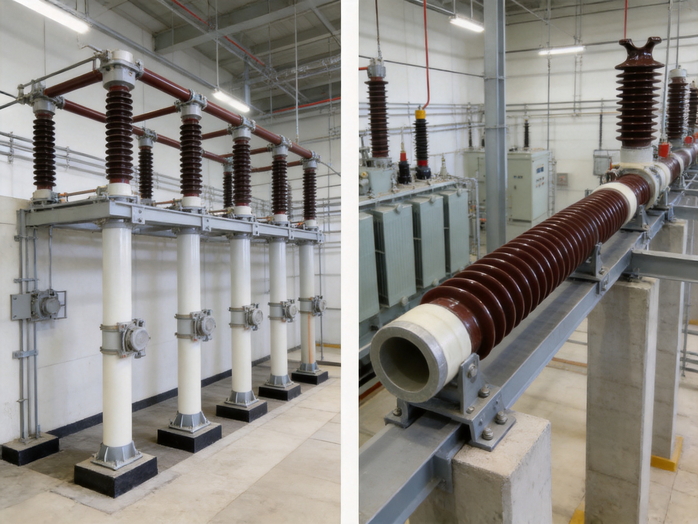
The insulated tubular busbar system consists of more than the conductor alone. Its performance depends on the coordinated design of the tubular conductor, insulation body, end connections, support brackets, fixed points, guiding points, grounding arrangements, and equipment interfaces.
5.1 Tubular Conductor
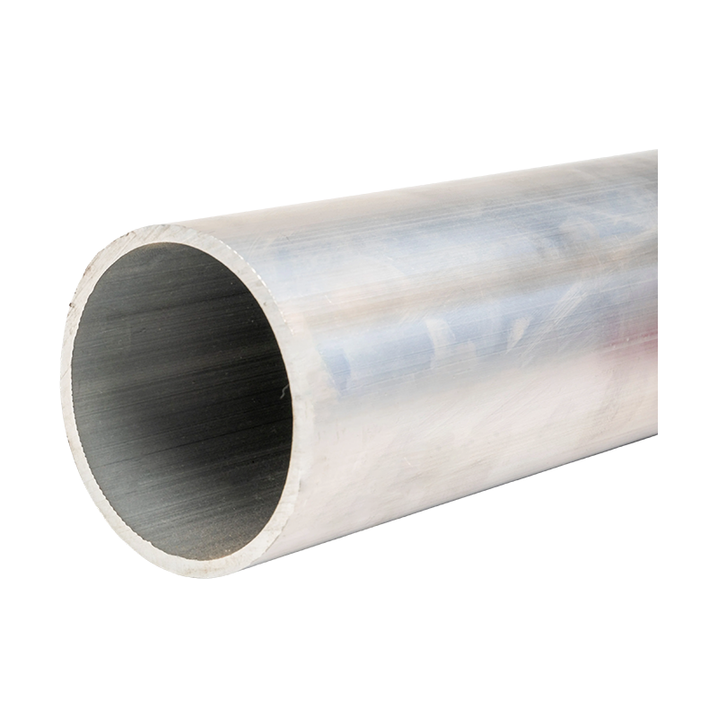
The conductor may be manufactured from aluminum alloy or copper, depending on current capacity, weight, conductivity, mechanical requirements, corrosion conditions, and project cost. Aluminum alloy tubular busbars are attractive for long spans because of their low density and favorable strength-to-weight ratio. Copper tubular busbars provide high electrical conductivity and can be selected where compact current-carrying capacity is a priority.
The diameter and wall thickness are selected according to continuous current, short-circuit current, temperature rise, mechanical span, fault duration, and connection requirements. The example of a 100 millimeter diameter and 6 millimeter wall thickness demonstrates the type of geometry used for high-strength applications, but the correct size must be determined for each project.
5.2 Insulation System
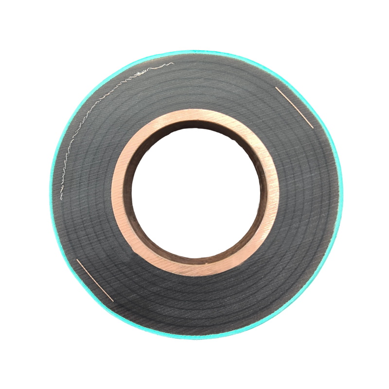
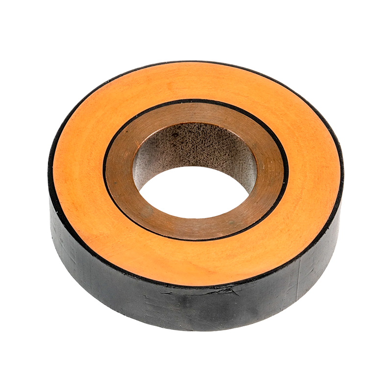
The insulation system separates the conductor from surrounding grounded structures and neighboring phases. Depending on the product type, the insulation may be based on epoxy resin vacuum casting, cast resin, composite materials, or other high-performance electrical insulation technologies.
Uniform insulation thickness is essential. Voids, cracks, moisture ingress, poor adhesion, and uncontrolled curing can reduce dielectric performance and create partial discharge risks. Advanced casting and curing processes help achieve consistent insulation quality around the tubular conductor.
5.3 Support Brackets
Dedicated tubular busbar brackets provide the mechanical connection between the insulated conductor and the building or steel structure. The recommended bracket spacing is at least 275 millimeters for exposed installation arrangements. Fixed brackets are installed for spans from 6 to 13 meters, while other supports may be configured to guide or accommodate movement.
Bracket design must take into account conductor diameter, weight, short-circuit force, thermal expansion, seismic acceleration, installation tolerance, and corrosion protection. The bracket material and surface treatment should be selected for the environmental conditions of the project.
5.4 Fixed and Movable Support Points
A busbar system must be supported without restricting thermal movement in an uncontrolled way. If every support point is rigidly fixed, thermal expansion may generate excessive axial stress. If the busbar is insufficiently restrained, movement may affect terminal connections or phase clearances.
For this reason, a complete support layout may include fixed brackets, guiding brackets, and expansion provisions. The exact arrangement depends on the length of each busbar section, operating temperature range, connection geometry, and structural layout. This engineering approach is one of the reasons why a specialized manufacturer is valuable: the product must be configured as a system rather than selected as an isolated component.
5.5 Installation Clearances
Although the busbar is insulated, electrical clearances must still be maintained around joints, terminals, grounded structures, and exposed connection areas. The installation design should consider phase-to-phase separation, phase-to-ground distance, access for testing, ventilation, cable interfaces, and the possibility of future expansion.
Installation drawings should identify support locations, bracket types, connection torque requirements, grounding points, terminal interfaces, and allowable mechanical loads. Clear documentation reduces installation errors and helps the operating team maintain the system correctly.
6. Manufacturing Technology and Quality Control
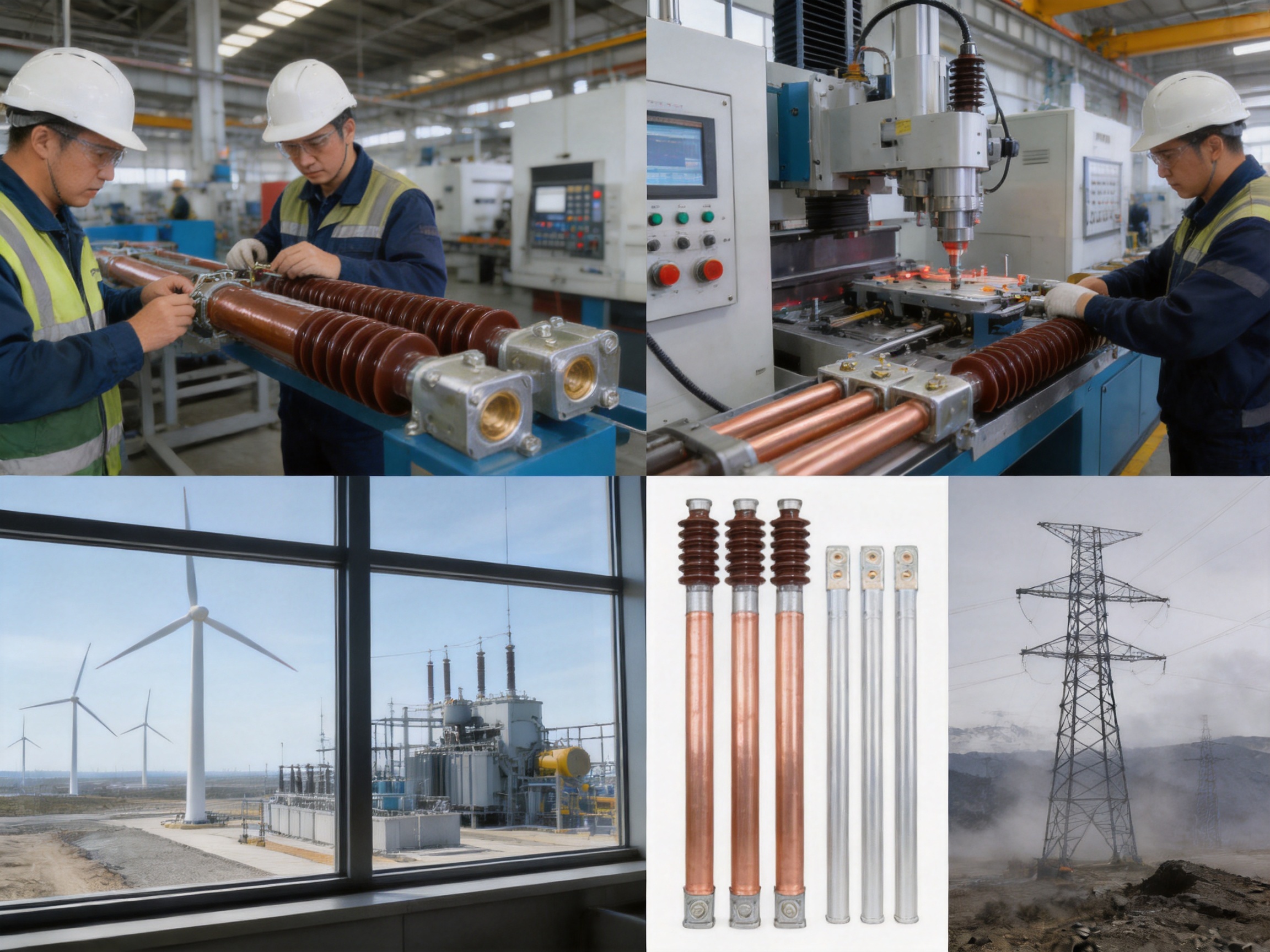
The reliability of an insulated tubular busbar depends heavily on manufacturing quality. A technically sound design can fail if the conductor is inaccurately machined, the insulation contains defects, the resin is improperly cured, or the final assembly is not correctly inspected. A specialized manufacturer therefore needs capabilities in material control, vacuum casting, precision machining, automated assembly, electrical testing, and mechanical verification.
6.1 Engineering and Customized Design
Jiangsu Wopeng Power Technology Co., Ltd. was founded in 2018 as a specialized high-tech enterprise focused on the development and manufacturing of high- and low-voltage busbar systems. Its engineering team supports customized solutions for different voltage levels, current ratings, installation environments, support spans, equipment interfaces, and space restrictions.
Customization may involve conductor dimensions, aluminum or copper selection, insulation thickness, terminal configuration, bracket arrangement, creepage extension, connection structure, installation orientation, or seismic requirements. The purpose of customization is not merely to change dimensions. It is to ensure that the complete busbar system matches the electrical and mechanical conditions of the project.
Engineering development begins with the application requirements. The manufacturer may review rated voltage, continuous current, short-circuit current, fault duration, ambient temperature, altitude, pollution level, seismic conditions, support span, terminal loads, and installation method. These parameters are then used to establish a product configuration and verification plan.
6.2 Vacuum Casting and Resin Insulation
Vacuum casting is an important process for epoxy resin vacuum-cast tube busbars and other cast-resin products. During vacuum casting, air and volatile substances are removed from the mold and resin system before or during filling. This helps reduce internal voids and improves the uniformity of the insulation body.
After casting, the resin must be cured according to a controlled temperature and time profile. Proper curing develops the required mechanical strength, thermal stability, adhesion, and dielectric properties. Inadequate curing can result in reduced strength or unstable electrical performance, while excessive or uneven curing can generate internal stress.
Process control may include resin viscosity monitoring, mixing ratio management, mold temperature control, vacuum level monitoring, curing temperature recording, and visual inspection of the finished surface. These controls are important because defects inside a solid insulation system may not be visible after assembly.
6.3 CNC Machining
CNC machining equipment supports the accurate manufacture of conductor ends, terminal interfaces, connection holes, transition pieces, and precision metal fittings. Dimensional accuracy is particularly important where the busbar must connect directly to a switchgear cabinet, reactor, transformer, or high-voltage room.
Accurate machining reduces assembly stress and improves contact quality. It also helps maintain consistent phase spacing and mounting alignment. CNC production allows repeatable processing across multiple product batches while retaining the flexibility required for customized orders.
6.4 Automated Assembly
Automated assembly technologies help improve consistency in the installation of brackets, connection components, insulation parts, and auxiliary fittings. Automation can reduce variation caused by manual operations and can make production records easier to maintain.
Automation does not replace engineering judgment or final inspection. Instead, it provides a stable production platform in which repeatable operations are performed under controlled conditions. Skilled technicians remain essential for process setup, dimensional verification, electrical testing, and nonconformance analysis.
6.5 Electrical Testing
Each product undergoes standardized inspection processes, including high-voltage tests, insulation tests, mechanical verification, and routine quality checks. Electrical testing helps verify that the finished busbar can withstand the specified voltage and maintain adequate insulation resistance.
Depending on the product configuration and project requirements, testing may include power-frequency withstand testing, insulation resistance measurement, partial discharge evaluation, conductor resistance checks, temperature-rise verification, and inspection of connection interfaces. Mechanical verification may include dimensional checks, bracket load assessment, torque inspection, and review of support alignment.
Testing collaboration with third-party institutions provides independent validation of safety and performance. External testing is especially useful for projects with demanding specifications, regulated procurement procedures, or high reliability requirements.
6.6 Traceability and Quality Management
A reliable manufacturing system should connect raw material records, production parameters, inspection results, and final product identification. Traceability allows the manufacturer to investigate issues quickly and supports long-term service and maintenance.
Quality management should cover incoming materials, conductor fabrication, insulation casting, curing, machining, assembly, electrical testing, packaging, and shipment. A controlled quality process reduces the risk that a product will meet its dimensional requirements but fail to deliver stable long-term electrical performance.
7. Comparison of Common Post-Insulator Materials
Post insulators may be produced from different materials. The correct choice depends on voltage level, mechanical loads, pollution conditions, weight limitations, installation environment, and required service life. The following table summarizes the general characteristics of common materials described in the supplied technical information.
| Material | Typical Voltage Range | Mechanical Characteristics | Environmental Performance | Common Advantages |
|---|---|---|---|---|
| Ceramic or porcelain | 1 kV to 550 kV | High mechanical strength and rigidity | Excellent weather resistance when properly designed | Established technology, strong electrical insulation, broad application history |
| Polymer or silicone rubber | 1 kV to 220 kV | Lightweight with high mechanical performance | Good anti-pollution and hydrophobic performance | Low weight, useful for difficult installation locations, good contamination resistance |
| Epoxy resin or cast resin | Application-dependent | High rigidity and good dimensional stability | Suitable for enclosed or controlled outdoor designs | Integrated insulation, accurate molding, compact equipment arrangements |
Porcelain remains widely used because of its established electrical and mechanical properties. Composite polymer materials can reduce weight and offer hydrophobic surfaces, which may be beneficial in polluted environments. Epoxy and cast-resin systems provide opportunities for integrated insulation and compact busbar construction.
However, comparing materials alone does not provide a complete evaluation. A tubular busbar system may reduce the total number of post insulators required because the conductor and insulation are combined into a more integrated assembly. Therefore, the comparison should consider the full installed system, including supports, foundations, fittings, maintenance, space requirements, and connection interfaces.
8. Product Advantages for Different Applications
8.1 Substations
Substations require reliable high-current connections between transformers, switchgear, reactors, bus sections, and outgoing feeders. Insulated tubular busbars can provide long, mechanically stable connections while reducing the number of independent support structures.
In a substation, the busbar may be installed outdoors on steel structures or indoors between equipment rooms. Its insulation helps improve installation organization, while its tubular strength supports long spans. The reduced need for wall bushings and post insulators can simplify the transition between indoor and outdoor sections.
8.2 Medium-Voltage Switchgear
Medium-voltage switchgear cabinets often have limited space around incoming and outgoing connections. A compact insulated tubular busbar can be adapted to the cabinet interface and routed through a confined area with fewer external support elements.
The ability to connect directly to 10 kV switchgear cabinets is particularly useful where the project requires a short, reliable, and mechanically secure connection. Proper coordination of terminal dimensions and insulation clearances is essential for safe operation.
8.3 Indoor Current-Limiting Reactors
Current-limiting reactors may generate strong electromagnetic forces and vibration during operation. Their connections must therefore be mechanically robust and capable of handling fault conditions.
An insulated tubular busbar provides a high-strength connection solution for indoor reactor rooms. Its integrated insulation can reduce the need for separate post-insulator supports, while the tubular geometry helps maintain alignment under short-circuit forces.
8.4 Wind Power Systems
Wind power installations are exposed to vibration, changing temperatures, remote locations, and demanding maintenance conditions. Tubular busbars are used in certain wind power applications because of their compact construction and ability to handle high currents within restricted equipment spaces.
A manufacturer with experience in wind power tube busbars can consider the special requirements of nacelle equipment, tower routing, transformer interfaces, vibration, transportation, and field assembly. Lightweight aluminum alloy designs may also reduce structural loading where appropriate.
8.5 Industrial Plants
Industrial facilities may contain motors, furnaces, welders, rolling equipment, compressors, and other high-current loads. The electrical distribution system must tolerate vibration, dust, heat, and frequent load changes.
Insulated tubular busbars can support high-current distribution while improving organization in electrical rooms and production areas. The reduction of exposed conductive surfaces and independent support parts may also contribute to safer and more manageable installations.
8.6 Rail Transit and Commercial Facilities
Rail transit facilities and large commercial buildings often place a premium on compactness, low maintenance, and dependable operation. Busbar systems may be installed in service corridors, substations, equipment rooms, or constrained structural spaces.
A modular tubular busbar arrangement can be engineered around building structures and equipment interfaces. The resulting system can reduce construction complexity and make future inspection more accessible.
9. Why a Specialized Manufacturer Matters
The performance of a busbar system is influenced by the relationship between electrical design, insulation technology, mechanical structure, and manufacturing accuracy. A company that only supplies isolated insulator components may not be able to optimize the complete busbar arrangement. A specialized busbar manufacturer can evaluate the conductor, insulation, support system, and equipment connection as one product.
Jiangsu Wopeng Power Technology Co., Ltd. focuses on high- and low-voltage busbar systems and offers a portfolio covering low voltage through 35 kV applications. Its products include 35 kV epoxy resin vacuum-cast tubular busbars, low-voltage epoxy-cast busbar trunking, copper and aluminum tubular busbars, wind power tube busbars, compact busbar systems, and sliding contact line power supply systems.
This product range provides an engineering advantage because different projects can be evaluated using experience from multiple busbar technologies. High-voltage cast-resin products, low-voltage busways, aluminum alloy tubular conductors, and specialized wind power systems each require different design considerations. Experience across these categories supports better material selection and application guidance.
The company has built a team of engineers, technical specialists, and production professionals with experience in power equipment technology. Its production facilities include vacuum casting systems, CNC machining equipment, and automated assembly technologies. These capabilities support both standardized products and customized OEM solutions.
Manufacturing experience is also important for project coordination. A busbar system must be designed to match the customer’s drawings, equipment terminals, support steelwork, transport restrictions, and construction schedule. A manufacturer that can provide engineering drawings, interface confirmation, inspection records, installation guidance, and technical communication can reduce project risk.
10. Advantages over Conventional and Low-Integration Competitors
10.1 Integrated System Design
One major advantage is the ability to design the conductor, insulation, and support method together. Low-integration competitors may provide a conductor or post insulator without fully addressing the surrounding structural system. An integrated design can reduce unnecessary components and improve compatibility between the busbar and the support structure.
10.2 Long-Span Capability
The stated 9-meter suspended span and 13-meter bracket-supported span under a 50 kA short-circuit condition demonstrate the mechanical potential of the tubular design. Longer spans can reduce the number of support locations compared with conventional rectangular busbars, although actual performance must be verified for each configuration.
10.3 Reduced Installation Complexity
The direct fixing method can eliminate or reduce wall bushings, post insulators, separate busbar fittings, and structural foundations. This may shorten the construction period and reduce labor associated with leveling, alignment, and multi-point fixation.
10.4 Better Adaptation to Severe Environments
Support for pollution severity class V, creepage-distance optimization, outdoor creepage extenders, and operation up to 4,000 meters demonstrate attention to difficult installation environments. Products that are designed only for clean indoor conditions may require extensive modification before they can be deployed in coastal, industrial, or high-altitude locations.
10.5 Customized OEM Production
Electrical projects rarely use a completely universal busbar geometry. Terminal positions, support distances, current ratings, voltage classes, and equipment interfaces differ from one project to another. The ability to provide custom dimensions, connection arrangements, insulation structures, and support components is therefore an important competitive advantage.
10.6 Manufacturing and Testing Resources
Vacuum casting systems, CNC machining, automated assembly, high-voltage testing, insulation testing, and mechanical verification give the manufacturer control over critical production stages. This is more reliable than depending on loosely coordinated subcontractors for conductor fabrication, insulation work, and final assembly.
11. Recommended Selection Process
Customers selecting a post-insulator-supported busbar or an insulated tubular busbar system should begin with a complete technical specification. The following factors should be reviewed before the product is finalized.
11.1 Electrical Parameters
The required rated voltage, continuous current, short-circuit current, short-circuit duration, power-frequency withstand voltage, lightning impulse withstand level, and insulation coordination should be established. These values determine the conductor size, insulation structure, phase spacing, and test requirements.
11.2 Mechanical Parameters
The designer should provide support spans, conductor weight, terminal loads, wind conditions, seismic acceleration, vibration sources, allowable deflection, and thermal expansion range. Long-span systems require especially careful analysis of conductor sag, bracket loading, and connection stress.
11.3 Environmental Parameters
Site altitude, pollution severity, humidity, temperature, ultraviolet exposure, salt contamination, chemical gases, dust, and installation location should be identified. Outdoor terminal designs may require creepage extenders or additional weather-protection measures.
11.4 Installation Parameters
The customer should provide equipment layout drawings, support steelwork details, wall openings, terminal dimensions, access limitations, lifting restrictions, and installation sequence requirements. Early coordination prevents costly changes after production.
11.5 Inspection and Documentation
Customers should request relevant type-test reports, routine test records, material information, dimensional drawings, installation instructions, maintenance recommendations, and quality certificates. For critical power projects, third-party verification and witness testing may also be appropriate.
12. Installation and Maintenance Recommendations
Correct installation is essential for realizing the advantages of an insulated tubular busbar. Before installation, all busbar sections should be checked for transport damage, surface defects, dimensional accuracy, terminal condition, and identification marks.
Support structures should be inspected for alignment, rigidity, corrosion protection, and correct position. Brackets must be installed at the specified spacing, with fixed brackets provided for spans between 6 and 13 meters where required by the design. Bolted connections should be tightened according to the approved torque values and checked after the initial operating period if specified by the project procedure.
Busbar sections should not be forced into alignment by excessive external loading. If the terminal positions do not match, the installation team should stop and consult the manufacturer or project engineer. Forced alignment can transfer unwanted stress to the insulation, conductor, bracket, switchgear terminal, or reactor connection.
After installation, electrical clearances, phase sequence, grounding continuity, connection torque, bracket security, and insulation condition should be verified. High-voltage testing should follow the approved commissioning procedure and applicable project requirements.
Routine maintenance should include visual inspection of the insulation surface, brackets, terminal connections, grounding conductors, expansion locations, and surrounding structures. In polluted areas, the inspection interval may need to be shortened. Operators should record abnormal noise, overheating, discoloration, cracking, corrosion, looseness, or evidence of surface discharge.
Because an integrated tubular busbar system contains fewer independent components, routine inspection can be more focused. However, fewer components do not mean that inspection can be ignored. The complete system must remain mechanically secure and electrically coordinated throughout its service life.
13. Service Life and Reliability Considerations
High-quality post insulators can provide a service life of approximately 20 to 40 years under normal indoor and outdoor conditions, depending on material, loading, environment, installation quality, and maintenance. An insulated tubular busbar system can also achieve a long operating life when its conductor, insulation, support brackets, and connections are correctly designed and manufactured.
Reliability begins with material selection. Conductors must have stable electrical and mechanical properties. Resin and composite insulation materials must be compatible with the operating temperature and environmental conditions. Metal brackets must resist corrosion and fatigue. Connection hardware must maintain contact pressure without excessive heating.
Reliability is further improved through process control. Consistent vacuum casting, controlled curing, accurate machining, automated assembly, and final electrical testing reduce the likelihood of hidden defects. Documentation and traceability allow problems to be analyzed if they occur during operation.
The customer’s operating practices are also important. Overloading, unauthorized modification, inadequate cleaning, incorrect grounding, poor ventilation, and unapproved mechanical changes can shorten equipment life. A complete technical handover should therefore include operation, inspection, and maintenance guidance.
14. Frequently Asked Questions
Q1: What is the main purpose of a post insulator?
A post insulator supports an energized conductor or busbar while electrically isolating it from grounded structures and neighboring equipment. It must provide both mechanical strength and dielectric performance.
Q2: Can an insulated tubular busbar eliminate post insulators completely?
In some applications, structural optimization allows the tubular busbar to be fixed directly to steel structures or concrete supports, reducing or eliminating separate post insulators. The final arrangement depends on voltage, support span, equipment interface, clearances, seismic requirements, and the approved engineering design.
Q3: What is the advantage of a tubular busbar over a rectangular busbar?
A tubular busbar generally provides higher mechanical rigidity, a better strength-to-weight ratio, improved resistance to bending, and greater potential support spans. The supplied technical information states that its allowable stress can be four times that of rectangular busbars.
Q4: What span can the tubular busbar achieve?
Under a short-circuit current of 50 kA, a 100 millimeter diameter by 6 millimeter wall-thickness tubular busbar can achieve a suspended span of up to 9 meters. With busbar bracket support, the span can reach up to 13 meters. Actual span capability must be confirmed by project-specific mechanical calculations.
Q5: What is the recommended bracket spacing?
The exposed installation method uses dedicated support brackets with a spacing of at least 275 millimeters. Fixed brackets are required for spans ranging from 6 to 13 meters according to the supplied product information and installation design.
Q6: Can the system be used in polluted environments?
Yes. The design is identified as suitable for pollution severity class V, or heavy pollution. It uses a creepage distance ratio of 31 millimeters per kilovolt, and outdoor terminal creepage extenders can provide a total creepage distance of not less than 680 millimeters.
Q7: Is the product suitable for high-altitude projects?
The design is suitable for altitudes up to 4,000 meters. The project should provide the exact site elevation so that insulation coordination, clearances, and other environmental requirements can be confirmed.
Q8: What seismic conditions are covered by the design?
The stated seismic design parameters include a horizontal acceleration of 0.20 g, a vertical acceleration of 0.15 g, a vibration frequency of 20 Hz, and tolerance to three sine-wave cycles. The safety factor is greater than 1.67. The complete installation should be evaluated as a system, including supports and connected equipment.
Q9: Which materials are commonly used for post insulators?
Common materials include porcelain, toughened glass, epoxy resin, silicone rubber, and other composite materials. Porcelain provides established strength and weather resistance, while polymer materials are lightweight and offer good hydrophobic and anti-pollution characteristics. Epoxy and cast-resin technologies support compact integrated designs.
Q10: What manufacturing capabilities should a reliable supplier have?
A capable supplier should have engineering design resources, controlled raw-material management, vacuum casting or equivalent insulation processes, precision machining, assembly capabilities, high-voltage testing, insulation testing, mechanical verification, and traceable quality documentation.
Q11: Can the tubular busbar be customized?
Yes. Customization may include conductor material, diameter, wall thickness, insulation structure, terminal dimensions, support brackets, creepage arrangements, connection fittings, and installation configuration. Customization should be based on the project’s electrical, mechanical, environmental, and spatial requirements.
Q12: What applications are suitable for insulated tubular busbars?
Typical applications include substations, high-voltage rooms, current-limiting reactor connections, 10 kV switchgear cabinets, industrial power distribution, wind power systems, transformer stations, rail transit facilities, large commercial buildings, and other high-current installations.
Q13: Does an integrated busbar system require maintenance?
Yes. Although it can reduce the number of components and maintenance points, operators should still inspect insulation surfaces, brackets, terminals, grounding arrangements, expansion points, and signs of overheating, corrosion, cracking, looseness, or discharge.
Q14: How should customers begin a technical inquiry?
Customers should provide rated voltage, current, short-circuit level, support span, installation environment, altitude, pollution level, seismic requirements, equipment connection drawings, and preferred conductor material. These details allow the manufacturer to recommend a suitable configuration and prepare accurate technical documents.
15. Conclusion
Post insulators remain important electrical components because they provide both conductor support and insulation from grounded structures. However, the development of insulated tubular busbar systems offers an integrated alternative for applications where high mechanical strength, long spans, compact construction, simplified installation, and reduced maintenance are priorities.
The tubular busbar can be directly fixed to steel structures or concrete supports, reducing the need for separate post insulators, wall bushings, busbar fittings, and structural foundations. Its high allowable stress and long-span capability provide advantages over conventional rectangular busbars, particularly under high short-circuit currents. The design also addresses difficult operating conditions, including heavy pollution, high altitude, vibration, and seismic loading.
The value of the product depends not only on its geometry but also on the quality of its insulation system, bracket arrangement, terminal connections, manufacturing processes, and testing program. Vacuum casting, controlled resin curing, CNC machining, automated assembly, high-voltage testing, insulation testing, and mechanical verification contribute to stable product performance.
Jiangsu Wopeng Power Technology Co., Ltd. combines busbar engineering experience, specialized production equipment, customized OEM capabilities, and a broad product portfolio covering low voltage to 35 kV. Its technical resources support applications across substations, industrial facilities, wind power, rail transit, transformer stations, and commercial infrastructure.
For customers seeking a reliable post-insulator solution or a more integrated tubular busbar system, the correct selection should be based on complete electrical, mechanical, environmental, and installation data. When properly designed and manufactured, the result can be a safer, more compact, easier-to-install, and more maintainable power transmission system.
References
1. IEC 60168, Tests on Indoor and Outdoor Post Insulators of Ceramic Material or Glass for Systems with Nominal Voltages Greater Than 1,000 V.
2. IEC 62271 Series, High-Voltage Switchgear and Controlgear.
3. IEC 60815 Series, Selection and Dimensioning of High-Voltage Insulators Intended for Use in Polluted Conditions.
4. IEC 60071 Series, Insulation Coordination.
5. IEC 61936-1, Power Installations Exceeding 1 kV AC and 1.5 kV DC.
6. IEEE Std 605, Guide for Bus Design in Substations.
7. IEEE Std 693, Recommended Practice for Seismic Design of Substations.
8. Technical product information for insulated tubular busbars, aluminum alloy tubular busbars, and post-insulator applications.
9. Manufacturing and quality information supplied by Jiangsu Wopeng Power Technology Co., Ltd.
Product: Post Insulator



-
 +86-180 3625 3000
-
 admin@wpbusbar.com
-
 No. 8, Yanjin Road, Chengxi Industrial Park, Shanyang Town, Baoying County, Yangzhou City, Jiangsu Province, China
Copyright © Jiangsu Wopeng Power Technology Co., Ltd.
All Rights Reserved.
 Custom Insulated Bus Bar Manufacturer
Tubular Busbar System Factory
Custom Insulated Bus Bar Manufacturer
Tubular Busbar System Factory