

 EN
EN

 English
 русский
 Français
 Español
 عربى
عربى
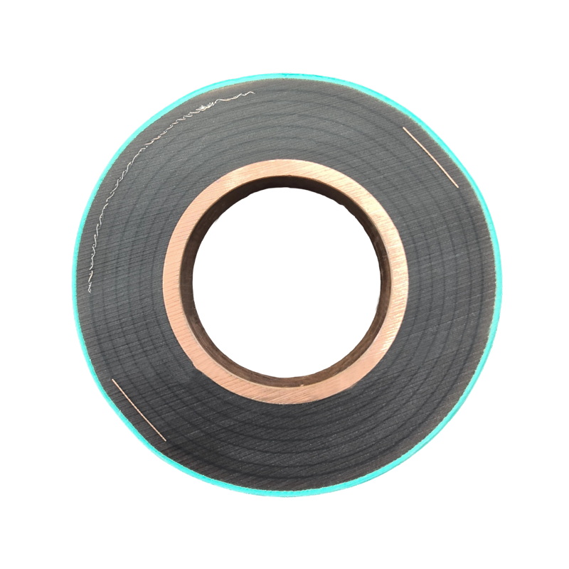
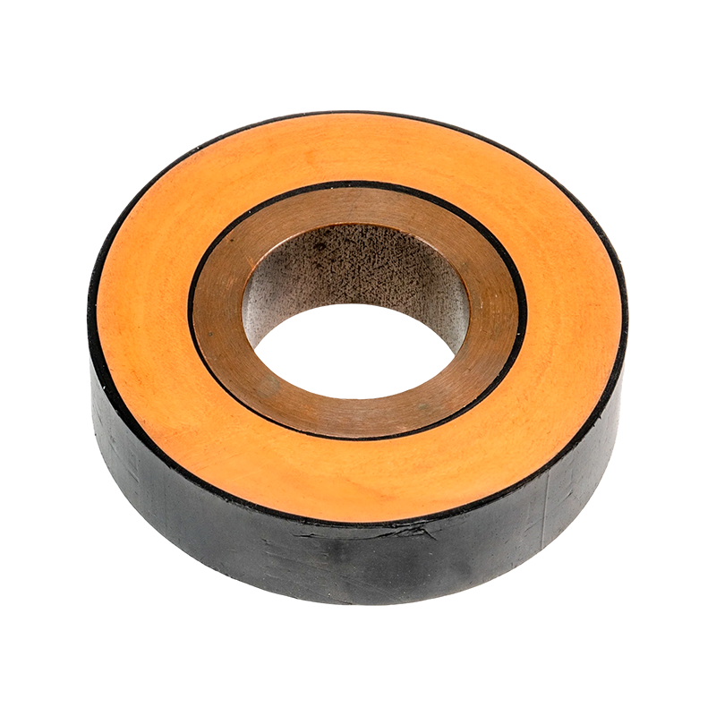
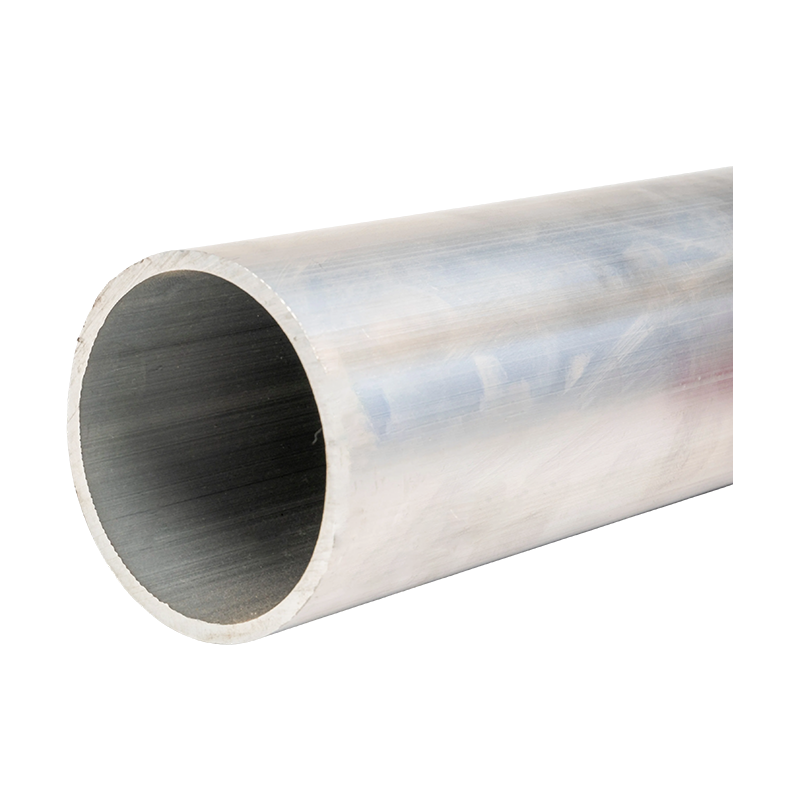
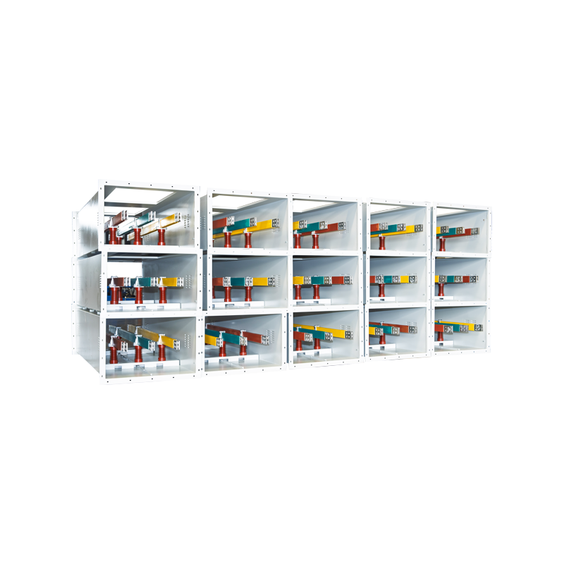

Advanced Power Busway Systems for High-Current Industrial and Commercial Distribution
Content
- 1 1. What Is a Power Busway?
- 2 2. Product Design and Construction
- 3 3. Main Technical Advantages
- 4 4. Comparison with Traditional Cable Distribution
- 5 5. Modular Installation and Tap-Off Flexibility
- 6 6. Manufacturing Process and Engineering Strengths
- 7 7. Company Capabilities and Product Portfolio
- 8 8. Smart Monitoring and Preventive Maintenance
- 9 9. Applications in Industrial and Commercial Facilities
- 10 10. Product Selection Considerations
- 11 11. Installation and Commissioning Guidance
- 12 12. Maintenance and Serviceability
- 13 13. Competitive Advantages of the System
- 14 14. Frequently Asked Questions
- 14.1 Q1: What is the difference between a busbar and a power busway?
- 14.2 Q2: Is a power busway safer than traditional cables?
- 14.3 Q3: Can new equipment be added to an existing busway?
- 14.4 Q4: Which is better: copper or aluminum conductors?
- 14.5 Q5: What protection ratings are available?
- 14.6 Q6: How much installation time can a busway save?
- 14.7 Q7: Can the system be used outdoors?
- 14.8 Q8: What temperature range can the system withstand?
- 14.9 Q9: What testing is performed before delivery?
- 14.10 Q10: Is smart monitoring necessary for every busway installation?
- 14.11 Q11: How should a busway be maintained?
- 14.12 Q12: Can the manufacturer provide customized OEM solutions?
- 15 15. Conclusion
- 16 References
- 17 Product: Power Busway
Modern electrical infrastructure requires more than simply moving electricity from one point to another. Industrial plants, commercial buildings, data centers, renewable energy facilities, transportation systems, and large utility projects all depend on distribution equipment that can carry substantial current safely, efficiently, and reliably. As electrical loads continue to increase, traditional cable-based systems may become difficult to install, expensive to maintain, and inflexible when facilities expand or equipment layouts change. A power busway provides a structured alternative by combining high-capacity conductors, insulation, protective housing, modular connections, and engineered accessories into one integrated distribution system.
The Power Busway described in this article is designed for high-current power transmission and distribution. It uses high-purity electrolytic copper or premium aluminum alloy conductors, optimized conductor geometry, fully insulated construction, and a strong protective enclosure. Depending on the selected configuration, the system can support current ratings from approximately 250 A to 6300 A and can be customized for medium- and low-voltage applications. Its design emphasizes low impedance, reduced voltage drop, heat dissipation, short-circuit withstand capability, environmental protection, installation efficiency, and long-term serviceability.
Manufactured by Jiangsu Wopeng Power Technology Co., Ltd., the system is supported by engineering experience in high- and low-voltage busbar technology, vacuum casting, CNC machining, automated assembly, electrical testing, and quality control. The manufacturer’s product range includes epoxy resin vacuum-cast tubular busbars, low-voltage cast resin busways, copper and aluminum tubular busbars, wind power tubular busbars, compact busbar systems, and sliding contact line systems. This broad technical foundation enables the company to provide engineered solutions for demanding power distribution environments rather than relying on a single standardized product.
This article explains the construction, operating principles, technical advantages, manufacturing strengths, applications, selection criteria, and maintenance considerations of advanced power busway systems.

Power Busway
1. What Is a Power Busway?
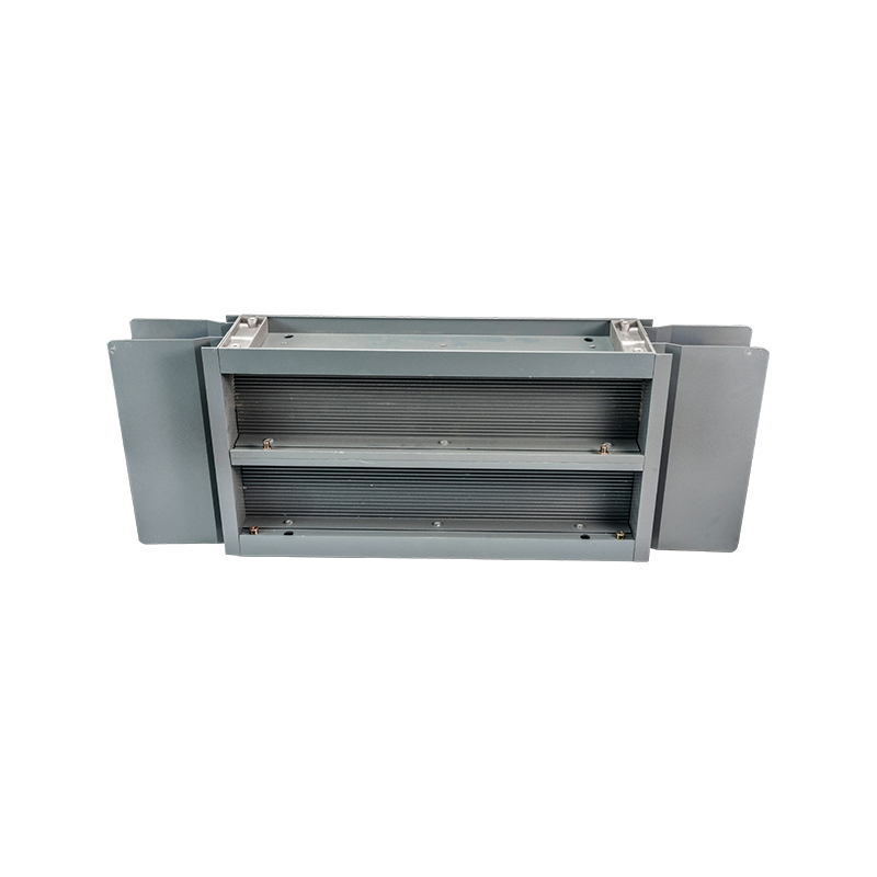
A power busway, also called a bus duct or busbar trunking system, is an enclosed electrical distribution assembly containing one or more insulated conductors. The conductors are normally made from copper or aluminum and are arranged inside a protective housing. The system transfers electrical power between transformers, switchgear, distribution panels, motor control centers, production equipment, and other downstream loads.
Unlike a conventional cable installation, a busway uses rigid, factory-engineered conductors assembled into standardized sections. These sections are joined together along a defined route. Depending on the design, tap-off units can be installed at selected locations, allowing power to be supplied to equipment without routing separate heavy cables from the main distribution board to every load.
The enclosure performs several functions. It protects the conductors from accidental contact, dust, moisture, impact, and mechanical damage. It also helps contain thermal energy, provides a grounding path when designed as part of the protective system, and creates a neat, organized distribution route. In harsh or sensitive environments, the enclosure and insulation system can be engineered to achieve higher ingress protection, including configurations reaching IP66.
Power busways are particularly valuable where high current must be transmitted over a relatively long distance or where future modifications are likely. Industrial workshops, assembly plants, data centers, logistics facilities, large commercial buildings, and renewable energy installations often benefit from the modular nature of busbar trunking.
2. Product Design and Construction
High-Purity Copper and Aluminum Conductors
The conductor is the electrical core of the busway. Copper is selected when high conductivity, compact dimensions, excellent connection performance, and strong thermal characteristics are required. Aluminum alloy is selected when lower weight, cost efficiency, and suitable mechanical performance are important. Both conductor materials can be engineered for high-current applications when the cross-sectional area, joint design, insulation, and thermal conditions are correctly matched.
The system uses high-purity electrolytic copper or premium aluminum alloy conductors. High-purity materials help reduce electrical resistance and support stable performance under continuous load. Material consistency is also important because variations in conductivity, hardness, or surface condition can affect joint reliability and temperature rise.
For aluminum conductors, appropriate surface treatment and connection design are essential. Aluminum naturally forms an oxide layer that can influence electrical contact quality. Professional manufacturing processes address this issue through controlled machining, surface preparation, joint engineering, and suitable connection hardware. These details distinguish a professionally engineered aluminum busway from a low-cost assembly with uncertain long-term performance.
Optimized Conductor Geometry
At high current, alternating current does not distribute evenly throughout the entire conductor cross-section. Skin effect and proximity effect can increase effective resistance and create additional losses. The Power Busway addresses these issues through specially shaped conductors and carefully arranged phase positions.
Conductor geometry can be optimized to improve the distribution of current, increase heat-transfer surface area, and reduce unnecessary impedance. Symmetrical three-phase arrangements help balance the magnetic field and support more uniform current distribution. These design choices are especially significant in high-current systems, where small improvements in impedance and temperature rise can produce meaningful energy savings over the service life of the installation.
Fully Insulated Encapsulation
The conductors are separated and protected by a fully insulated structure. Insulation prevents phase-to-phase contact, reduces the risk of accidental electric shock, and supports stable dielectric performance. In cast resin or encapsulated designs, insulation can also improve resistance to moisture, dust, chemicals, vibration, and mechanical stress.
Insulating materials for the system are selected to provide strong electrical and thermal performance. Materials complying with UL94 V-0 fire-resistance requirements are self-extinguishing and help limit the spread of flame. The specific insulation system, voltage rating, temperature class, and test requirements should be confirmed according to the project specification.
Protective Housing
The external housing provides mechanical protection and environmental resistance. A heavy-duty aluminum alloy enclosure offers a useful combination of strength, corrosion resistance, low weight, and heat dissipation. The housing can also serve as part of the grounding and equipotential bonding arrangement when properly designed and connected.
Standard systems can be supplied with protection ratings such as IP54, while specially configured designs can reach IP65 or IP66. The correct rating depends on joint construction, covers, sealing materials, tap-off arrangements, installation orientation, and the environmental conditions at the project site. A high protection rating is particularly important in dusty factories, humid facilities, outdoor areas, washdown zones, and locations where water exposure is possible.
3. Main Technical Advantages
High Current-Carrying Capacity
The system is designed for a broad current range. Depending on the product configuration, applications may require ratings from 250 A for smaller distribution branches to 6300 A or more for major feeder routes. This range allows the same overall busway concept to be applied across different sections of a facility, from transformer outputs and main switchgear connections to production-line branches and equipment distribution.
High current capacity is achieved through the combined effect of conductor material, cross-sectional area, conductor arrangement, insulation system, enclosure design, joint quality, and thermal management. It is not determined by conductor size alone. A properly engineered busway maintains acceptable temperature rise and voltage drop while operating under the specified load and ambient conditions.
Low Impedance and Reduced Voltage Drop
Low impedance is one of the most important performance characteristics of a high-current distribution system. Excessive impedance causes voltage drop, heat generation, energy loss, and reduced equipment performance. The Power Busway uses optimized conductor profiles, short and reliable joints, symmetrical phase arrangement, and carefully designed housing components to minimize impedance.
For suitable system configurations and installation conditions, voltage drop can be controlled below 1 percent. The actual result depends on current, route length, conductor material, ambient temperature, joint quantity, power factor, and system design. Low voltage drop is especially valuable for large motors, variable-speed drives, welding equipment, data center loads, and other applications with high starting or transient currents.
Compared with long parallel cable runs, a busway can provide a more compact and orderly conductor arrangement. It can also reduce the number of individual terminations and simplify route planning. These advantages may help reduce resistive losses and improve overall distribution efficiency.
Short-Circuit Withstand Capability
Power distribution equipment must withstand the mechanical and thermal forces produced by fault currents until protective devices disconnect the fault. The busway is designed to resist short-circuit current impacts in the range of approximately 50 kA to 100 kA for one second, depending on the selected model and tested configuration.
Short-circuit performance depends on conductor support, insulation strength, joint structure, enclosure rigidity, and the effectiveness of the protective device coordination. High-strength internal supports prevent conductors from moving excessively under electromagnetic forces. A robust enclosure protects the assembly and contributes to the mechanical stability of the complete system.
Project engineers should select the short-circuit rating based on the available fault current at the installation point. The specified withstand rating must be coordinated with transformer capacity, upstream circuit breakers, protective relay settings, and the required fault-clearing time.
Strong Insulation Performance
The insulation system is designed to support high electrical stress. Representative performance values include a power-frequency withstand voltage of approximately 3500 V for one minute and an impulse withstand voltage of approximately 8000 V, subject to the applicable product design and test standard.
High insulation performance improves operational reliability and reduces the likelihood of flashover, tracking, and insulation breakdown. It is particularly important in systems exposed to humidity, industrial contamination, switching surges, or frequent load changes. Factory testing provides greater control over insulation quality than field-built cable assemblies, where installation workmanship can vary significantly.
Fire Resistance
Fire safety is a major consideration in electrical distribution. Insulating materials that meet UL94 V-0 requirements are designed to self-extinguish after the removal of an ignition source. This characteristic helps limit flame propagation within the system.
Fire resistance does not eliminate the need for correct system protection, cable compartment design, fire stopping, or building fire controls. However, it adds an important layer of safety. A fully enclosed busway also reduces the possibility that combustible dust or foreign objects will come into direct contact with energized conductors.
Moisture and Corrosion Resistance
The enclosed structure protects the conductors from many environmental hazards. Sealed joints, covers, insulation, and an appropriately rated housing can help prevent water and dust from reaching live components. This makes the system suitable for a wide range of industrial environments.
For corrosive or humid locations, material selection and surface treatment must be matched to the site. Aluminum alloy housing can provide good corrosion resistance, while additional coatings, stainless steel hardware, special seals, or enhanced encapsulation may be selected for more aggressive atmospheres. The final specification should consider chemicals, salt exposure, condensation, cleaning methods, and outdoor installation conditions.
Seismic and Mechanical Strength
Electrical distribution systems installed in seismic regions must remain stable during movement and vibration. The busway structure is designed to withstand seismic intensity up to level 8 when the appropriate supports, joints, anchoring, and installation methods are used.
Mechanical performance depends on the complete installation rather than the busway alone. Hangers, brackets, expansion sections, building interfaces, and connection points must all be designed in accordance with the project’s seismic requirements. The rigid modular form of a busway can simplify route control, but it must be supported correctly to avoid excessive stress at joints.
4. Comparison with Traditional Cable Distribution
Traditional cable systems remain useful for many electrical applications, but high-current installations can become complicated. Large cable routes require substantial space, heavy support structures, multiple parallel runs, numerous bends, and many terminations. Cable pulling may require specialized labor and significant preparation, especially when the route is long or difficult to access.
A busway is factory-engineered in standard sections. Its compact profile can reduce the space required for power distribution routes. Straight sections, elbows, flanges, expansion units, end feeds, and tap-off boxes can be combined to follow the building layout. This approach provides a cleaner route and can reduce installation uncertainty.
Busway sections are also easier to modify in many facilities. A new tap-off unit can be installed at an approved plug-in location, allowing a branch circuit to be added without pulling a new set of heavy cables across the facility. This is a major advantage for factories where machinery layouts change or production capacity expands.
Installation efficiency can be more than 50 percent higher than traditional cable installation in suitable projects. The actual result depends on route complexity, labor availability, access conditions, system voltage, and the number of branch connections. Even where the time saving is lower, the reduction in cable handling, termination work, and route congestion can provide significant practical value.
| Criteria | Power Busway | Traditional Cable System |
|---|---|---|
| High-current transmission | Well suited to organized feeder routes from approximately 250 A to 6300 A or more, depending on configuration | May require multiple parallel cables and larger support systems |
| Installation method | Factory-made modular sections with standardized joints | Field cutting, pulling, routing, and termination |
| Future expansion | Tap-off units and reserved interfaces can support additional loads | Often requires new cable routes and additional trays or conduits |
| Space utilization | Compact and orderly route with a defined enclosure | Multiple cables may require broad trays and greater clearance |
| Voltage drop | Low impedance design can support voltage drop below 1 percent in suitable configurations | Depends heavily on cable length, conductor size, parallel arrangement, and termination quality |
| Maintenance | Accessible covers, joints, and modular sections simplify inspection | Fault finding may involve tracing and testing individual cables |
| Environmental protection | Enclosures can provide IP54 to IP66 protection depending on design | Protection depends on cable insulation, tray design, conduit, glands, and environmental sealing |
| Layout flexibility | Tap-off points allow relatively fast connection changes | Changes may require cable replacement or additional wiring |
| Factory quality control | Sections and joints are manufactured and tested under controlled conditions | Final installation quality depends substantially on field workmanship |
The comparison does not mean that busway is automatically the best option for every circuit. Small isolated loads, highly flexible mobile equipment, outdoor temporary installations, and irregular routes may still be better served by cables. However, for high-current, fixed, expandable, and organized distribution, busway often provides a stronger long-term solution.
5. Modular Installation and Tap-Off Flexibility
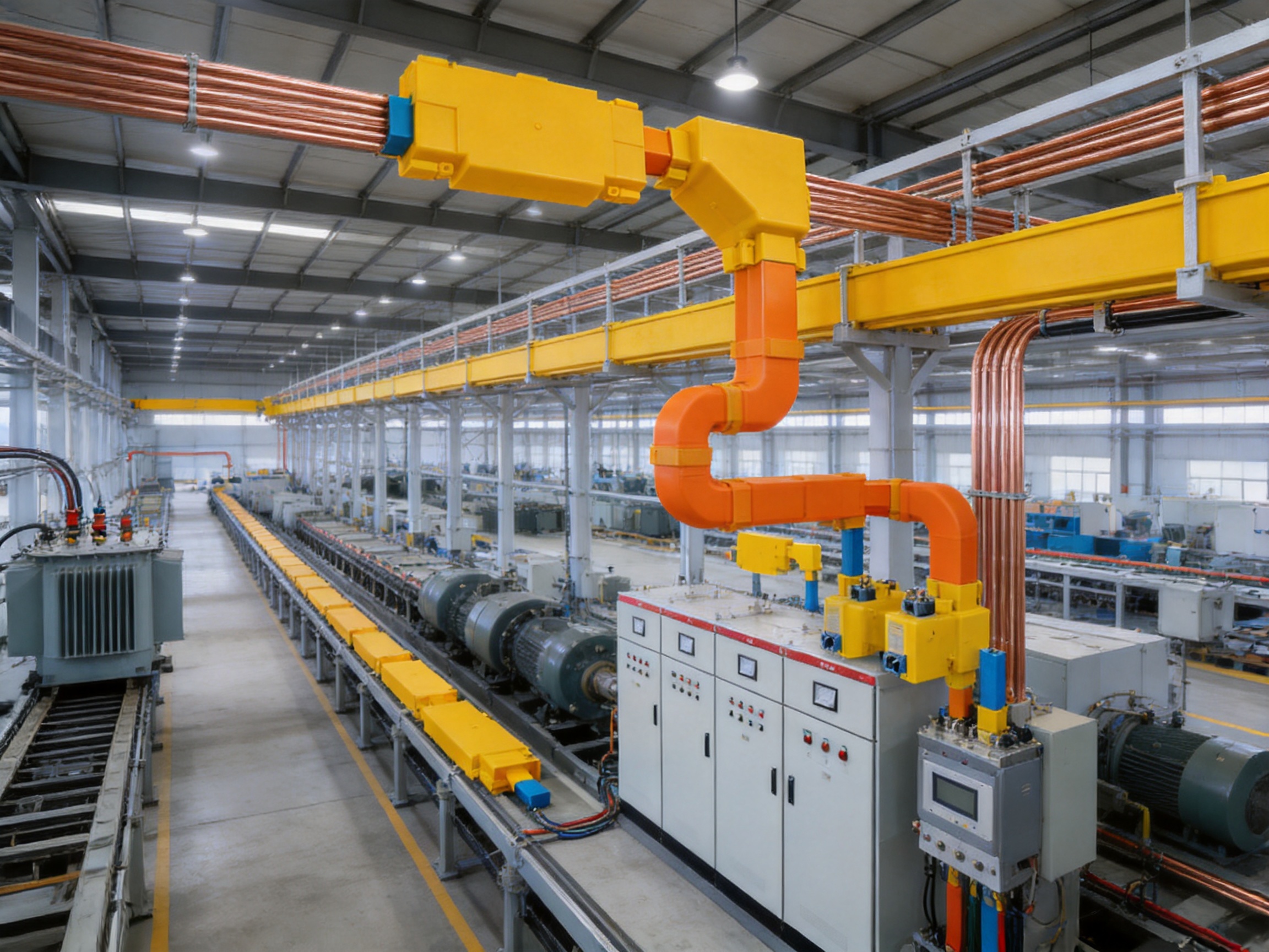
A central advantage of a busway system is its modular architecture. Standard-length sections can be manufactured, transported, positioned, and connected in sequence. Special sections can be produced for bends, changes in elevation, equipment interfaces, and building penetrations.
Tap-off units allow power to be taken from the busway at selected points. These units may feed motor control centers, distribution panels, machinery, charging equipment, lighting systems, or other loads. When the busway is designed with suitable plug-in interfaces, new connections can be added more quickly than with a conventional cable installation.
Tap-off equipment must be selected for the system voltage, current, fault level, enclosure rating, protective device requirements, and connection orientation. The plug-in unit must be installed according to the manufacturer’s instructions, and any interlocking or safety mechanism must be verified before energization.
Modularity also improves project planning. The main busway route can be installed before all downstream equipment is fully positioned. As the production line or building fit-out develops, additional tap-off units can be added at designated locations. This helps reduce the need for major electrical rework during future expansion.
The system may include removable cover plates that facilitate inspection and maintenance. In a properly isolated and de-energized condition, technicians can access joints, connection points, and protective components more easily than they could in a densely packed cable tray.
6. Manufacturing Process and Engineering Strengths
Engineering-Based Product Development
Reliable busway performance begins with engineering. Electrical, mechanical, thermal, insulation, and installation factors must be evaluated together. The manufacturer’s experience across high- and low-voltage busbar systems provides a foundation for developing products for different current ratings, voltage levels, environmental conditions, and installation arrangements.
Engineering work includes conductor sizing, electromagnetic analysis, temperature-rise evaluation, insulation coordination, short-circuit mechanical analysis, enclosure design, joint development, and accessory compatibility. The result is not merely a metal enclosure containing conductors; it is a coordinated power transmission system.
Vacuum Casting and Encapsulation
Vacuum casting is used in the production of epoxy resin vacuum-cast tubular busbars and other insulated busbar products. Under controlled conditions, resin is introduced around the conductor and insulating structure while air and voids are minimized. Reducing voids helps improve dielectric consistency and resistance to partial discharge, moisture penetration, and mechanical stress.
Vacuum-cast insulation can create a solid, compact structure with high mechanical strength. It is particularly useful for medium-voltage and harsh-environment applications where the insulation must withstand electrical stress and environmental exposure. Process control is essential because resin mixing, temperature, vacuum level, curing time, and mold condition all influence the final result.
Although the Power Busway product family may include several insulation technologies depending on voltage and application, the manufacturer’s vacuum casting capability demonstrates a strong understanding of encapsulated electrical insulation and high-reliability busbar construction.
CNC Machining
CNC machining supports precision production of conductor components, joint parts, enclosure interfaces, mounting pieces, and specialized accessories. Accurate machining helps control dimensional tolerances and ensures that sections fit together correctly during installation.
Precision is particularly important at conductor joints. A joint that is misaligned, unevenly tightened, poorly finished, or contaminated can create localized resistance and excessive heating. CNC processing, combined with controlled assembly procedures, helps achieve repeatable joint quality.
Automated Assembly
Automated and standardized assembly technologies improve consistency across production batches. They help control conductor positioning, insulation placement, enclosure alignment, fastening, and accessory installation. Automation does not replace engineering judgment or inspection, but it can reduce variation and improve production efficiency.
For modular busway systems, repeatability is essential. Each straight section, elbow, joint, and tap-off interface must conform to the same design requirements so that the complete route can be assembled reliably at the project site.
Strict Inspection and Testing
Every electrical distribution product should be supported by systematic inspection. The manufacturing process includes standardized checks such as high-voltage testing, insulation testing, mechanical verification, dimensional inspection, and routine quality checks.
High-voltage tests verify that the insulation system can withstand specified electrical stress. Insulation resistance testing provides information about the condition of the insulating materials and assembly. Mechanical verification confirms that housings, supports, joints, and mounting features meet the required structural conditions.
Testing collaboration with third-party institutions provides an additional level of independent validation. Independent testing can support confidence in safety and performance claims, especially when products are supplied for critical infrastructure or exported to markets with strict technical requirements.
Quality Management and Traceability
A strong quality system should control incoming materials, production parameters, in-process inspection, final assembly, test records, packaging, and shipment. Material certificates, conductor dimensions, resin batch information, test results, and inspection documentation can support traceability throughout the product lifecycle.
Quality management is particularly important for custom products. A busway route may include nonstandard lengths, multiple bends, special tap-off locations, higher enclosure protection, or unusual installation conditions. Controlled documentation ensures that the manufactured product matches the approved design.
7. Company Capabilities and Product Portfolio
Jiangsu Wopeng Power Technology Co., Ltd. was founded in 2018 as a specialized high-tech enterprise focused on the development and manufacture of high- and low-voltage busbar systems. The company combines engineering personnel, technical specialists, production professionals, modern manufacturing equipment, and standardized inspection procedures.
Its product portfolio covers electrical distribution requirements from low voltage to 35 kV. Products include 35 kV epoxy resin vacuum-cast tubular busbars, low-voltage epoxy-cast busbar trunking, copper and aluminum tubular busbars, tubular busbars for wind turbines, compact busbar systems, and sliding contact line power supply systems.
This breadth is valuable for customers with multiple electrical requirements. A project may need a medium-voltage connection between a transformer and a distribution system, a low-voltage busway for workshop equipment, and a specialized tubular busbar for a renewable energy installation. A manufacturer with experience in several product categories can coordinate technical requirements more effectively than a supplier focused on only one narrow product type.
The company’s products operate across more than 17 provinces and key industrial sectors. Applications include power generation, substations, wind energy, industrial manufacturing, rail transit, large commercial facilities, and other critical infrastructure. Such field exposure helps develop practical knowledge of installation conditions, environmental challenges, maintenance expectations, and customer-specific requirements.
The manufacturer also provides OEM-oriented support. Customized solutions may include conductor material, current rating, voltage class, enclosure protection, insulation type, route geometry, connection arrangement, tap-off locations, mounting method, and monitoring options. Customization is most effective when supported by clear technical drawings, load data, route measurements, environmental information, and applicable project standards.
8. Smart Monitoring and Preventive Maintenance
Electrical failures often develop gradually. Rising joint temperature, moisture, loose connections, insulation deterioration, and abnormal loading may remain unnoticed until they cause a trip or outage. An integrated monitoring system can provide early information about important operating conditions.
Depending on the selected configuration, smart monitoring can track temperature, humidity, and connection status. Temperature monitoring is particularly useful at joints, tap-off points, and areas with high current density. A gradual temperature increase may indicate loose hardware, unbalanced loading, excessive ambient temperature, or a deteriorating connection.
Humidity monitoring can help identify condensation risks in environments with large temperature changes. Connection-status monitoring can support maintenance teams by showing whether access covers, tap-off units, or other components are correctly positioned and secured.
Monitoring does not replace electrical protection or periodic inspection. Instead, it provides additional information for preventive maintenance. Data can be integrated into a facility management system or reviewed through a local monitoring interface, depending on project requirements.
Preventive maintenance can reduce unexpected downtime. Maintenance personnel may schedule inspections when operating conditions show a developing trend rather than waiting for a failure. For data centers, production facilities, and process plants, this approach can have substantial economic value.
9. Applications in Industrial and Commercial Facilities
Manufacturing Plants
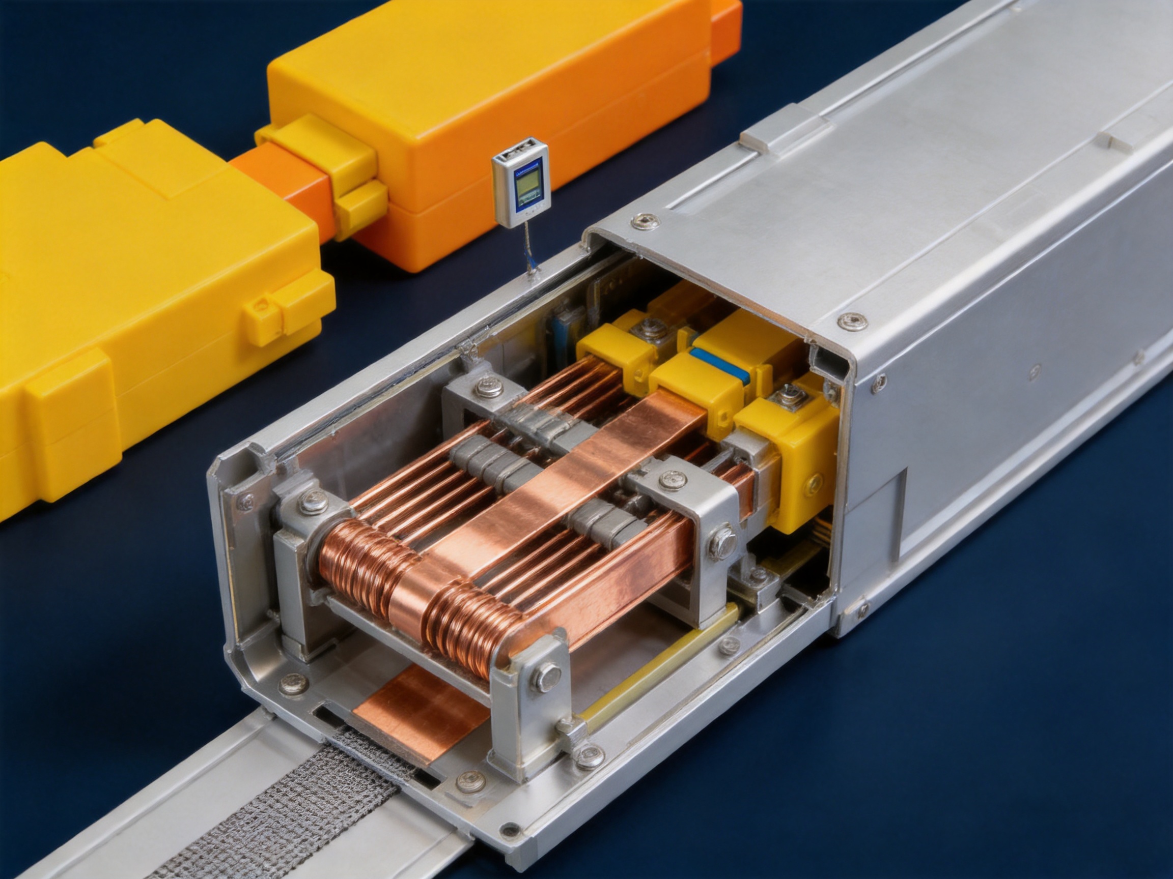
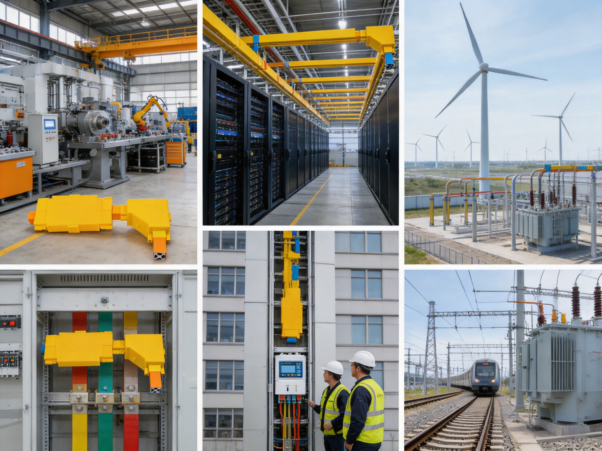
Manufacturing plants often contain motors, welding machines, compressors, furnaces, conveyors, robotic systems, and process equipment. These loads may be distributed across a large workshop and may change as production lines are reorganized.
A high-current busway can carry power from the main transformer or switchgear along the production area. Tap-off units can supply individual machine groups or local distribution panels. The modular route is easier to extend than a fixed network of large cables, making it suitable for plants with future capacity requirements.
Data Centers
Data centers require reliable and organized power distribution for servers, storage systems, cooling equipment, network infrastructure, and backup systems. Space is valuable, and maintenance access must be carefully controlled.
Busway can provide a compact distribution route and support flexible connection points. Its enclosed construction helps protect conductors, while monitoring options can provide additional information about temperature and connection conditions. In redundant power architectures, separate busway routes can be used for independent power paths.
Data center designers must consider availability, selective coordination, fault levels, thermal management, electromagnetic compatibility, grounding, and maintenance bypass requirements. The busway should be integrated into the overall critical-power design rather than selected as an isolated component.
Commercial Buildings
Large commercial buildings, shopping centers, hospitals, airports, and office complexes may require high-capacity vertical and horizontal distribution. A busway can be installed in electrical risers or service corridors to supply floor distribution boards and major mechanical equipment.
The compact form of busway helps reduce congestion in building services areas. Plug-in units can support floor-by-floor distribution, while standard sections simplify coordination between electrical contractors and other building trades.
Renewable Energy Projects
Wind power, solar power, energy storage, and other renewable energy projects require specialized electrical connections. Tubular busbars and insulated busway systems can be used in generator, inverter, transformer, collection, and auxiliary power applications, subject to the voltage and environmental conditions of the project.
Wind turbines present particular challenges, including vibration, restricted installation space, temperature variation, and maintenance difficulty. Tubular busbars designed for wind power can provide a compact alternative to large cable bundles when the system is correctly engineered for movement and operating conditions.
Rail Transit and Transportation
Rail transit facilities include traction substations, depots, workshops, stations, signaling systems, and maintenance buildings. Reliable distribution is essential because electrical interruptions may affect safety, schedules, and facility operations.
Busway systems can be used in suitable fixed distribution areas where high current, compact routing, and controlled maintenance are required. The exact product must be selected according to the voltage, grounding method, environmental exposure, fire requirements, and applicable transportation standards.
Power Generation and Substations
Power plants and substations use busbar systems to connect generators, transformers, switchgear, auxiliary systems, and distribution equipment. Medium-voltage tubular busbars and cast resin busbars can provide insulated, compact connections in locations where air-insulated arrangements or cable systems are less suitable.
Substation applications place significant demands on insulation coordination, short-circuit performance, mechanical strength, environmental resistance, and inspection documentation. Engineering review and testing are therefore essential before final selection.
10. Product Selection Considerations
Selecting the correct busway requires more than choosing a current rating. The following factors should be evaluated during the design stage.
Rated Current
The rated current should be based on continuous load, demand factor, future expansion, ambient temperature, installation method, and applicable derating requirements. A system that is too small may operate at excessive temperature, while an unnecessarily oversized system may increase project cost and physical dimensions.
Voltage and Insulation Level
The voltage class determines the insulation system, clearances, creepage distances, test requirements, and accessory design. Low-voltage busway and medium-voltage tubular busbar systems should not be treated as interchangeable products.
Short-Circuit Current
The available short-circuit current at the installation point must be calculated or obtained from the power system study. The busway short-time withstand rating and peak withstand rating should be compatible with the fault level and protective device operating time.
Environmental Conditions
Designers should identify indoor or outdoor installation, ambient temperature, humidity, condensation, dust, water exposure, chemical contamination, salt spray, vibration, seismic conditions, and altitude. These factors influence the required enclosure rating, insulation type, housing material, sealing system, and support arrangement.
Route Geometry
Accurate route information is necessary for producing straight sections, elbows, offsets, expansion units, end feeds, and equipment interfaces. A coordinated three-dimensional route survey can reduce installation problems and avoid field modifications that may compromise enclosure protection or joint quality.
Expansion and Tap-Off Requirements
The number and location of present and future connections should be considered before manufacturing. Reserved plug-in interfaces can provide valuable flexibility, but they should be positioned where equipment can be safely accessed and maintained.
Monitoring Requirements
Critical facilities may benefit from temperature, humidity, and connection monitoring. Monitoring requirements should be defined together with communication protocols, alarm thresholds, data storage, and integration with the building or industrial management system.
11. Installation and Commissioning Guidance
Installation should be performed by qualified personnel using approved drawings and procedures. Before assembly, each section should be checked for transport damage, correct identification, dimensional accuracy, and compatibility with the installation route.
Supports must be installed at the specified spacing and designed for the weight, mechanical forces, seismic requirements, and expansion conditions of the system. The busway should not be forced into alignment by excessive mechanical stress. Misalignment can affect joints, covers, seals, and conductor connections.
Joints should be clean, correctly positioned, and tightened according to the specified torque values. Over-tightening can damage components, while under-tightening can increase contact resistance. After assembly, protective covers, barriers, seals, grounding connections, and tap-off interlocks should be checked.
Commissioning typically includes visual inspection, continuity checks, insulation resistance tests, phase identification, protective conductor verification, high-voltage testing where required, and functional testing of tap-off and monitoring equipment. Test results should be recorded for future reference.
The system should not be energized until all covers are installed, unused openings are sealed, protective devices are configured, and the installation has passed the required inspection. Safety procedures must include isolation, lockout, verification of absence of voltage, and appropriate personal protective equipment.
12. Maintenance and Serviceability
A maintenance program should be established according to the operating environment and criticality of the installation. Routine inspections may include checking enclosure condition, support hardware, joint temperature, signs of corrosion, water ingress, unusual noise, odor, vibration, and changes in monitoring data.
Thermal scanning can identify abnormal heating at joints and tap-off units. If a hot spot is detected, the equipment should be investigated under a controlled maintenance procedure. Possible causes include loose connections, overload, phase imbalance, contamination, damaged insulation, or inadequate ventilation.
Insulation testing and electrical verification should be performed at intervals appropriate to the voltage level and operating conditions. Testing frequency may be increased in humid, dusty, corrosive, or high-temperature locations.
Modular sections and removable covers can simplify service work. However, maintenance must always be performed with the system safely isolated unless a specific energized-work procedure is authorized by the responsible electrical safety organization. Busway systems carry high fault energy, and visual accessibility does not remove the risk of arc flash or electric shock.
Replacement components should match the original system rating and design. Mixing incompatible joints, tap-off units, covers, or accessories can reduce protection performance and invalidate testing assumptions.
13. Competitive Advantages of the System
The Power Busway offers several advantages compared with conventional distribution approaches and less specialized busbar products.
First, it combines high-current capability with compact modular construction. The wide current range allows the system to serve major feeders and branch distribution requirements within a coordinated product family.
Second, the low-impedance design supports reduced voltage drop and lower power loss. Specially shaped copper or aluminum conductors and symmetrical phase arrangement improve electrical performance, especially under heavy load.
Third, the fully enclosed and insulated structure provides a higher level of protection than exposed busbars. Depending on the design, the system can achieve IP54 to IP66 protection and resist dust, moisture, mechanical impact, and accidental contact.
Fourth, the short-circuit withstand capability and robust enclosure are suitable for demanding industrial power systems. High fault withstand is essential for systems connected to large transformers or generators.
Fifth, modular installation and plug-in interfaces can reduce construction time by more than 50 percent compared with traditional cable installation in suitable projects. They also make future expansion more practical.
Sixth, the manufacturer’s capabilities extend beyond basic assembly. Vacuum casting, CNC machining, automated production, electrical testing, mechanical verification, and third-party testing collaboration provide a stronger foundation for consistent quality.
Finally, customization and OEM support allow the product to be adapted to project-specific requirements. Customers can request suitable conductor materials, current levels, voltage classes, enclosure ratings, route configurations, monitoring systems, and accessories rather than accepting a one-size-fits-all solution.
14. Frequently Asked Questions
Q1: What is the difference between a busbar and a power busway?
A busbar is usually a single conductive bar or tube used within switchgear, a panelboard, a substation, or another electrical assembly. A power busway is a complete distribution system containing one or more busbars, insulation, joints, protective housing, supports, and often tap-off units. The busway is designed to carry power over a route and distribute it at multiple points.
Q2: Is a power busway safer than traditional cables?
A properly designed and installed busway provides strong protection through insulation, enclosure, grounding, and controlled joints. It can reduce accidental contact and protect conductors from environmental hazards. However, safety depends on correct product selection, installation, protection coordination, maintenance, and compliance with electrical safety procedures. No electrical distribution system is safe if it is incorrectly installed or operated.
Q3: Can new equipment be added to an existing busway?
In many cases, yes. Plug-in busway systems can accept tap-off units at designated locations. The new connection must be compatible with the busway voltage, current, fault rating, enclosure rating, and protective device requirements. The available capacity of the existing route must also be verified before adding a new load.
Q4: Which is better: copper or aluminum conductors?
Neither material is universally better. Copper provides high conductivity and compact dimensions, while aluminum can reduce weight and material cost. The correct selection depends on current, route length, installation space, budget, thermal conditions, mechanical requirements, and connection design. A professionally engineered aluminum system can provide reliable performance when its joints and surfaces are correctly designed.
Q5: What protection ratings are available?
Standard configurations may provide IP54 protection, while specially designed systems can reach IP65 or IP66. The actual rating depends on the enclosure, joints, seals, covers, tap-off units, and installation conditions. The required rating should be selected according to dust, water, humidity, and environmental exposure.
Q6: How much installation time can a busway save?
In suitable high-current projects, installation efficiency may improve by more than 50 percent compared with pulling and terminating traditional heavy cables. The actual saving depends on route length, access, labor conditions, number of bends, number of tap-off points, and the complexity of the electrical system.
Q7: Can the system be used outdoors?
Outdoor use may be possible when the busway is manufactured with the correct enclosure, sealing, corrosion protection, insulation, temperature range, and support arrangement. Outdoor projects must also address ultraviolet exposure, rain, condensation, drainage, lightning protection, and temperature cycling.
Q8: What temperature range can the system withstand?
Representative operating conditions may range from approximately -25°C to +70°C, depending on the product configuration and installation environment. The actual allowable current may require derating at high ambient temperatures. Project engineers should confirm the precise temperature range and thermal performance for the selected model.
Q9: What testing is performed before delivery?
Typical inspection may include dimensional checks, visual inspection, insulation resistance testing, power-frequency withstand testing, mechanical verification, conductor continuity checks, and routine quality examinations. The specific tests depend on the voltage level, product type, customer specification, and applicable standards.
Q10: Is smart monitoring necessary for every busway installation?
Smart monitoring is not required for every application, but it can be valuable in critical facilities, high-load systems, unmanned areas, data centers, and installations where preventive maintenance is important. Monitoring provides additional information about temperature, humidity, and connection status, helping maintenance teams identify developing problems earlier.
Q11: How should a busway be maintained?
Maintenance should include visual inspection, checking of supports and joints, thermal monitoring, enclosure inspection, insulation testing, and verification of tap-off units. The maintenance interval should reflect the operating environment and system criticality. All work must follow isolation and electrical safety procedures.
Q12: Can the manufacturer provide customized OEM solutions?
Yes. Customized solutions can be developed for current rating, conductor material, voltage, enclosure protection, insulation technology, route geometry, tap-off locations, installation method, and monitoring requirements. Accurate load data, route drawings, environmental information, and applicable standards are needed to prepare a suitable design.
15. Conclusion
The Power Busway is a modern high-current distribution solution that combines efficient conductors, low impedance, strong insulation, modular construction, environmental protection, and reliable mechanical performance. It is suitable for industrial plants, commercial buildings, data centers, renewable energy facilities, transportation infrastructure, power generation sites, and other projects where safe and adaptable power transmission is essential.
Its advantages over conventional cable systems include compact routing, reduced installation effort, low voltage drop, simplified expansion, organized maintenance, and the ability to provide tap-off connections along the route. The system can support current ratings from smaller distribution levels to approximately 6300 A or more, depending on the design, while short-circuit withstand capability may reach 50–100 kA for one second in suitable configurations.
The manufacturer’s strengths are equally important. Engineering expertise, vacuum casting capability, CNC machining, automated assembly, standardized inspection, third-party testing collaboration, and experience across low-voltage to 35 kV busbar products provide a strong foundation for dependable electrical equipment. These capabilities support both standard products and customized OEM solutions.
For the best result, busway selection should be based on a complete evaluation of load current, voltage, fault level, route geometry, ambient conditions, protection rating, expansion plans, maintenance strategy, and applicable standards. When correctly specified, manufactured, installed, and maintained, an advanced power busway can deliver efficient power distribution, strong operational reliability, and long-term flexibility for modern infrastructure.
References
1. IEC 61439, Low-Voltage Switchgear and Controlgear Assemblies.
2. IEC 60529, Degrees of Protection Provided by Enclosures.
3. IEC 60865, Short-Circuit Currents: Calculation of Effects.
4. IEC 62271 Series, High-Voltage Switchgear and Controlgear.
5. UL 94, Tests for Flammability of Plastic Materials for Parts in Devices and Appliances.
6. IEEE electrical power distribution and short-circuit analysis practices.
7. General engineering principles for busbar trunking systems, electrical insulation, thermal design, and power distribution.
8. Manufacturer technical information for insulated busbar, tubular busbar, busway, and medium- and low-voltage distribution products.
Product: Power Busway



-
 +86-180 3625 3000
-
 admin@wpbusbar.com
-
 No. 8, Yanjin Road, Chengxi Industrial Park, Shanyang Town, Baoying County, Yangzhou City, Jiangsu Province, China
Copyright © Jiangsu Wopeng Power Technology Co., Ltd.
All Rights Reserved.
 Custom Insulated Bus Bar Manufacturer
Tubular Busbar System Factory
Custom Insulated Bus Bar Manufacturer
Tubular Busbar System Factory