

 EN
EN

 English
 русский
 Français
 Español
 عربى
عربى
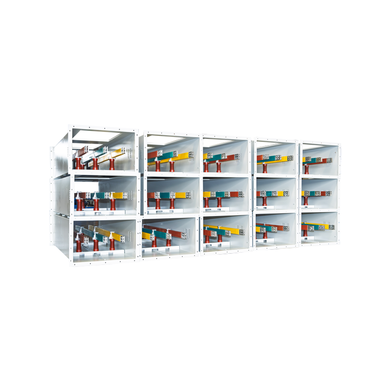


High-Density Compact Busway: A Reliable, Space-Efficient Solution for Modern Power Distribution
Content
- 1 1. Understanding High-Density Compact Busway
- 2 2. Construction and Operating Principle
- 3 3. Technical Specifications and Performance
- 4 4. Advantages Over Traditional Cable and Air-Insulated Systems
- 5 5. Applications in Modern Infrastructure
- 6 6. Manufacturing Process and Quality Control
- 7 7. The Manufacturer’s Engineering and Supply Strengths
- 8 8. Installation and Project Planning
- 9 9. Maintenance and Service Life
- 10 10. Selecting the Correct Compact Busway
- 11 11. Cost and Lifecycle Analysis
- 12 12. Frequently Asked Questions
- 12.1 Q1: What is a high-density compact busway?
- 12.2 Q2: What current range can the product support?
- 12.3 Q3: Is compact busway suitable for data centers?
- 12.4 Q4: Can compact busway replace all cable systems?
- 12.5 Q5: How does epoxy resin casting improve performance?
- 12.6 Q6: What does IP65 protection mean for the busway?
- 12.7 Q7: How often should the busway be maintained?
- 12.8 Q8: Can the busway be modified after installation?
- 12.9 Q9: What are the main advantages over traditional cable distribution?
- 12.10 Q10: What manufacturing technologies are used?
- 12.11 Q11: Can the manufacturer provide customized products?
- 12.12 Q12: What information should be provided when requesting a quotation?
- 13 13. Why Choose a Specialized Busbar Manufacturer?
- 14 14. Conclusion
- 15 References
- 16 Product: High-density Compact Busway
Modern buildings, industrial facilities, data centers, transportation projects, and renewable-energy installations require electrical distribution systems that can carry large currents safely while occupying as little space as possible. Traditional cable-based distribution can become difficult to install, maintain, and expand when power demand is high and available space is limited. High-density compact busway addresses these challenges by combining closely arranged conductors, robust insulation, modular construction, and high mechanical strength in a compact power distribution system.
High-density compact busway is a low-voltage cast-resin busway product designed for electrical distribution systems up to AC 400 V/690 V. The system uses copper conductors, epoxy resin casting technology, aluminum alloy enclosures, flame-retardant phase barriers, and plug-in connection technology. Together, these elements create a fully insulated, highly protected, and reliable method of transferring electrical power from a main distribution source to downstream equipment.
The product is particularly suitable for current ratings from 400 A to 5000 A and can be engineered for applications requiring high power density, low impedance, limited voltage drop, and rapid installation. Its compact structure allows more electrical capacity to be installed in a smaller area than many conventional cable and air-insulated bus duct arrangements. At the same time, its modular configuration supports future expansion and changes in load arrangement.
As a specialized manufacturer of high- and low-voltage busbar systems, Jiangsu Wopeng Power Technology Co., Ltd. combines product engineering, vacuum casting, precision machining, automated assembly, and standardized inspection procedures to provide customized busway solutions. The company’s experience across cast-resin busways, tubular busbars, compact busbar systems, and related electrical products enables it to address different project requirements from low-voltage distribution through medium- and high-voltage applications.
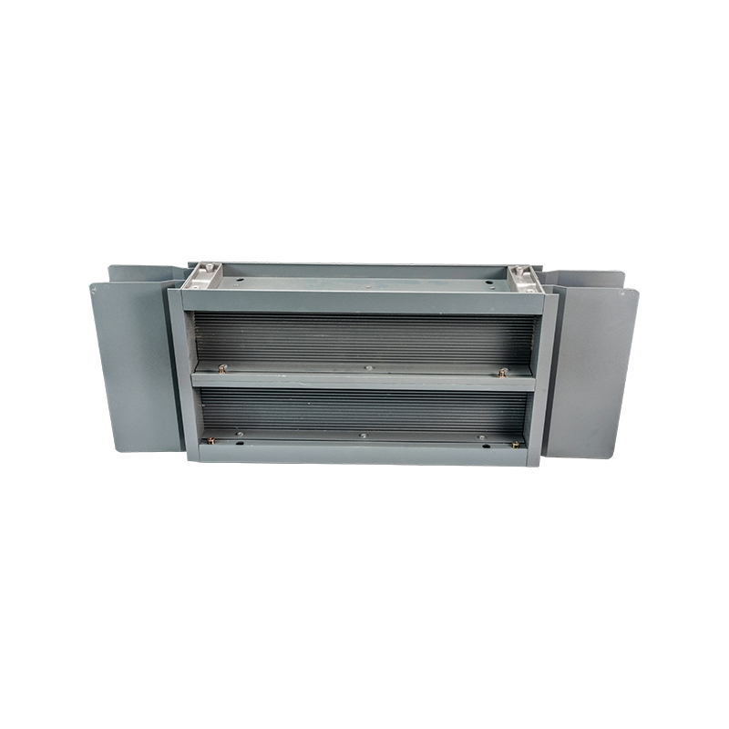
High-density Compact Busway
1. Understanding High-Density Compact Busway
A high-density compact busway is a prefabricated electrical distribution system in which conductive busbars are arranged closely inside a protective enclosure. Unlike separate power cables, which require individual insulation, support systems, bending space, and termination accessories, a busway integrates the conductors, insulation, housing, joints, and connection points into one coordinated assembly.
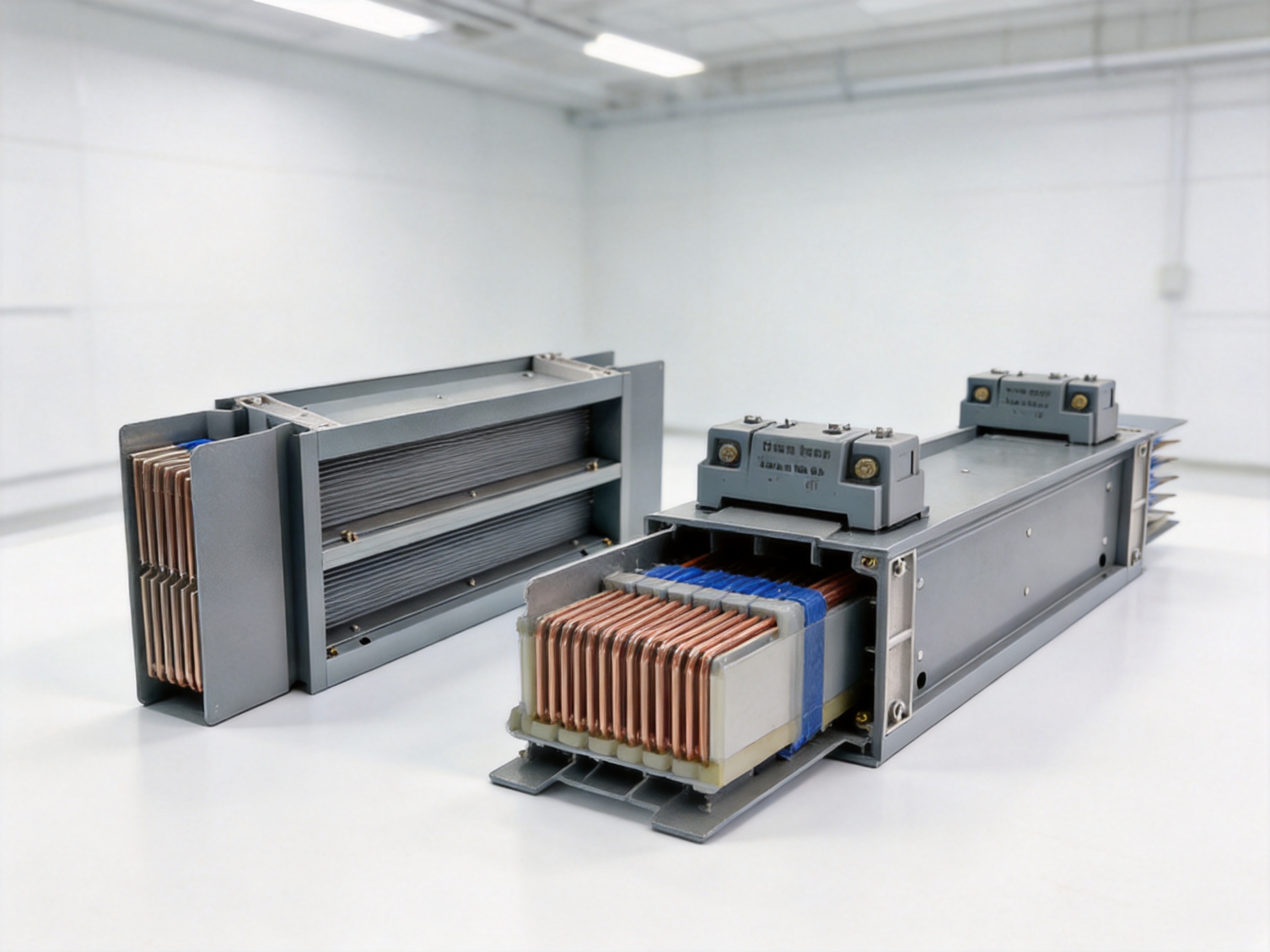
The central design principle is density. Copper conductors are positioned in a multilayer arrangement with carefully controlled spacing. The compact arrangement reduces the overall cross-sectional area of the distribution path while maintaining the required electrical clearances and insulation performance. This makes the system suitable for buildings and facilities where electrical shafts, ceiling spaces, plant rooms, or equipment corridors are restricted.
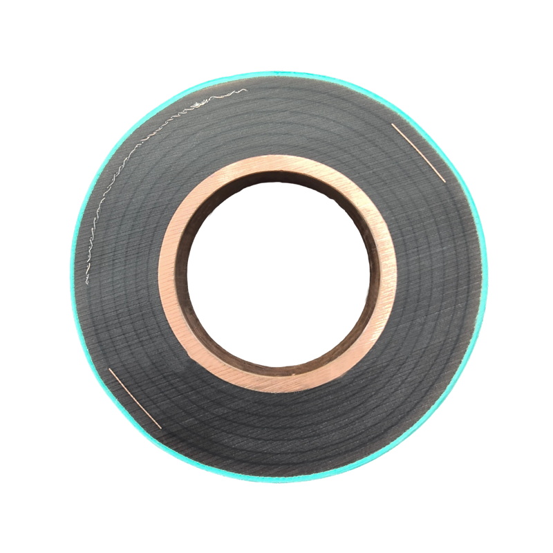
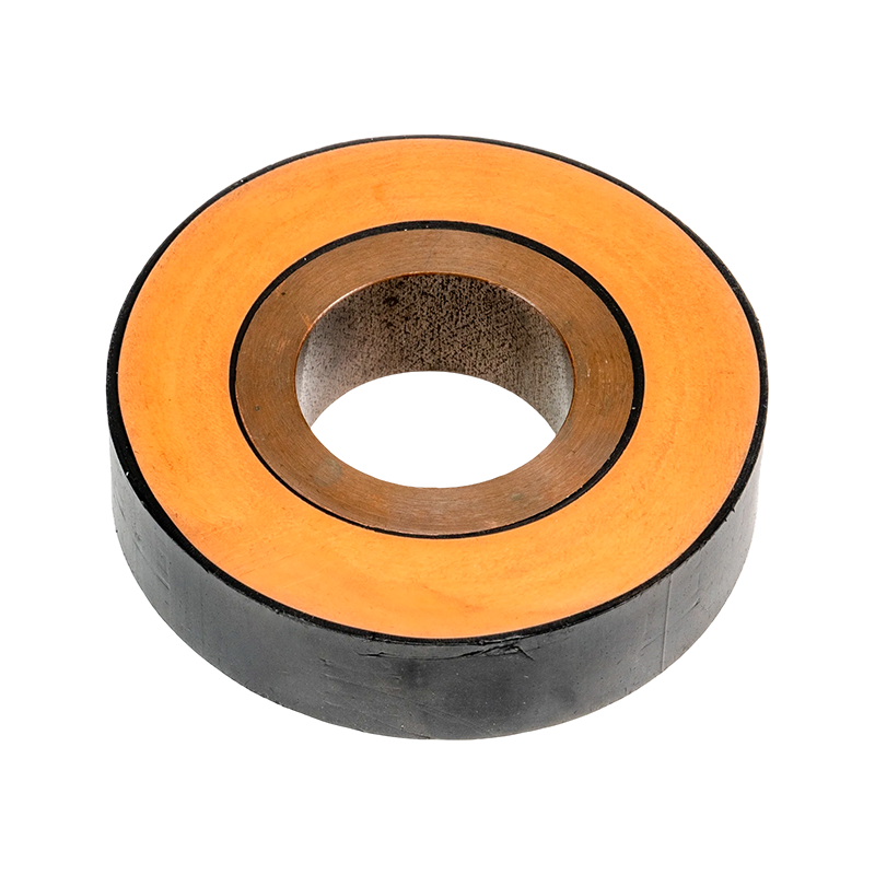
The conductors are encapsulated through integral epoxy resin vacuum casting. This process forms a continuous insulation system around the conductive components and helps eliminate internal voids that could otherwise weaken electrical performance. The cast-resin body also protects the conductors against dust, moisture, accidental contact, and mechanical impact.
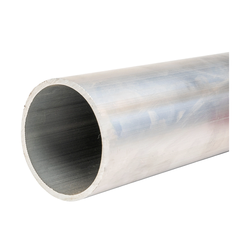
The enclosure is manufactured from high-strength aluminum alloy profiles. Aluminum provides a combination of low weight, corrosion resistance, mechanical strength, and effective heat dissipation. The enclosure also contributes to the overall structural stability of the busway and provides a practical housing for joints, plug-in units, and installation accessories.
Internal flame-retardant phase barriers maintain safe separation between phases. These barriers are important in a compact design because the conductors are positioned closer together than in many traditional air-insulated arrangements. By controlling the distance between live components and improving insulation coordination, the phase barriers contribute to short-circuit protection and operational safety.
The result is a factory-assembled distribution system that can be installed in straight sections, vertical risers, horizontal runs, and customized layouts. Depending on the project design, plug-in connection units can be positioned at regular intervals, allowing loads to be connected without installing long individual cable runs from the main distribution board.
1.1 Main Product Scope
The high-density compact busway is positioned within the low-voltage cast-resin busway category. It is designed for AC low-voltage distribution systems and can be configured according to rated current, route length, installation environment, connection method, and protection requirements.
Typical product parameters include a rated current range of 400 A to 5000 A, rated voltage of AC 400 V/690 V, insulation class F, and protection ratings up to IP65. The copper conductors are made from high-purity copper and may be tin-plated to improve connection reliability and resistance to oxidation.
The product can withstand a short-time current of 50 kA for one second, subject to the final engineering configuration and applicable test requirements. Its stated power-frequency withstand voltage is 3500 V per minute, while the temperature-rise limit is maintained below 70 K under specified operating conditions.
These parameters make the busway suitable for demanding low-voltage systems such as commercial buildings, industrial production areas, data centers, transportation facilities, utility buildings, and renewable-energy installations. Final selection should always be based on the complete electrical design, ambient conditions, installation method, fault level, and applicable standards.
2. Construction and Operating Principle
The performance of a compact busway depends on the coordinated design of several components rather than on the conductor alone. The copper bars, epoxy resin insulation, aluminum enclosure, phase barriers, joints, tap-off units, and support accessories must work as an integrated system.
2.1 High-Purity Copper Conductors
Copper is used as the primary conductor material because of its high electrical conductivity, mechanical strength, and established performance in power distribution systems. High-purity copper helps reduce resistance and power loss, particularly when large currents are transmitted over long routes or when the busway operates continuously near its design load.
The conductor arrangement is engineered to balance current capacity, electromagnetic behavior, thermal performance, and physical size. Multiple copper bars may be arranged in parallel or in a multilayer configuration to achieve the required rated current. Tin plating can be applied to the conductor surfaces and connection areas to improve contact stability and help protect against oxidation.
Reliable conductor joints are essential to busway performance. Connection points must provide sufficient contact pressure, low electrical resistance, mechanical stability, and resistance to loosening during thermal cycling or vibration. Precision machining and controlled assembly procedures help ensure consistency from one connection to another.
2.2 Epoxy Resin Vacuum Casting
Epoxy resin vacuum casting is one of the defining technologies of the product. During production, the conductors and insulation components are placed in a controlled casting arrangement. Resin is introduced under vacuum conditions so that the insulation material can fill the designed spaces and reduce the possibility of trapped air or internal voids.
A void-free or low-void insulation structure is important because internal air pockets may create localized electrical stress. Under high electrical stress, such defects can contribute to partial discharge, insulation deterioration, or long-term reliability problems. Vacuum casting helps create a solid insulating body with consistent dielectric properties.
The cured epoxy resin forms a rigid protective layer around the conductors. It provides electrical insulation and contributes to resistance against moisture, dust, chemical contamination, mechanical impact, and flame propagation. The resin system must be selected and processed according to the required temperature class, dielectric performance, mechanical properties, and environmental conditions.
Compared with loosely enclosed air-insulated products, cast-resin construction provides a more stable insulation geometry. The insulation does not depend solely on air clearances or on the condition of exposed insulating supports. This is especially beneficial in dusty, humid, vibration-prone, or space-constrained environments.
2.3 Aluminum Alloy Enclosure
The aluminum alloy enclosure protects the internal conductors and insulation system while supporting installation and heat dissipation. Aluminum is lighter than many steel alternatives, which can reduce handling difficulty and structural loading during installation. Its corrosion resistance also makes it appropriate for a range of indoor and semi-exposed environments when the enclosure and finish are correctly specified.
The enclosure provides mechanical protection against accidental contact and external impact. It also helps guide the busway along the intended route and supports connection accessories. In addition, the enclosure can participate in the thermal management of the system by transferring heat away from the internal conductor assembly.
The choice of aluminum alloy profile, wall thickness, surface treatment, and joint construction should be matched to the required mechanical and environmental conditions. Projects exposed to corrosive atmospheres, chemical vapors, high humidity, or outdoor weather may require additional enclosure protection and installation measures.
2.4 Flame-Retardant Phase Barriers
Phase barriers are installed between conductive phases to maintain safe electrical separation. In a densely arranged busway, the barriers help control the geometry of the insulation system and reduce the likelihood of phase-to-phase faults.
Flame-retardant materials are used to limit the spread of fire in the event of abnormal heating or an electrical fault. The stated fire-resistance performance meets the UL94 V-0 classification under the relevant test conditions. This classification indicates that the material is designed to stop burning within the prescribed test criteria, although the complete fire performance of an installed system depends on the entire assembly and project environment.
2.5 Plug-In Connection Units
Plug-in connection units provide a practical method of distributing power to downstream loads. Depending on the design, connection points may be arranged at intervals of approximately 500 mm to 1000 mm. This allows equipment such as distribution panels, motors, production lines, server racks, lighting systems, and mechanical services to be connected at suitable locations.
Plug-in units reduce the need for separate cable routes from the main switchboard to each individual load. They can also make changes to the distribution layout easier when the building or production process changes. Any addition, removal, or modification must be carried out by qualified personnel under an approved electrical safety procedure.
The plug-in system must be selected according to the required current, protective device, fault level, enclosure rating, connection direction, and equipment interface. Correct installation is essential to ensure that the contact surfaces are properly engaged and that the protective enclosure remains continuous.
3. Technical Specifications and Performance
The high-density compact busway is designed to meet the electrical and mechanical requirements of modern low-voltage distribution systems. Its technical characteristics combine high current capacity with compact dimensions, insulation protection, and modular installation.
| Parameter | Indicative Specification | Engineering Significance |
|---|---|---|
| Product type | Low-voltage cast-resin compact busway | Provides integrated insulation and compact power distribution |
| Rated current | 400 A to 5000 A | Supports small, medium, and high-capacity distribution routes |
| Rated voltage | AC 400 V/690 V | Suitable for common low-voltage distribution architectures |
| Insulation class | Class F | Provides a defined thermal insulation capability |
| Protection rating | Up to IP65 | Helps protect against dust and water ingress when correctly assembled |
| Conductor | High-purity copper, with tin plating where specified | Supports low resistance and reliable electrical connections |
| Short-time withstand current | 50 kA for 1 second | Supports high-fault-current distribution designs when properly coordinated |
| Power-frequency withstand voltage | 3500 V for 1 minute | Demonstrates dielectric strength under specified test conditions |
| Temperature-rise limit | Below 70 K under specified conditions | Helps control thermal stress and protect connected equipment |
| Fire performance | UL94 V-0 material classification stated for applicable components | Limits flame propagation of suitable insulating materials |
| Seismic capability | Up to intensity level 8, subject to system design | Supports projects requiring enhanced mechanical stability |
Technical values should not be interpreted independently of the complete design. Rated current is affected by ambient temperature, installation orientation, ventilation, grouping, route length, joint design, conductor configuration, and load diversity. Short-circuit withstand capability must be coordinated with the available fault current and the protective device operating time.
The IP65 rating applies only when the complete system, including joints, end covers, tap-off units, and cable entry points, is assembled and sealed according to the specified installation procedure. Improperly fitted covers, damaged seals, or unapproved modifications may reduce the achieved protection level.
3.1 Current-Carrying Capability
High current capacity is one of the primary reasons to select a compact busway. The product range extends from 400 A to 5000 A, allowing the same basic distribution concept to be adapted to different building sizes and load levels.
The dense conductor arrangement provides a short and controlled electrical path. This can reduce impedance and voltage drop compared with some long cable arrangements, particularly when large numbers of parallel cables would otherwise be required. The final voltage-drop result depends on conductor size, route length, connection resistance, power factor, operating temperature, and system configuration.
Because the system is factory-engineered, conductor layout and enclosure dimensions can be optimized before delivery. This reduces the uncertainty that may occur when multiple cable sets are selected and installed on site under changing conditions.
3.2 Thermal Management
Efficient heat dissipation is essential in high-current systems. Excessive temperature can accelerate insulation aging, increase resistance, reduce available capacity, and shorten equipment life. The compact busway uses copper conductors, an aluminum alloy enclosure, and a carefully designed insulation structure to manage heat generated during operation.
The aluminum housing can assist in transferring heat from the internal assembly to the surrounding environment. The conductors are arranged to limit unnecessary thermal concentration, while the resin system is selected to tolerate the operating temperature associated with the specified insulation class.
The stated temperature-rise limit below 70 K applies under defined test and operating conditions. In practical projects, designers should consider ambient temperature, vertical and horizontal installation, ventilation, proximity to other heat sources, and simultaneous loading. Thermal studies may be required for high-density installations or areas with limited air movement.
3.3 Electrical Reliability
Electrical reliability is supported by the combination of low-resistance copper conductors, controlled joints, cast-resin insulation, and protected connection units. The solid insulation system reduces exposure to contamination and accidental contact, while the enclosure protects the distribution path from mechanical damage.
Tin-plated connection surfaces can help maintain contact quality over time, particularly where humidity or atmospheric contamination may affect unprotected metal. However, contact surfaces must still be cleaned, torqued, and inspected according to the manufacturer’s instructions.
High-voltage withstand testing, insulation testing, routine quality checks, and mechanical verification are important parts of production and commissioning. These tests provide evidence that the finished product has been manufactured and assembled within the required quality parameters.
4. Advantages Over Traditional Cable and Air-Insulated Systems
High-density compact busway competes with several established distribution methods, including individual power cables, cable trays, cable ladders, and conventional air-insulated bus ducts. Each system has appropriate applications, but compact cast-resin busway offers several advantages where space, current density, safety, and future flexibility are important.
4.1 Reduced Space Requirements
The most visible advantage is the compact physical profile. A traditional cable installation may require many parallel cables, wide trays, bending space, separation between circuits, and additional support structures. As current capacity increases, the cable route can become increasingly wide and difficult to coordinate with other building services.
A compact busway consolidates the conductive path into a slim, factory-assembled unit. The dense arrangement can reduce space requirements by up to approximately 50% compared with some conventional arrangements, depending on the project and comparison basis. This can release valuable space for mechanical services, usable floor area, equipment access, or future expansion.
Space savings are especially important in data centers, high-rise buildings, industrial plants, underground facilities, and retrofit projects. In these environments, the cost of enlarging an electrical shaft or adding structural support can exceed the initial cost difference between busway and cable systems.
4.2 Faster Installation
Busway sections are manufactured to defined lengths and supplied with coordinated joints, supports, end closures, and connection accessories. Installation therefore resembles the assembly of a modular system rather than the routing and termination of many individual cables.
Depending on site conditions and project complexity, installation may be 30% to 50% faster than laying and terminating equivalent cable systems. The actual result depends on route accessibility, lifting equipment, joint quantity, testing requirements, and the experience of the installation team.
Faster installation can reduce labor costs and shorten the construction schedule. It can also reduce the amount of time that other trades must wait for electrical distribution routes to be completed. Factory-prepared sections help improve dimensional control and reduce the amount of cutting, stripping, and field fabrication.
4.3 Lower Impedance and Reduced Losses
Large cable systems can require multiple parallel conductors with different installation paths and connection points. Variations in cable length, bend radius, termination quality, and phase arrangement may influence impedance and load sharing.
A compact busway uses a planned conductor arrangement with controlled joints and a defined enclosure. This helps create a predictable electrical path with low impedance. Lower impedance can contribute to reduced voltage drop and lower distribution losses, particularly in high-current applications.
The product information indicates that energy consumption may be reduced by approximately 25% compared with conventional cabling in comparable applications. The actual saving depends on route length, conductor sizing, load profile, operating hours, power factor, and installation conditions. A project-specific calculation should be performed before energy-saving values are used in a financial or sustainability assessment.
4.4 Improved Protection Against Environmental Conditions
Exposed or loosely enclosed cable systems may be affected by dust, moisture, impact, rodents, ultraviolet exposure, chemicals, or accidental interference. A cast-resin compact busway provides a more complete protective barrier around the conductors.
With a protection rating up to IP65, the system can be specified for environments where dust and water exposure must be controlled. The protection level applies to the correctly installed and sealed assembly. Special attention is required at joints, tap-off points, end sections, expansion interfaces, and cable connections.
The solid insulation structure also reduces dependence on open air clearances. This can improve reliability in areas where dust or condensation might otherwise accumulate on insulating supports or conductive surfaces.
4.5 Improved Fire and Contact Safety
The fully insulated construction helps prevent accidental contact with energized conductors during normal operation. Flame-retardant insulation and phase barriers support safer behavior in the event of overheating or an electrical fault.
Compared with large groups of cables, a compact busway can reduce the quantity of combustible cable insulation in a route. It may also simplify fire stopping because the route is clearly defined and factory-engineered. Fire stopping must nevertheless be designed and installed according to the building’s fire compartmentation requirements.
4.6 Easier Expansion and Modification
Modern facilities rarely remain unchanged throughout their service life. Production lines are relocated, tenants require additional capacity, data-center racks are added, and commercial spaces are reconfigured. A fixed cable installation may require substantial rewiring to accommodate these changes.
Compact busway provides connection points along the route, allowing tap-off units to be positioned near future loads. Plug-in units can be added, relocated, or removed when the system is designed for such changes. This modularity can reduce downtime and limit the need to open walls, ceilings, or floors.
The ability to modify a distribution system is particularly valuable in facilities with changing load density. However, every modification must be checked for load capacity, protective coordination, short-circuit performance, enclosure integrity, and compliance with the project’s electrical safety procedures.
5. Applications in Modern Infrastructure
5.1 Data Centers
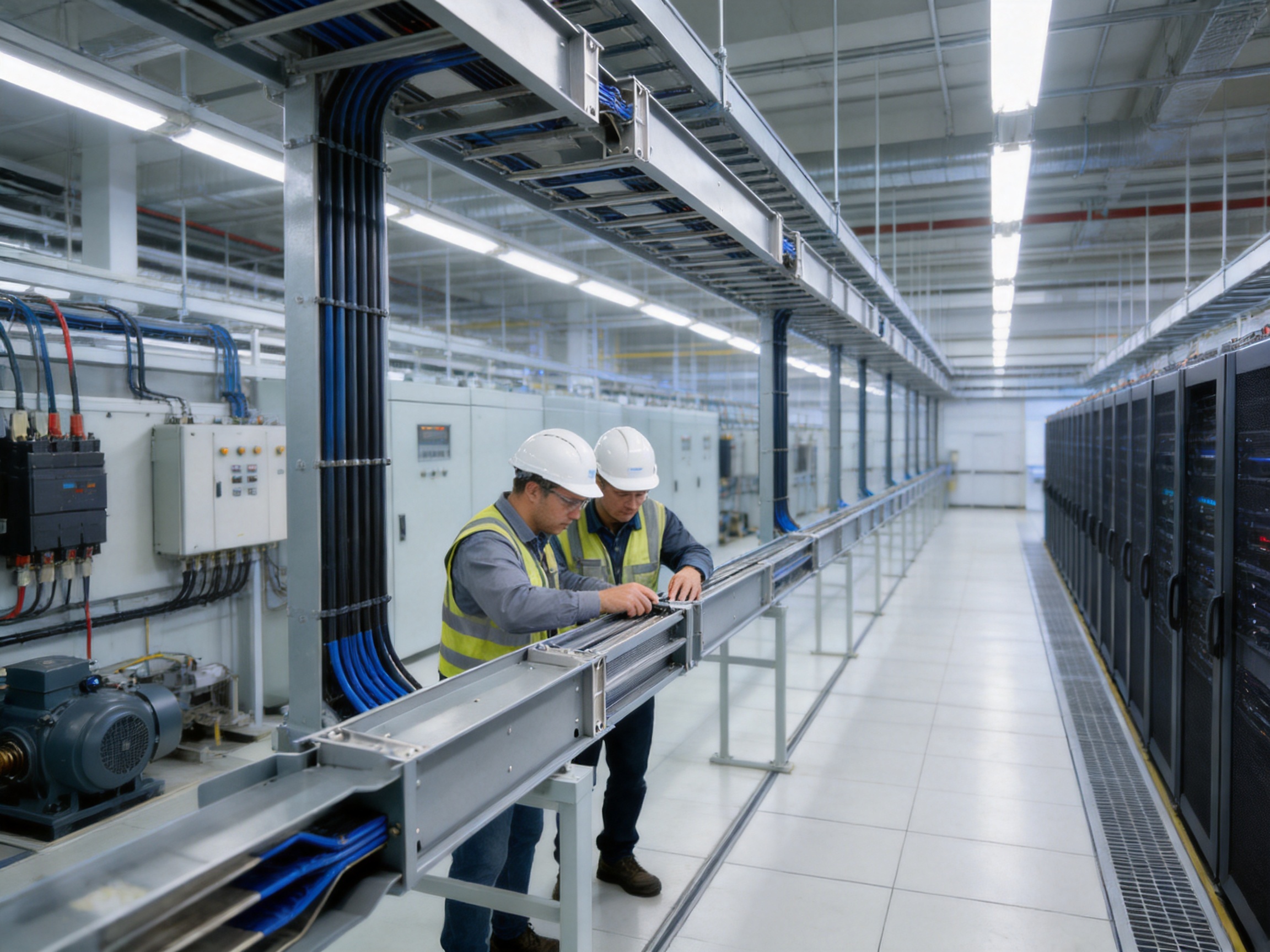
Data centers require reliable, scalable, and highly organized electrical distribution. Server loads can increase rapidly as computing capacity expands, and power must be supplied with minimal voltage fluctuation and minimal interruption.
A high-density busway for data-center applications can serve high-current routes, including systems approaching or exceeding 5000 A when the complete design is appropriately engineered. Plug-in tap-off units can supply server racks or row-based power distribution equipment while maintaining a clean and accessible installation layout.
The compact structure helps preserve valuable technical-floor and ceiling space. Low impedance can support voltage stability, while the sealed insulation system helps protect the distribution path from dust and accidental contact. Modular expansion allows additional rack capacity to be connected without replacing the entire main route.
Data-center designers should evaluate redundancy, selective coordination, maintenance bypass arrangements, monitoring, harmonic currents, neutral sizing, grounding, short-circuit ratings, and operating temperature. Busway is one part of the power architecture and must be integrated with switchboards, transformers, generators, uninterruptible power supplies, and rack-level protection.
5.2 Commercial Buildings
Office towers, shopping centers, hotels, hospitals, and mixed-use developments often require vertical rising mains and horizontal distribution routes. A busway can simplify the distribution of power between electrical rooms and floor-level panels.
The slim profile is useful in vertical shafts where space is limited. The modular route can also support tenant metering, floor-level distribution, mechanical equipment, lighting systems, and future fit-out changes.
Compared with multiple cable risers, a compact busway can provide a more organized installation with defined joint locations and easier visual inspection. The aluminum enclosure and enclosed conductors can also improve the appearance of visible electrical routes in commercial or architectural spaces.
5.3 Industrial Facilities
Manufacturing plants frequently require high-current distribution along production lines. Loads may include motors, welding equipment, automated machinery, conveyors, heating systems, and process equipment. Their locations may change as production requirements evolve.
A busway installed along a production line can provide multiple connection points for machinery. When equipment is relocated, the electrical distribution can often be adapted more easily than a fixed cable system. This supports shorter production-changeover periods and reduces the need for extensive cable tray modifications.
Industrial environments may contain dust, vibration, oil mist, humidity, and mechanical hazards. The enclosure rating, resin system, joint protection, support design, and material selection should therefore be matched to the specific environment. Additional protective measures may be needed in areas exposed to corrosive chemicals, extreme heat, or outdoor weather.
5.4 Transportation and Rail-Related Facilities
Rail stations, depots, maintenance workshops, airport facilities, and transportation terminals require organized power distribution across large and frequently occupied sites. Compact busway can be used for building services, equipment rooms, workshops, escalators, ventilation systems, and auxiliary power networks.
Its modular form can simplify installation in areas where access is limited or where construction must be coordinated with strict project schedules. The stated seismic capability up to intensity level 8 may also support applications requiring enhanced mechanical stability, subject to structural calculations and project-specific qualification.
5.5 Renewable-Energy and Wind-Power Facilities
Renewable-energy projects rely on specialized electrical systems that operate under demanding conditions. Wind-power facilities may use tubular and compact busbar systems in generators, towers, substations, and power collection arrangements.
The manufacturer’s wider product portfolio includes tubular busbars for wind-power applications, allowing related products to be considered within a coordinated supply strategy. For each renewable-energy installation, designers should consider vibration, temperature variation, humidity, altitude, electromagnetic behavior, maintenance access, and integration with converters and transformers.
5.6 Utility and Industrial Distribution Rooms
Substations, distribution centers, utility buildings, and large industrial plants often require high-capacity connections between transformers, switchgear, and downstream distribution boards. A compact busway can provide a defined route with high current capacity and reduced installation complexity.
The product is also suitable for projects where low-voltage distribution is connected to higher-voltage equipment through transformers. Its use does not replace the need for appropriate transformer protection, switchgear coordination, grounding, arc-flash assessment, or installation clearances.
6. Manufacturing Process and Quality Control
Advanced manufacturing is essential for a cast-resin busway because the electrical performance of the finished product depends on dimensional accuracy, resin quality, conductor preparation, curing control, joint assembly, and inspection discipline.
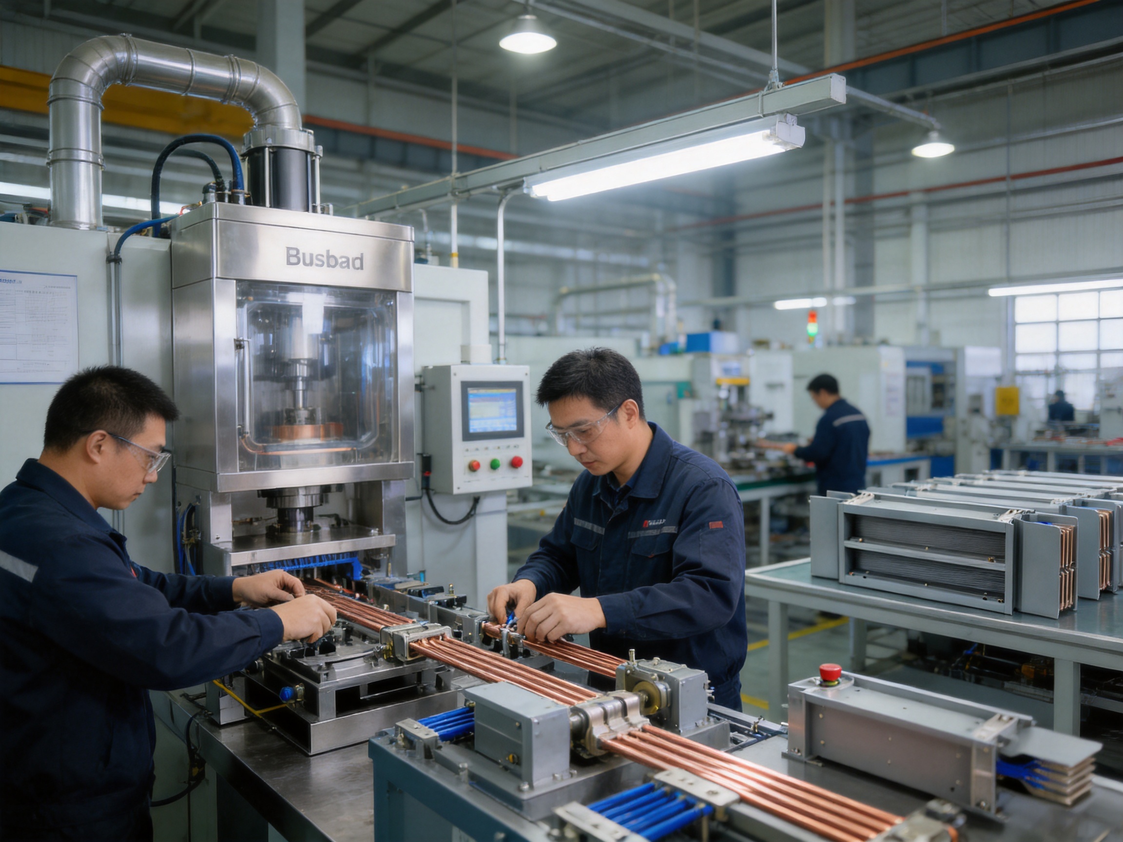
Jiangsu Wopeng Power Technology Co., Ltd. was founded in 2018 as a specialized high-tech enterprise focused on high- and low-voltage busbar systems. The company operates production lines equipped with vacuum casting systems, CNC machining equipment, and automated assembly technologies.
6.1 Engineering and Product Design
Manufacturing begins with engineering. The rated current, voltage, route configuration, conductor arrangement, insulation requirements, enclosure dimensions, joint structure, support method, and tap-off locations must be defined before production begins.
Engineering teams analyze the project’s electrical parameters and physical constraints. This may include route drawings, equipment interfaces, installation orientation, floor-to-floor dimensions, expansion requirements, environmental conditions, and access for transportation and maintenance.
Three-dimensional modeling and dimensional coordination can help identify clashes before manufacturing. This is especially valuable in complex facilities where busway routes pass through crowded service corridors or connect equipment from different suppliers.
6.2 Conductor Preparation
Copper bars are cut, formed, drilled, and prepared according to the design drawings. CNC machining equipment supports accurate hole positions, joint dimensions, and component interfaces. Dimensional control is important because even small variations can affect assembly alignment and connection quality.
Where tin plating is specified, the conductor surfaces are treated to achieve the required finish and contact properties. The prepared surfaces must be protected from contamination before assembly. Inspection may include dimensional checks, surface examination, and verification of material or plating requirements.
6.3 Resin Mixing and Vacuum Casting
Epoxy resin casting requires controlled preparation of resin components, fillers, pigments, and additives. The material must be mixed in the correct proportions and under suitable temperature and humidity conditions. Improper mixing or contamination can affect curing, mechanical strength, dielectric performance, and long-term reliability.
Vacuum casting equipment removes trapped air during resin introduction and helps fill the designed insulation spaces. Process parameters such as vacuum level, resin temperature, casting speed, mold condition, and curing temperature must be controlled carefully.
After casting, the product is cured according to the specified process. The curing cycle affects the final mechanical and electrical properties of the epoxy system. Production records can provide traceability for resin batches, casting conditions, curing cycles, and inspection results.
6.4 Enclosure Fabrication
Aluminum alloy profiles are cut and processed to form the enclosure sections. CNC equipment can provide consistent dimensions for holes, mounting interfaces, covers, and joint components. The enclosure is then assembled around the cast-resin conductor unit with the required phase barriers, covers, grounding provisions, and connection accessories.
Surface treatment may be applied according to environmental requirements. The selected finish should be compatible with the intended indoor, semi-outdoor, industrial, or corrosive environment. Enclosure continuity and grounding provisions must be verified during assembly.
6.5 Automated and Controlled Assembly
Automated assembly technologies help improve consistency in repetitive production operations. Controlled assembly reduces variation in fastener installation, component positioning, joint preparation, and accessory fitting.
Automation does not eliminate the need for skilled technicians. Experienced production personnel are required to interpret engineering drawings, inspect components, identify defects, manage special configurations, and verify that the finished assembly matches the approved design.
6.6 Inspection and Testing
Every busway system should undergo inspection and testing appropriate to its design and applicable standards. The manufacturer’s quality process includes high-voltage tests, insulation tests, mechanical verification, and routine quality checks.
High-voltage withstand testing evaluates the insulation system’s ability to tolerate a specified electrical stress. Insulation resistance testing provides information about the condition of the insulation and the absence of unintended conductive paths.
Mechanical verification may include checks of enclosure dimensions, joint alignment, mounting features, cover fit, connector operation, and structural integrity. Visual inspection confirms that cast surfaces, conductor interfaces, phase barriers, seals, and labels meet the required condition.
Testing collaboration with third-party institutions can provide independent validation of safety and performance. This is valuable for customers requiring documented technical evidence, project approval, or compliance with specific procurement standards.
7. The Manufacturer’s Engineering and Supply Strengths
Jiangsu Wopeng Power Technology Co., Ltd. focuses on the development and manufacture of high- and low-voltage busbar products. Its portfolio includes 35 kV epoxy resin vacuum-cast tubular busbars, low-voltage cast-resin busways, copper and aluminum tubular busbars, wind-power tubular busbars, compact busbar systems, and sliding contact line systems.
This product range gives the company experience across different conductor geometries, insulation technologies, voltage levels, and installation environments. Customers can therefore discuss related high-voltage, low-voltage, tubular, compact, and mobile power-supply requirements with one specialized busbar supplier.
7.1 Customized OEM Solutions
Electrical distribution routes are rarely identical from one project to another. Differences may include current rating, voltage, phase arrangement, neutral configuration, grounding method, enclosure size, route geometry, tap-off spacing, joint type, protection rating, and environmental requirements.
The company provides customized OEM solutions based on project specifications. Customization may include conductor material, dimensions, current capacity, connection positions, enclosure configuration, accessories, labeling, packaging, and documentation.
A customized approach is particularly useful for equipment manufacturers, system integrators, contractors, and engineering companies that need busway products compatible with their own distribution equipment or project standards.
7.2 Specialized Engineering Team
The company has engineers, technical specialists, and production professionals with experience in power equipment technology. Their responsibilities may include product design, electrical calculation, mechanical coordination, material selection, production planning, testing, and after-sales technical support.
Engineering support is important when a busway must be integrated with transformers, switchgear, generators, uninterruptible power supplies, motor-control centers, or industrial machinery. Proper interface coordination can reduce installation problems and improve commissioning efficiency.
7.3 Modern Production Equipment
Vacuum casting systems support the production of solid, reliable epoxy-resin insulation structures. CNC machining equipment improves dimensional accuracy in conductor and enclosure components. Automated assembly technologies help standardize repetitive processes and support higher production consistency.
Modern equipment is most effective when combined with process documentation, calibration, operator training, preventive maintenance, and quality traceability. The company’s manufacturing approach combines these elements to support repeatable production for both standard and customized busway configurations.
7.4 Quality Management and Field Experience
A quality management system establishes procedures for incoming material inspection, process control, product testing, nonconformance management, documentation, and final release. These controls are important for products used in high-current and critical operating conditions.
Wopeng products operate across more than 17 provinces and multiple industrial sectors. This field experience exposes the company to different climatic conditions, installation practices, application requirements, and customer expectations. Feedback from these applications can help improve product design and manufacturing procedures.
7.5 Complete Technical Support
A capable supplier should provide more than a physical busway section. Technical support may include product selection, route design, load assessment, accessory selection, interface drawings, installation guidance, testing documentation, and troubleshooting assistance.
For larger projects, coordination between the busway manufacturer, electrical designer, contractor, equipment supplier, and commissioning team is essential. Early communication reduces the risk of mismatched dimensions, incompatible connection interfaces, inadequate supports, or missing accessories.
8. Installation and Project Planning
Successful busway installation begins before the product arrives at the construction site. The route should be verified against architectural, structural, mechanical, fire-protection, and electrical drawings. Equipment locations, floor elevations, wall penetrations, support points, and maintenance clearances should be coordinated in advance.
8.1 Route Survey
A route survey confirms the actual site dimensions and identifies obstacles. The survey should record straight-run lengths, offsets, elevation changes, shaft dimensions, equipment connection positions, expansion joints, access restrictions, and lifting requirements.
As-built conditions may differ from early construction drawings. A final measurement before production can prevent costly modifications, delays, or field improvisation. For complex projects, digital survey data and coordinated three-dimensional models can improve accuracy.
8.2 Support and Alignment
Busway supports must be designed for the product weight, route orientation, seismic requirements, short-circuit forces, vibration, and building structure. Horizontal and vertical installations may require different support spacing and bracket arrangements.
Correct alignment is important at joints and equipment connections. Excessive mechanical stress should not be transferred to switchgear, transformers, or other connected equipment. Expansion and building movement should be considered where the route crosses structural separation joints or long uninterrupted distances.
8.3 Joint Assembly
Busway joints should be assembled by trained personnel using the specified hardware, torque values, insulation components, and sealing materials. Contact surfaces must be clean and free from damage. Incorrect torque can produce either excessive stress or insufficient contact pressure.
Joint covers and seals must be installed correctly to maintain the required protection rating. Any field modification should be approved by the manufacturer or responsible engineering authority. Unapproved drilling, cutting, or replacement of insulation components can compromise electrical and mechanical performance.
8.4 Commissioning
Before energization, the completed installation should be inspected for mechanical damage, missing covers, loose fasteners, incorrect phase identification, grounding continuity, and proper connection to upstream and downstream equipment.
Electrical testing may include insulation resistance, continuity, phase identification, protective-conductor verification, and other tests required by the project specifications. Test results should be recorded and reviewed by the responsible electrical engineer or commissioning authority.
9. Maintenance and Service Life
One of the advantages of a sealed cast-resin busway is reduced routine maintenance compared with systems containing many exposed cable terminations or open contact points. The product information indicates a service life of up to 30 years under appropriate operating and maintenance conditions.
Reduced maintenance does not mean that the system can be ignored. Periodic inspections should verify enclosure condition, joint covers, tap-off units, support structures, grounding continuity, signs of overheating, water ingress, contamination, and mechanical damage.
Thermal imaging can help identify abnormal temperature at joints or connection points while the system is energized, provided that the inspection is performed by qualified personnel under safe working procedures. Any unusual temperature rise, odor, discoloration, noise, or protective-device operation should be investigated promptly.
Tap-off units should be checked for secure engagement, correct protective-device operation, enclosure integrity, and signs of wear. Spare components should be stored in suitable conditions and identified by the correct product and rating information.
Maintenance records should include inspection dates, test results, modifications, protective-device settings, fault events, and replacement parts. This documentation supports safe operation and helps future maintenance teams understand the history of the installation.
10. Selecting the Correct Compact Busway
Product selection should begin with the electrical load rather than with physical dimensions alone. The designer should determine the continuous current, demand factor, load diversity, voltage, frequency, phase arrangement, neutral requirements, fault level, voltage-drop limit, and future expansion allowance.
10.1 Electrical Selection Factors
Rated current must be selected with adequate allowance for continuous loading, ambient temperature, harmonic currents, motor starting, future loads, and possible changes in the operating profile. High-current systems may require thermal calculations to confirm that the selected rating is suitable for the installation environment.
The short-circuit withstand rating must be greater than or equal to the prospective fault current for the required clearing time. Coordination between the busway and protective devices is essential. The upstream and downstream protection settings should be reviewed to ensure that faults are cleared without unnecessary disruption to healthy circuits.
Voltage drop should be calculated using the actual route length, conductor arrangement, operating current, power factor, and joint configuration. Low impedance is beneficial, but the final system performance depends on all connected components.
10.2 Environmental Selection Factors
Ambient temperature, humidity, altitude, dust, water, chemicals, vibration, seismic activity, and ultraviolet exposure may affect product selection. An IP65 configuration may be appropriate for many indoor or demanding environments, but more specialized protection may be needed for severe conditions.
In areas with corrosive gases or salt-laden air, the enclosure finish, fasteners, seals, and conductor plating should be reviewed. In high-altitude locations, reduced air density may affect insulation coordination and heat dissipation. In areas with significant vibration, support spacing and joint retention must be carefully assessed.
10.3 Mechanical and Architectural Factors
Available space, access routes, lifting equipment, ceiling height, shaft dimensions, maintenance clearances, and equipment interface positions should be considered at the design stage. Compact busway saves space, but it still requires sufficient room for installation, joint assembly, inspection, and replacement of accessories.
Vertical busway routes must be coordinated with floor penetrations, fire stopping, seismic supports, and building movement. Horizontal routes must be coordinated with ducts, pipes, cable trays, lighting, sprinkler systems, and structural beams.
11. Cost and Lifecycle Analysis
The initial purchase price of a compact busway may be higher than the price of some basic cable materials. However, a meaningful comparison should include the complete installed and operating cost rather than only the conductor cost.
Busway can reduce the quantity of support steel, cable trays, cable cleats, termination kits, fireproofing materials, and field labor. Its modular installation may shorten the construction schedule and reduce the cost of temporary works. Its smaller footprint may also reduce the cost of electrical rooms, shafts, and service corridors.
Over the operating life, lower losses may contribute to energy savings. The enclosed structure and reduced number of exposed connections may lower inspection and maintenance requirements. The ability to add tap-off units can reduce the cost of future modifications and help avoid major rewiring.
A lifecycle comparison should include purchase, transportation, installation, testing, commissioning, energy losses, maintenance, outage risk, expansion, and eventual replacement. For high-current facilities operating continuously, the energy and reliability benefits can be especially significant.
| Lifecycle Factor | Traditional Cable-Based Distribution | High-Density Compact Busway |
|---|---|---|
| Space requirement | May require wide trays, bending space, and multiple parallel routes | Compact integrated route with high power density |
| Installation method | Multiple cable pulling, dressing, termination, and testing operations | Prefabricated sections assembled with coordinated joints |
| Future expansion | May require additional cables and route modifications | Tap-off units can support modular expansion |
| Environmental protection | Depends on cable insulation, tray arrangement, and local protection | Cast-resin insulation and enclosure provide integrated protection |
| Maintenance | Many cable terminations and support points may require inspection | Sealed system with accessible joints and plug-in units |
| Voltage-drop control | Depends on parallel cable arrangement and termination consistency | Defined conductor arrangement and low-impedance route |
| Modification cost | Potentially high when equipment locations change | Generally easier where modular tap-off points are available |
12. Frequently Asked Questions
Q1: What is a high-density compact busway?
A high-density compact busway is a prefabricated low-voltage electrical distribution system with closely arranged copper conductors enclosed in a protective aluminum alloy housing. In this product, the conductors are insulated through epoxy resin vacuum casting, with flame-retardant phase barriers and modular plug-in connection units.
Q2: What current range can the product support?
The stated rated-current range is 400 A to 5000 A. Some compact busway technologies can be engineered for higher ratings, but the correct value depends on the manufacturer’s design, conductor configuration, thermal conditions, installation method, and applicable test certification.
Q3: Is compact busway suitable for data centers?
Yes. Its high current capacity, compact profile, low impedance, modular tap-off points, and expansion capability make it suitable for data centers. The complete power architecture must still address redundancy, selective coordination, harmonic currents, grounding, monitoring, and maintenance procedures.
Q4: Can compact busway replace all cable systems?
No distribution method is appropriate for every application. Compact busway is particularly advantageous for high-current, fixed-route, modular, and space-constrained installations. Cables may remain preferable for short flexible connections, irregular routes, moving equipment, temporary systems, or applications where busway installation is impractical.
Q5: How does epoxy resin casting improve performance?
Epoxy resin casting creates a solid insulation structure around the conductors. Vacuum processing helps reduce internal voids and supports consistent dielectric performance. The cast resin also protects the conductors against moisture, dust, accidental contact, and mechanical damage.
Q6: What does IP65 protection mean for the busway?
IP65 indicates a high level of protection against dust and water jets when the complete assembly is correctly manufactured, assembled, and sealed. The actual protection level can be reduced by damaged covers, incorrectly installed joints, unsealed cable entries, or unauthorized modifications.
Q7: How often should the busway be maintained?
Maintenance intervals should be determined by the installation environment, operating conditions, project requirements, and manufacturer recommendations. Periodic visual inspections, joint checks, grounding verification, and thermal examination are commonly considered. Critical facilities may require more frequent inspection and documented condition monitoring.
Q8: Can the busway be modified after installation?
Its modular design allows tap-off units to be added, removed, or repositioned where the system has been engineered for such changes. Modifications must be performed by qualified personnel and checked for current capacity, protective coordination, short-circuit withstand, enclosure integrity, and safe isolation.
Q9: What are the main advantages over traditional cable distribution?
The main advantages include reduced space requirements, faster installation, organized routing, low impedance, improved protection against dust and moisture, easier expansion, fewer field terminations, and potentially lower lifecycle costs. The actual benefit depends on project size, route length, load profile, and installation conditions.
Q10: What manufacturing technologies are used?
The manufacturing process includes epoxy resin vacuum casting, CNC machining, controlled conductor preparation, aluminum enclosure fabrication, automated assembly, high-voltage testing, insulation testing, mechanical verification, and routine quality inspection.
Q11: Can the manufacturer provide customized products?
Yes. Customized OEM solutions can be developed according to current rating, voltage, conductor material, route configuration, connection positions, protection rating, enclosure requirements, accessories, and project documentation needs.
Q12: What information should be provided when requesting a quotation?
Useful information includes rated voltage, rated current, frequency, phase and neutral configuration, short-circuit level, route drawings, straight-run lengths, bends, vertical sections, tap-off locations, equipment interfaces, protection rating, environmental conditions, installation orientation, delivery requirements, and applicable standards.
13. Why Choose a Specialized Busbar Manufacturer?
Busway is a critical power distribution component, so supplier selection should be based on more than price. A specialized manufacturer understands conductor design, insulation systems, current capacity, mechanical support, joint technology, casting processes, and electrical testing.
A specialist can identify potential problems before production, including inadequate clearances, unsuitable connection positions, insufficient short-circuit capacity, poor access for maintenance, and conflicts with other building services. This engineering involvement can reduce project risk and improve the reliability of the finished installation.
Jiangsu Wopeng Power Technology Co., Ltd. focuses specifically on busbar and related power transmission products. Its portfolio extends from low-voltage cast-resin busways to 35 kV tubular busbars, copper and aluminum tube busbars, wind-power products, compact systems, and sliding contact line systems.
The company’s manufacturing capabilities include vacuum casting systems, CNC equipment, automated assembly, and standardized inspection. Its technical team supports product development, customized design, production coordination, testing, and application assistance.
For customers seeking a custom insulated busbar manufacturer or tubular busbar system factory, this combination of product specialization, engineering experience, manufacturing capacity, and quality control provides a foundation for reliable project cooperation.
14. Conclusion
High-density compact busway is a practical response to the demands of modern electrical infrastructure. It combines high current capacity with compact dimensions, solid epoxy resin insulation, aluminum alloy housing, flame-retardant phase barriers, and modular plug-in connections.
Its advantages over many traditional distribution methods include efficient space utilization, faster installation, improved protection, controlled impedance, easier expansion, and reduced maintenance requirements. These characteristics make it suitable for data centers, commercial buildings, industrial plants, transportation facilities, renewable-energy projects, substations, and other high-current applications.
The product’s performance depends on more than its catalog rating. Correct engineering, route coordination, conductor selection, joint assembly, thermal assessment, grounding, protective coordination, commissioning, and maintenance are all essential. A reliable supplier should provide technical support throughout these stages.
With experience in high- and low-voltage busbar systems, Jiangsu Wopeng Power Technology Co., Ltd. provides customized solutions supported by epoxy resin vacuum casting, CNC machining, automated assembly, standardized testing, and a specialized engineering team. Its manufacturing and product capabilities allow customers to develop busway systems suited to specific current ratings, space restrictions, operating environments, and future expansion requirements.
When carefully designed and correctly installed, a high-density compact busway can provide a safe, durable, and efficient power distribution backbone for facilities that require dependable electrical performance in a compact and adaptable format.
References
1. IEC 61439, Low-Voltage Switchgear and Controlgear Assemblies, applicable parts and project editions.
2. IEC 60529, Degrees of Protection Provided by Enclosures, commonly known as IP Code.
3. UL 94, Tests for Flammability of Plastic Materials for Parts in Devices and Appliances.
4. Electrical installation design principles for low-voltage distribution systems, including current-carrying capacity, voltage drop, short-circuit withstand, grounding, and protective coordination.
5. Manufacturer technical information for low-voltage cast-resin busways, compact busway systems, tubular busbars, and related power distribution equipment.
6. Project specifications and engineering practices for data centers, industrial facilities, commercial buildings, substations, transportation infrastructure, and renewable-energy installations.
Product: High-density Compact Busway



-
 +86-180 3625 3000
-
 admin@wpbusbar.com
-
 No. 8, Yanjin Road, Chengxi Industrial Park, Shanyang Town, Baoying County, Yangzhou City, Jiangsu Province, China
Copyright © Jiangsu Wopeng Power Technology Co., Ltd.
All Rights Reserved.
 Custom Insulated Bus Bar Manufacturer
Tubular Busbar System Factory
Custom Insulated Bus Bar Manufacturer
Tubular Busbar System Factory