

 EN
EN

 English
 русский
 Français
 Español
 عربى
عربى


High-Density Compact Busway: A Reliable, Space-Efficient Solution for Low-Voltage Power Distribution
Content
- 1 1. What Is High-Density Compact Busway?
- 2 2. Core Product Positioning in Low-Voltage Distribution
- 3 3. Main Technical Specifications
- 4 4. Compact Structural Design and Space Efficiency
- 5 5. Epoxy Resin Casting and Full Insulation Protection
- 6 6. Electrical Performance and Heat Dissipation
- 7 7. Plug-In Modularity and Future Expansion
- 8 8. Applications in Data Centers
- 9 9. Applications in Industrial Manufacturing
- 10 10. Applications in Commercial and High-Rise Buildings
- 11 11. Applications in Renewable Energy and Infrastructure
- 12 12. Competitive Advantages Compared with Traditional Cable Systems
- 13 13. Manufacturing Process and Quality Control
- 14 14. Company Engineering and Supply Strengths
- 15 15. OEM and Customization Capabilities
- 16 16. Fire Safety and Mechanical Reliability
- 17 17. Installation Recommendations
- 18 18. Maintenance Strategy
- 19 19. Energy and Lifecycle Efficiency
- 20 20. How to Select the Correct Busway
- 21 21. Project Integration and Technical Support
- 22 22. Frequently Asked Questions
- 22.1 Q1: What is the primary purpose of a high-density compact busway?
- 22.2 Q2: What voltage and current ranges are available?
- 22.3 Q3: Is the busway fully insulated?
- 22.4 Q4: Why is epoxy resin casting advantageous?
- 22.5 Q5: Can the system be used in a data center?
- 22.6 Q6: Can a compact busway handle the same current as a conventional bus duct or cable system?
- 22.7 Q7: Is it easy to modify after installation?
- 22.8 Q8: Does a compact busway require maintenance?
- 22.9 Q9: Is the product suitable for outdoor use?
- 22.10 Q10: What information is needed for a quotation?
- 22.11 Q11: What makes a manufacturer technically reliable?
- 22.12 Q12: How long can the busway operate?
- 23 23. Conclusion
- 24 References
- 25 Product: High-density Compact Busway
Modern buildings, industrial facilities, data centers, renewable-energy installations, transportation systems, and commercial complexes all require electrical distribution equipment that can carry high currents safely while using as little space as possible. Traditional cable systems and older air-insulated bus ducts can perform reliably, but they often demand extensive support structures, large installation corridors, complex termination work, and significant maintenance effort. High-density compact busway provides an alternative approach by combining tightly arranged conductors, advanced insulation, modular construction, and high mechanical protection in a streamlined power distribution system.
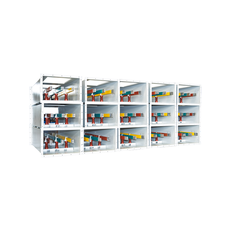
High-density compact busway belongs to the low-voltage cast-resin busway product category. It is designed for 0.4 kV low-voltage power distribution systems and uses epoxy resin casting technology to create a fully insulated electrical assembly. Copper conductors are arranged in a dense, multilayer structure, while a high-strength aluminum alloy enclosure provides mechanical protection and contributes to heat dissipation. The resulting system offers efficient current transmission, reduced space requirements, improved environmental resistance, and simplified installation compared with many conventional cabling arrangements.
Jiangsu Wopeng Power Technology Co., Ltd. develops and manufactures high- and low-voltage busbar systems for demanding electrical applications. Its product portfolio includes low-voltage cast-resin busways, 35 kV epoxy resin vacuum-cast tubular busbars, copper and aluminum tubular busbars, wind-power tubular busbars, compact busbar systems, and sliding contact line systems. Through engineering development, vacuum casting, CNC machining, automated assembly, standardized testing, and project-oriented technical support, the company provides busbar solutions for power generation, substations, wind energy, manufacturing, rail transit, and large commercial facilities.
This article examines the construction, technical characteristics, application value, manufacturing strengths, and competitive advantages of high-density compact busway. It also explains the factors that project engineers should consider when selecting a system for a new installation or an electrical upgrade.
1. What Is High-Density Compact Busway?
A high-density compact busway is a prefabricated electrical distribution system in which conductors are positioned closely together inside a protected enclosure. Instead of routing numerous individual cables through trays, conduits, or shafts, the busway provides a coordinated path for distributing electrical power from a transformer, switchboard, generator, or other source to downstream equipment.
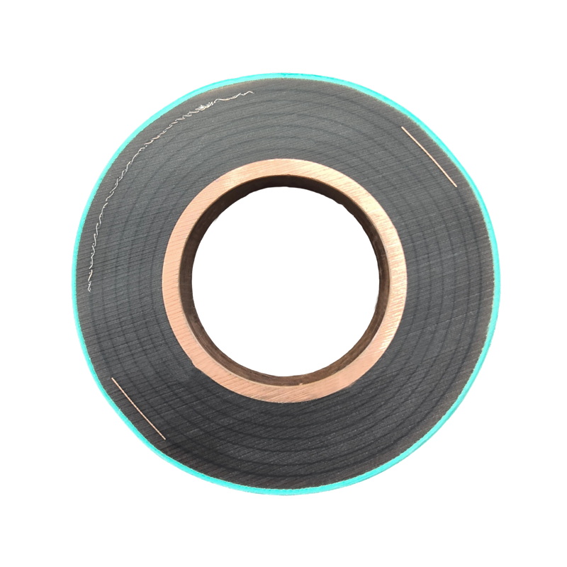
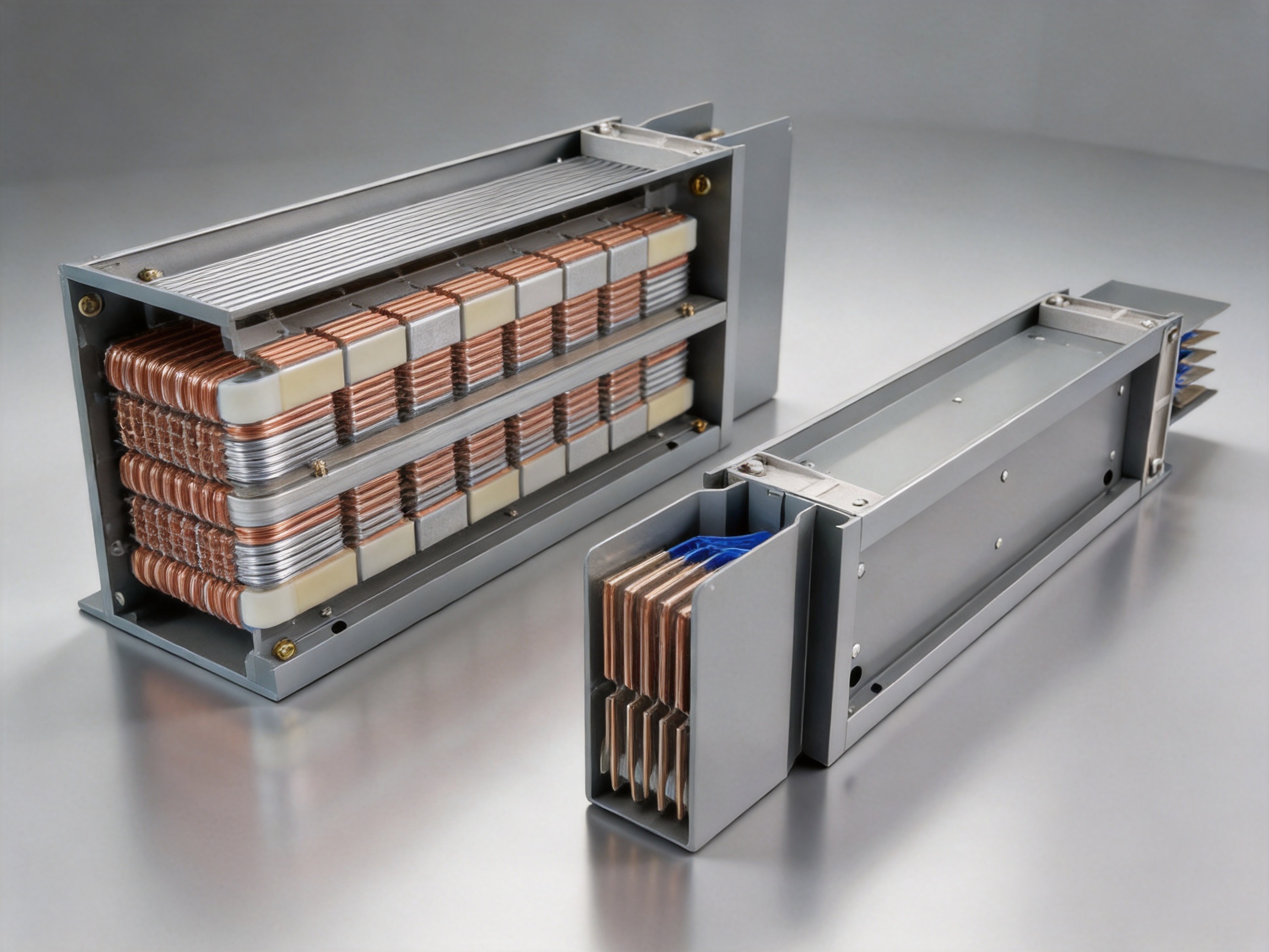
The conductors are commonly manufactured from high-purity copper busbars with a tin-plated surface. Copper provides high electrical conductivity and stable current-carrying performance, while tin plating helps improve surface reliability and resistance to oxidation. The conductors are arranged in multiple layers and separated by internal phase barriers. Epoxy resin is then introduced through an integrated casting process to form a dense, electrically insulated and mechanically stable assembly.
The use of epoxy resin casting distinguishes this product from conventional air-insulated bus duct systems. In an air-insulated arrangement, the conductors rely on physical spacing and air gaps for electrical separation. In a cast-resin system, the conductors are embedded within a solid insulation structure. This reduces exposure to dust, humidity, corrosive contaminants, accidental contact, and mechanical movement.
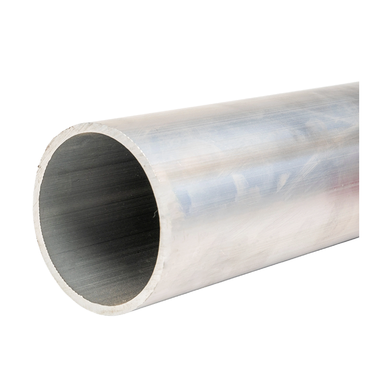
The enclosure is made from high-strength aluminum alloy profiles. Aluminum offers a useful balance between structural strength, corrosion resistance, low weight, and thermal performance. It also helps create a robust external surface that protects the cast-resin body during transportation, installation, and long-term operation.
The term “high-density” refers to the efficient arrangement of conductors and insulation within a compact cross-section. The design allows a high current rating to be delivered through a relatively slim system. Depending on the selected configuration, the rated current range can extend from 400 A to 5000 A. Some application discussions describe compact busway systems with ratings reaching 6300 A, but final capacity must always be confirmed against the actual product configuration, ambient conditions, installation method, thermal design, and applicable standards.
2. Core Product Positioning in Low-Voltage Distribution
In a low-voltage distribution network, the busway serves as an important connection and distribution device between the power source and end-use equipment. It may connect transformers to main switchboards, switchboards to distribution panels, or main distribution sections to production lines, mechanical equipment, server racks, and other loads.
For a 0.4 kV distribution system, the busway must provide more than simple current conduction. It must withstand thermal stress, short-circuit forces, vibration, installation movement, environmental exposure, and repeated connection operations. It must also maintain a stable insulation system throughout its service life.
High-density compact busway addresses these requirements through several coordinated design principles:
First, the conductors are arranged in a compact geometry to improve space utilization and control electrical impedance.
Second, epoxy resin casting creates a continuous insulation system that reduces the possibility of internal contamination, moisture penetration, and conductor movement.
Third, internal flame-retardant phase barriers help maintain safe separation between phases.
Fourth, the aluminum alloy enclosure provides mechanical protection and forms a defined external profile suitable for structured installation.
Fifth, plug-in connectors and modular sections allow the system to be configured for different building layouts and future expansion requirements.
These design features make compact busway suitable for projects where high current, limited space, reliable operation, and installation speed must be considered together.
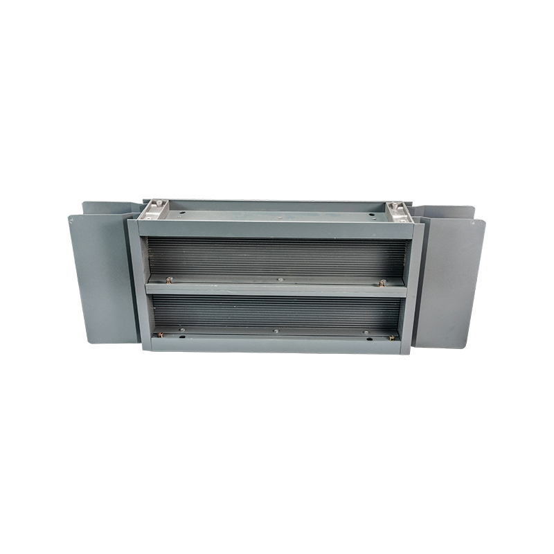
High-density Compact Busway
3. Main Technical Specifications
The standard technical characteristics associated with the high-density compact busway described in the supplied product information include the following:
| Technical Item | Typical Product Information | Project Significance |
|---|---|---|
| Product category | Low-voltage cast-resin busway | Provides a compact, fully insulated power distribution route |
| Application voltage | AC 400 V / 690 V | Suitable for common low-voltage distribution architectures |
| Rated current range | 400 A to 5000 A | Supports branch, feeder, and high-capacity main distribution applications |
| Insulation class | Class F | Provides enhanced thermal endurance for demanding operating conditions |
| Protection rating | Up to IP65 | Improves resistance to dust and water ingress when correctly configured |
| Conductor material | High-purity copper with tin plating | Supports conductivity, connection stability, and surface protection |
| Short-time withstand current | 50 kA for 1 second | Helps withstand short-circuit thermal and electrodynamic stress |
| Power-frequency withstand voltage | 3500 V for 1 minute | Supports insulation verification and electrical safety |
| Temperature-rise limit | Below 70 K | Helps control operating temperature under rated conditions |
| Fire performance | UL94 V-0 referenced for flame resistance | Reduces flame propagation risk in suitable configurations |
| Seismic capability | Up to seismic intensity level 8, subject to system verification | Supports use in areas requiring enhanced mechanical stability |
The values in the table provide a product reference framework rather than a substitute for a project-specific technical data sheet. A busway selection should be confirmed according to system voltage, rated current, frequency, short-circuit level, ambient temperature, installation direction, enclosure requirements, tap-off configuration, altitude, seismic conditions, and local electrical regulations.
The rated current range from 400 A to 5000 A allows the product family to cover many applications, from medium-capacity building feeders to high-current industrial and data-center distribution. The AC 400 V / 690 V rating also allows the system to serve common low-voltage architectures used in commercial buildings, factories, infrastructure facilities, and utility-related installations.
Class F insulation is useful where the equipment may experience elevated operating temperatures. However, insulation class alone does not determine the permitted operating temperature of the entire installation. The conductor configuration, resin formulation, enclosure design, joint construction, ventilation, ambient temperature, and installation conditions must all be considered in thermal calculations.
An IP65 protection rating, when achieved by the complete system and correctly maintained at joints and connection points, offers protection against dust and water jets. This is valuable in industrial environments, plant rooms, workshops, utility areas, and other locations where airborne particles or occasional water exposure may be present.
4. Compact Structural Design and Space Efficiency
The most visible advantage of a high-density compact busway is its efficient use of space. Electrical rooms and vertical shafts are often among the most constrained areas in a building. Conventional cable routes may require large trays, multiple support tiers, bending clearances, spare capacity, and additional fire-stopping arrangements. As the power demand increases, the required number and size of cables can increase rapidly.
A compact busway consolidates the conductors into a defined, factory-engineered enclosure. Its regular geometry makes it easier to coordinate with structural elements, ceiling systems, raised floors, equipment rooms, and vertical risers. In suitable projects, the space requirement may be reduced substantially compared with large cable groups or traditional bus duct arrangements.
The compact shape also reduces the visual and physical complexity of the distribution route. Instead of many parallel cable bundles, the installation can use a continuous busway line with standardized supports and connection points. This can simplify coordination with ventilation ducts, fire-protection systems, water pipes, communication routes, and other building services.
Space efficiency is especially important in data centers, high-rise buildings, hospitals, airports, industrial plants, and commercial renovations. In these environments, electrical capacity is increasing while available construction space remains limited. A smaller distribution system can help designers preserve valuable floor area and reduce the size of electrical shafts.
The dense conductor arrangement may also improve mechanical stability. When conductors are supported closely within a cast-resin body, the assembly is less susceptible to movement caused by vibration or short-circuit forces than loosely arranged conductors. The final performance depends on the design of the resin body, joints, supports, and enclosure, but the integrated structure provides a strong basis for mechanical reliability.
4.1 Benefits for Vertical Distribution
Vertical risers are a common application for compact busway. A vertical busway can be installed through a dedicated shaft or service zone, with tap-off units provided at selected floors. This arrangement can reduce the number of individual feeder cables running vertically through a building.
For high-rise residential, commercial, and mixed-use buildings, the modular design supports staged connection to floor distribution panels. For data centers and industrial facilities, the system can be aligned with equipment rows, production areas, or future expansion zones.
4.2 Benefits for Renovation Projects
Renovation projects frequently have limited ceiling height, congested service spaces, and incomplete information about existing cable routes. A compact busway can simplify the replacement or extension of an existing distribution route because its sections are prefabricated and its installation path is easier to define.
Although every retrofit requires a detailed survey, the modular nature of the busway can reduce the need for extensive cable pulling, large temporary work areas, and repeated on-site termination. This can be particularly useful when the facility must remain partially operational during construction.
5. Epoxy Resin Casting and Full Insulation Protection
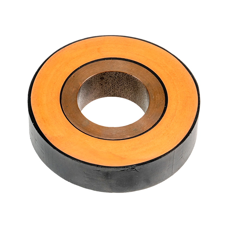
Epoxy resin casting is one of the most important technical features of the product. The resin surrounds the conductors and internal insulating elements, creating a solid insulation system with fewer voids and fewer exposed interfaces than an air-insulated design.
Vacuum casting technology is used to help remove air and reduce the risk of internal voids during the casting process. A void-free or low-void insulation structure is important because air pockets can create local electrical stress concentrations. Over time, such conditions may contribute to partial discharge, insulation aging, or reduced dielectric strength.
The cast-resin structure also limits the movement of contaminants inside the busway. Dust, moisture, and conductive particles have fewer paths through which they can reach the energized conductors. This is a significant advantage in manufacturing plants, workshops, transportation facilities, and other environments where airborne contamination may be higher than in a clean commercial building.
Full insulation protection can improve personnel safety by reducing the likelihood of accidental contact with energized conductive parts. It also supports stable phase-to-phase separation through the use of internal flame-retardant barriers. Nevertheless, safe operation still requires proper grounding, protective devices, access control, installation inspection, and compliance with applicable electrical codes.
Epoxy resin also contributes to mechanical reinforcement. Once cured, the resin helps hold the conductors in their designed positions and supports the assembly against vibration, impact, and short-circuit forces. This integrated construction can reduce the number of internal air spaces and loose components found in some traditional designs.
5.1 Resistance to Environmental Conditions
A fully insulated cast-resin busway is well suited to environments where humidity, dust, or occasional splashing may affect conventional equipment. The enclosure and joint system must be installed correctly to achieve the intended protection level. Particular attention should be given to end covers, expansion joints, tap-off openings, sealing components, and transitions between indoor and outdoor areas.
In corrosive environments, project engineers should assess the atmosphere, chemical exposure, cleaning agents, salt content, and enclosure finish before selecting the final configuration. Aluminum alloy provides useful corrosion resistance, but additional surface treatment or special materials may be required for severe environments.
6. Electrical Performance and Heat Dissipation
Electrical efficiency depends on conductor resistance, joint resistance, impedance, temperature, arrangement, and load profile. High-purity copper conductors provide low resistance and strong conductivity. Tin plating supports reliable contact surfaces at joints and connection points, helping reduce the risk of oxidation-related deterioration.
The compact busway is designed to maintain low impedance and minimize electrical losses. Lower impedance helps reduce voltage drop along the distribution route, which is especially important for sensitive electronic equipment, long feeder runs, high-current motors, and data-center loads.
Heat dissipation must be carefully managed because the conductors carry substantial current within a compact enclosure. The product information identifies a temperature-rise limit below 70 K under specified test conditions. This indicates that the system is designed to control conductor and enclosure temperature within an acceptable range when operated according to its rated parameters.
The aluminum alloy enclosure can contribute to thermal performance by providing a conductive external surface that transfers heat to the surrounding environment. The detailed thermal behavior depends on enclosure geometry, conductor spacing, resin characteristics, ambient temperature, installation orientation, ventilation, and the presence of adjacent busway sections.
Compared with large cable groups, a busway can offer more predictable thermal coordination because the conductor arrangement is engineered and tested as a system. Cable installations may be affected by grouping factors, tray arrangement, spacing, insulation type, ambient conditions, and uneven current distribution. A busway does not eliminate these engineering considerations, but it can make the overall system easier to model and standardize.
6.1 Temperature Rise and Load Planning
When specifying the product, the design current should not simply equal the maximum expected load. Engineers should consider demand factors, continuous-load requirements, future expansion, harmonic currents, ambient temperature, ventilation, and the possibility of overload operation.
Data centers may experience high and relatively continuous loads. Industrial plants may have motors, variable-frequency drives, welders, furnaces, and other equipment with distinctive current profiles. Commercial buildings may have significant diversity between lighting, HVAC, elevators, pumps, and tenant loads. Each application should therefore be reviewed individually.
6.2 Short-Circuit Withstand Capability
The stated short-time withstand current of 50 kA for 1 second indicates that the system is designed to withstand significant short-circuit stress for the specified duration. During a fault, conductors experience both thermal energy and electrodynamic forces. Compact positioning and cast-resin support can help maintain conductor geometry during this event.
The final short-circuit rating must be coordinated with upstream protective devices, transformer impedance, system fault level, connection length, and protection-clearing time. A project must not rely on the busway rating alone. Protection coordination and fault-current analysis are essential to verify that the complete distribution system remains within its design limits.
7. Plug-In Modularity and Future Expansion
One of the most practical advantages of a compact busway system is its modular design. Plug-in units can be positioned along the route to supply local equipment without requiring a separate cable run from the main switchboard for every load.
Depending on the design, plug-in points may be provided at regular intervals such as 500 mm to 1000 mm. These intervals allow tap-off boxes or branch connection units to be placed near equipment locations. The exact spacing, rating, and permissible accessories must be confirmed for each product series.
Modularity is valuable in dynamic facilities. Data centers add server racks and power distribution units over time. Manufacturing plants modify production lines. Commercial buildings change tenant layouts. Warehouses install new automation systems. A busway with strategically planned tap-off points can accommodate these changes more easily than a fixed cable network.
Expansion can also be more orderly. Instead of adding new cable trays and pulling new feeders through congested routes, a facility may be able to install additional tap-off units or extend the busway with compatible sections. This reduces the amount of disruptive construction work required for future modifications.
Any modification must still follow formal electrical safety procedures. The system must be correctly isolated or designed for approved live-plug-in operation, depending on the product and local regulations. Tap-off units must match the busway rating, phase arrangement, protection requirements, and mechanical interface. Unauthorized field modifications should not be permitted.
7.1 Installation Efficiency
Prefabricated busway sections can reduce installation time because the conductors, insulation, enclosure, and connection interfaces are manufactured as a coordinated product. Field installation typically focuses on setting supports, positioning sections, joining units, installing covers, connecting tap-off boxes, and completing electrical inspection.
Compared with routing and terminating large numbers of individual cables, this approach can reduce labor requirements and shorten the construction schedule. The supplied product information indicates that modular installation can improve installation efficiency by more than 60% in suitable applications, while other project comparisons commonly estimate a 30% to 50% installation-time advantage over complex cable installation. Actual savings depend on route length, site access, labor skills, lifting requirements, joint design, testing, and the complexity of the building.
Fast installation is not merely a cost benefit. Shorter installation periods can reduce interference with other trades, lower the time that equipment rooms remain unavailable, and help contractors meet demanding project schedules. Factory-produced sections can also improve dimensional consistency compared with fully site-assembled cable systems.
7.2 Maintenance and Accessibility
A sealed, fully insulated system can reduce maintenance exposure compared with installations that have numerous exposed cable terminations or accessible conductive surfaces. The reduced number of individual cables and terminations may simplify inspection and cleaning.
However, maintenance-free operation should not be interpreted as zero inspection. Operators should periodically check supports, joints, enclosure continuity, grounding, tap-off units, thermal conditions, and signs of mechanical damage. Infrared inspection, insulation testing, torque verification, and protective-device testing may be appropriate depending on the facility and operating environment.
8. Applications in Data Centers
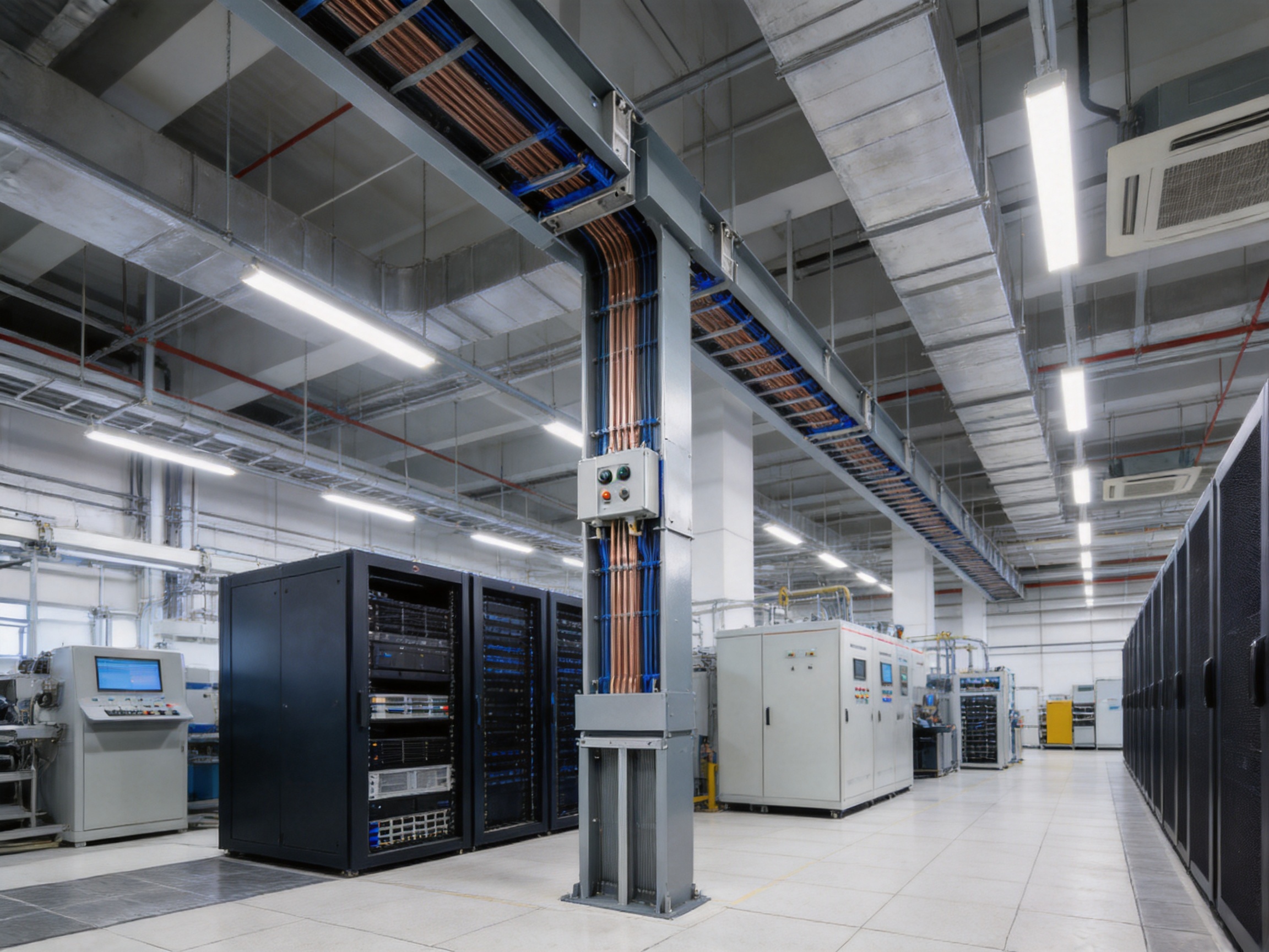
Data centers require electrical distribution systems that combine high capacity, low voltage drop, flexibility, and high availability. A high-density compact busway is suitable for these requirements because it can deliver high currents in a relatively small footprint while allowing connections to be added near server equipment.
Data-center electrical layouts change frequently. Server racks may be added, relocated, or replaced. Power density may increase as computing hardware becomes more powerful. A fixed cable system can make these changes labor-intensive because new feeders must be routed, terminated, tested, and coordinated with existing services.
A busway installed above server rows can provide a structured distribution path. Tap-off boxes can connect to rack-level power distribution units or other downstream equipment. This configuration can help maintain a clean, organized ceiling space and reduce the amount of cable congestion above racks.
Low impedance is also important in data centers. Excessive voltage drop can affect power quality and equipment stability. The copper-conductor design and compact geometry help support efficient power transfer, although the final voltage-drop result depends on busway length, current, power factor, frequency, connection resistance, and load balance.
Data centers also require careful redundancy planning. A compact busway can be integrated into A-side and B-side distribution architectures, provided that the system is correctly divided and coordinated with transformers, generators, uninterruptible power supplies, switchgear, and rack-level equipment. The busway itself does not create redundancy; redundancy results from the complete electrical topology and the separation of critical sources and paths.
9. Applications in Industrial Manufacturing
Industrial plants often require flexible power distribution for motors, machine tools, welding equipment, conveyors, cranes, furnaces, compressors, and automated production lines. These loads may be distributed over large areas and may change as production processes evolve.
Compact busway can provide a continuous feeder route along production areas, with tap-off boxes positioned near machines. This approach can reduce the length of individual cable runs and support cleaner separation between power distribution and other plant services.
The cast-resin structure is useful in environments with dust, vibration, and mechanical activity. The sealed design can reduce the exposure of energized conductors to industrial contaminants. In areas with oil mist, chemical vapors, high humidity, or abrasive particles, however, the complete system should be evaluated for compatibility with the specific environment.
In manufacturing facilities, downtime has a direct effect on productivity. A modular distribution system can make future equipment connections more predictable and may reduce the construction disruption associated with line modifications. Proper shutdown planning, lockout procedures, and protection coordination remain essential during any changeover.
10. Applications in Commercial and High-Rise Buildings
Commercial buildings typically contain a mixture of lighting, HVAC equipment, elevators, pumps, tenant spaces, retail areas, communication systems, and life-safety equipment. Electrical loads may be distributed across multiple floors and may change during the building’s service life.
Vertical busway risers can provide a compact alternative to multiple parallel cable groups. Floor-level tap-off units can supply distribution panels, tenant electrical rooms, or other local loads. The regular shape of the busway helps simplify coordination in service shafts and plant rooms.
High-rise projects benefit from the reduced weight and space requirement of a consolidated distribution route. A compact system may also reduce the amount of structural support and fireproofing associated with large cable bundles, although all penetrations and fire compartments must be treated according to local building regulations.
Commercial renovation projects can benefit from modular extension. When a tenant changes its electrical requirements, additional branch connections may be installed at planned locations. This flexibility can support building owners who want to preserve future leasing and fit-out options.
11. Applications in Renewable Energy and Infrastructure
Renewable-energy projects frequently involve high-current connections between power-conversion equipment, transformers, switchgear, and collection systems. Wind-power installations, photovoltaic facilities, energy-storage systems, and hybrid power plants may operate in environments with vibration, temperature variation, dust, moisture, and demanding maintenance conditions.
The broader product portfolio associated with Jiangsu Wopeng Power Technology includes tubular busbars for wind-power applications and other high- and low-voltage busbar systems. This experience across multiple busbar technologies can support project coordination when a renewable-energy facility requires different busbar types at different voltage levels.
For infrastructure projects such as rail transit facilities, utility buildings, industrial substations, and large public facilities, the compact busway can provide an organized route for high-current low-voltage distribution. The product’s insulation, enclosure, mechanical construction, and modularity are relevant where reliability and maintainability are important design priorities.
12. Competitive Advantages Compared with Traditional Cable Systems
High-density compact busway competes primarily with cable trays, conduit-and-cable assemblies, and certain forms of conventional bus duct. Each technology has appropriate applications, but compact busway offers several advantages where high current and limited space are significant concerns.
12.1 Reduced Space Requirement
A busway consolidates multiple conductors into a compact factory-designed enclosure. Traditional cable systems may require wider trays, larger bends, greater separation, and additional clearance for installation and maintenance. The compact profile can free space for mechanical systems, building services, storage, or future equipment.
12.2 More Predictable Installation
Cable installation depends heavily on site labor, pulling routes, bend radii, cable weight, termination quality, and field conditions. Busway sections are manufactured to defined dimensions and assembled through standardized connection procedures. This can improve installation predictability and reduce the risk of inconsistent field workmanship.
12.3 Lower Connection Complexity
Large cable feeders may require many parallel cables per phase, multiple lugs, extensive termination space, and careful phase identification. Compact busway reduces the number of individual conductors that must be terminated at each major connection point. Plug-in distribution can further simplify branch connections.
12.4 Improved Environmental Protection
Cast-resin insulation and an enclosed aluminum alloy housing protect the conductors from many common environmental influences. The system is less dependent on maintaining clean air gaps around individual conductors, although joint sealing and enclosure integrity remain essential.
12.5 Expansion Flexibility
A well-planned busway route can include future tap-off points or spare capacity. This makes it suitable for facilities that are expected to expand or change. Traditional cable systems can also be extended, but the extension may require new trays, larger supports, additional cable pulling, and more extensive shutdown work.
12.6 Potential Lifecycle Savings
The initial purchase price of a busway may be higher than the price of some cable materials. However, a complete cost comparison should include labor, supports, fire-stopping, installation duration, testing, maintenance, floor-space value, future modifications, and energy losses. In many high-current applications, the total lifecycle cost can favor compact busway.
| Comparison Factor | Traditional Cable Distribution | High-Density Compact Busway |
|---|---|---|
| Space requirement | Often greater because of trays, bends, grouping, and clearance | Compact and geometrically organized |
| Field labor | High cable pulling and termination workload | Prefabricated sections and standardized joints |
| Branch connections | Separate cable routes and terminations may be required | Tap-off units can be positioned along the route |
| Environmental exposure | Depends on cable insulation, tray location, and enclosure arrangements | Cast-resin insulation and enclosed construction provide additional protection |
| Future modification | May require new cables, trays, and shutdowns | Modular extension and plug-in flexibility |
| Thermal coordination | Strongly affected by cable grouping and installation arrangement | Factory-defined conductor and enclosure arrangement |
| Visual organization | Multiple cable bundles and support systems | Clean, continuous distribution route |
| Maintenance | Many individual cables and terminations may require inspection | Fewer major conductors and integrated joints, with scheduled inspection still required |
13. Manufacturing Process and Quality Control
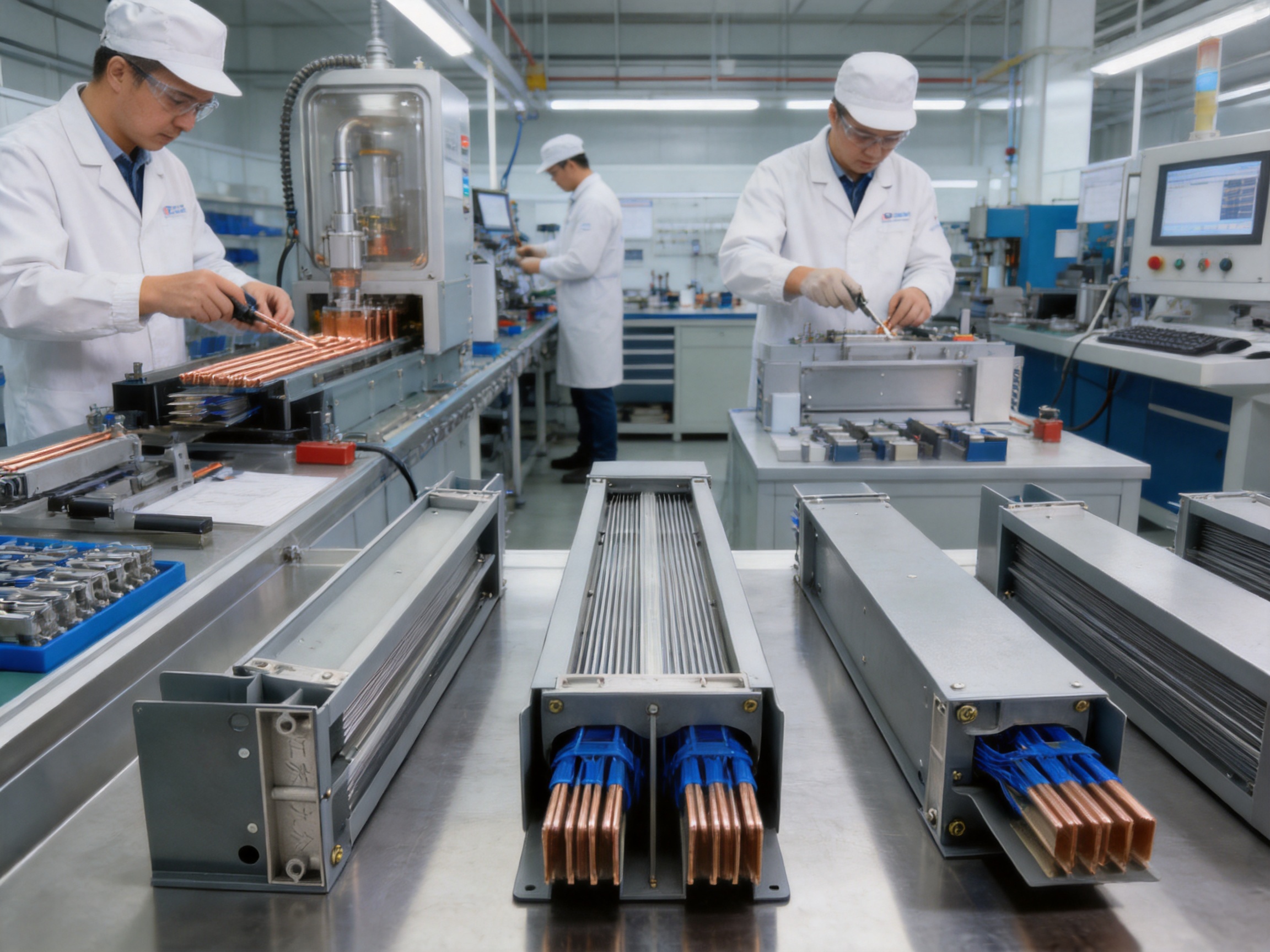
The performance of a cast-resin busway depends greatly on manufacturing control. Electrical conductors, insulating resin, enclosure components, joints, and accessories must work together as one engineered system. Jiangsu Wopeng Power Technology supports its product development and manufacturing activities with vacuum casting systems, CNC machining equipment, automated assembly technologies, and standardized inspection procedures.
13.1 Engineering and Product Design
Manufacturing begins with electrical and mechanical design. Engineers determine conductor dimensions, phase spacing, insulation thickness, enclosure geometry, joint construction, support locations, tap-off positions, and thermal characteristics.
Design work must account for rated current, voltage, power frequency, short-circuit forces, temperature rise, installation orientation, environmental conditions, and project-specific dimensions. Three-dimensional modeling and production drawings can help coordinate the busway with building structures and connected equipment.
For customized orders, the manufacturer may review the route length, direction changes, vertical sections, expansion requirements, flanges, end connections, transformer interfaces, switchboard connections, and branch tap-off locations. This project-based approach helps ensure that the delivered sections correspond to the actual installation conditions.
13.2 Conductor Preparation
High-purity copper conductors are cut and machined according to the specified dimensions. Connection areas may be drilled, shaped, or otherwise processed using CNC equipment to achieve consistent tolerances. Tin plating is applied to relevant conductor surfaces to improve contact performance and surface protection.
Dimensional control is important because conductor alignment affects insulation thickness, joint fit, current distribution, and connection reliability. CNC machining helps reduce variation between production batches and supports repeatable assembly.
13.3 Insulation and Resin Casting
Epoxy resin casting is a key manufacturing stage. The conductors and insulating components are arranged in the required multilayer structure, placed within the casting tooling, and prepared for resin injection. Vacuum processes help remove trapped air and improve the integrity of the finished insulation body.
The resin formulation, mixing ratio, temperature, curing profile, mold condition, and vacuum level must be controlled carefully. Inadequate process control can lead to voids, incomplete filling, dimensional instability, or variations in dielectric performance. A disciplined casting process helps produce a solid and consistent insulation system.
After curing, the cast body is inspected for surface defects, dimensional accuracy, and proper integration with the conductor assembly. Additional machining may be carried out where necessary to prepare connection points or interface surfaces.
13.4 Enclosure Manufacturing
High-strength aluminum alloy enclosure profiles are processed to the required lengths and configurations. CNC machining and controlled assembly help ensure that covers, joints, supports, and connection interfaces align correctly.
The enclosure must provide mechanical protection without interfering with insulation clearances or thermal performance. Grounding and equipotential bonding arrangements must also be properly integrated. Depending on the application, surface treatments may be used to improve appearance, durability, or resistance to environmental exposure.
13.5 Automated and Standardized Assembly
Automated assembly technologies can improve repeatability in the installation of phase barriers, covers, joint components, and accessories. Standardized work instructions help production personnel follow consistent procedures for torque, alignment, sealing, and inspection.
Factory assembly provides an important advantage over fully site-built electrical routes. The manufacturer can control the working environment, use dedicated tooling, verify dimensions before shipment, and conduct routine electrical tests before the product reaches the project site.
13.6 Inspection and Testing
According to the supplied company information, products undergo standardized inspection processes that include high-voltage tests, insulation tests, mechanical verification, and routine quality checks. Cooperation with third-party testing institutions provides an additional method of independent validation.
Typical inspection activities for a cast-resin busway may include conductor resistance measurement, insulation resistance testing, power-frequency withstand testing, dimensional inspection, enclosure continuity verification, joint inspection, and visual examination of the cast-resin body.
Where required by the project, type testing or third-party verification may address temperature rise, short-circuit withstand, dielectric performance, ingress protection, mechanical strength, fire behavior, and seismic response. The applicable test standards depend on the destination market, system design, and customer specification.
14. Company Engineering and Supply Strengths
Jiangsu Wopeng Power Technology Co., Ltd. was founded in 2018 as a specialized high-tech enterprise focused on the research, development, and manufacturing of high- and low-voltage busbar systems. Its product range covers voltage levels from low voltage to 35 kV, allowing the company to support different sections of a power distribution project.
The company’s portfolio includes epoxy resin vacuum-cast tubular busbars, low-voltage epoxy-cast busbar trunking, copper and aluminum tubular busbars, wind-power tubular busbars, compact busbar systems, and sliding contact line power supply systems. This breadth is valuable for customers who need several power-conduction technologies from one technical source.
Experience with both tubular busbars and compact busways provides a broader understanding of conductor geometry, insulation, thermal management, mechanical support, connection design, and project integration. It also allows the manufacturer to compare different product structures when recommending a solution for a particular voltage, current, environment, or installation route.
The company has built a team of engineers, technical specialists, and production professionals with experience in power equipment technology. Its manufacturing capabilities include vacuum casting equipment, CNC machining, automated assembly, and standardized inspection. These resources support both repeat production and customized OEM solutions.
For international customers, customization may involve conductor material, current rating, voltage level, enclosure dimensions, tap-off arrangement, connection interfaces, installation direction, labeling, documentation, and testing requirements. A capable manufacturer should be able to review these requirements before production and provide drawings or technical documents for approval.
The company reports that its products operate across more than 17 provinces and important industrial sectors in China. Applications include power generation, substations, wind energy, industrial manufacturing, rail transit, and large commercial facilities. This range of field applications indicates experience with different operating conditions and project requirements.
15. OEM and Customization Capabilities
Electrical distribution routes are rarely identical from one project to another. Even when two projects use the same current rating, they may require different lengths, bends, tap-off locations, connection flanges, enclosure arrangements, or installation supports.
A custom busway manufacturer should therefore offer more than a standard catalog. It should provide technical review, route planning, interface confirmation, production drawings, inspection documentation, packaging coordination, and after-sales support.
For a customized high-density compact busway, the customer may need to provide the following information:
System voltage and frequency.
Rated current and expected load profile.
Short-circuit current and protective-device clearing time.
Number of phases and neutral requirements.
Conductor material and plating requirements.
Route length, section dimensions, bends, offsets, and vertical transitions.
Connection details for transformers, switchboards, generators, or distribution panels.
Tap-off quantity, rating, position, and protection requirements.
Indoor or outdoor installation conditions.
Ambient temperature, humidity, dust, chemical exposure, and altitude.
Seismic, fire, ingress-protection, and mechanical requirements.
Applicable standards, inspection procedures, and documentation requirements.
When this information is reviewed at the design stage, the manufacturer can reduce the risk of field changes and interface problems. Proper customization also helps ensure that the busway’s thermal, mechanical, and electrical characteristics correspond to the actual project.
16. Fire Safety and Mechanical Reliability
Fire safety is a major consideration in power distribution equipment, particularly in high-rise buildings, data centers, transportation facilities, hospitals, and industrial plants. The supplied product information references UL94 V-0 fire performance for the insulation system. UL94 V-0 is associated with a material’s ability to self-extinguish under specified laboratory conditions.
Fire performance should always be evaluated as part of the complete busway assembly rather than by considering the resin material alone. The enclosure, joints, tap-off units, seals, supports, penetrations, and surrounding construction all affect the fire behavior of the installed system.
The cast-resin body provides a solid insulating structure and can reduce the presence of exposed combustible materials around energized conductors. Internal flame-retardant phase barriers help maintain separation between phases and support safer operation under abnormal conditions.
Mechanical reliability is equally important. The busway may be exposed to transportation vibration, installation impact, building movement, equipment vibration, or seismic activity. The product information indicates resistance up to seismic intensity level 8, subject to configuration and verification. To achieve the intended performance, supports, anchors, joints, and building interfaces must be designed for the local seismic conditions.
In areas with significant vibration, engineers should review the connection to transformers, switchgear, and rotating equipment. Flexible links or expansion arrangements may be required to prevent mechanical stress from being transferred into the busway body.
17. Installation Recommendations
Although compact busway is designed for efficient installation, quality workmanship remains essential. Before delivery, the project team should confirm the route, access conditions, lifting method, storage area, installation sequence, and connection interfaces.
Busway sections should be stored in a clean, dry, and protected location. Cast-resin surfaces, joint interfaces, tap-off openings, and sealing components should be protected from impact, contamination, and moisture before installation.
Supports must be positioned according to the manufacturer’s drawings. Excessive span lengths can create mechanical stress, while incorrect alignment can make joint assembly difficult. Vertical runs may require dedicated support arrangements to carry the weight of the sections and accessories.
At each joint, installers should verify conductor alignment, insulation surfaces, fastener condition, torque values, enclosure continuity, phase identification, and sealing. Joint covers must be installed correctly, and unused tap-off openings must remain protected according to the product design.
Connections to transformers, switchboards, and other equipment should account for movement, thermal expansion, alignment tolerances, and short-circuit forces. Rigidly forcing a busway into an incorrectly positioned connection can damage the joint or place stress on the enclosure.
After installation, the system should undergo appropriate inspections and tests. These may include visual inspection, insulation resistance testing, power-frequency withstand testing where required, phase-sequence verification, grounding continuity testing, torque checks, and functional testing of tap-off units and protective devices.
18. Maintenance Strategy
The integrated structure of a cast-resin busway can reduce routine maintenance compared with systems containing many exposed cable connections, but a preventive maintenance plan is still recommended. The inspection interval should be based on the operating environment, load level, criticality, manufacturer recommendations, and applicable regulations.
Maintenance personnel should inspect the external enclosure for corrosion, deformation, loose covers, impact damage, water entry, and signs of overheating. Joint areas should be checked for discoloration, unusual odor, surface cracking, or evidence of thermal stress.
Tap-off units should be examined for correct mechanical engagement, enclosure condition, protective-device operation, and cable termination integrity. If the busway is installed in a dusty or humid environment, additional attention should be given to seals, covers, and ventilation conditions.
Thermal imaging can help identify abnormal heating at joints, tap-off connections, or cable interfaces. Any hot spot should be investigated rather than ignored. Possible causes include loose fasteners, overload, unbalanced current, damaged contact surfaces, inadequate ventilation, or incorrect installation.
Where required, insulation resistance and dielectric tests should be carried out using procedures suitable for the cast-resin system. Testing must be performed by qualified personnel, with sensitive downstream equipment isolated as necessary to prevent damage.
19. Energy and Lifecycle Efficiency
The compact busway is designed to provide low impedance and low transmission losses. Reduced electrical losses can contribute to lower energy consumption, particularly in high-current systems operating continuously or for long periods.
The supplied product information indicates that the system can reduce overall energy consumption by 25% compared with conventional cabling in suitable applications. The actual result depends on conductor size, route length, load factor, joint resistance, ambient conditions, voltage level, power factor, harmonic content, and the performance of the alternative cable system. A project-specific loss calculation should be used when making a formal energy claim.
Lifecycle efficiency also includes installation labor, maintenance, expansion, downtime, and space utilization. A busway that costs more initially may provide a better total economic result if it significantly reduces installation time, avoids extensive building modifications, simplifies future changes, and maintains stable electrical performance.
The stated service life can reach up to 30 years when the system is correctly selected, installed, operated, and maintained. Service life is influenced by thermal cycling, environmental exposure, short-circuit events, mechanical damage, connection quality, and the condition of associated equipment.
20. How to Select the Correct Busway
The first selection factor is rated current. The busway should be sized for the continuous design current while allowing for demand, future expansion, ambient conditions, and possible load growth. Oversizing may increase initial cost, while undersizing can create unacceptable temperature rise and operational risk.
The second factor is system voltage and insulation coordination. The selected busway must match the nominal system voltage, maximum operating voltage, power-frequency withstand requirement, impulse conditions where applicable, and the insulation coordination of connected equipment.
The third factor is short-circuit performance. Engineers should determine the prospective fault current and verify the busway’s short-time and peak withstand capability. Protective-device coordination should ensure that fault duration remains within the busway’s tested limits.
The fourth factor is the environment. Indoor clean-room conditions differ significantly from industrial workshops, coastal facilities, underground spaces, and outdoor substations. Ingress protection, corrosion resistance, fire performance, temperature, humidity, altitude, and chemical exposure should be reviewed.
The fifth factor is route geometry. A complete route survey should identify straight sections, elbows, offsets, vertical sections, expansion joints, end connections, and transitions. Accurate dimensions reduce field modification and improve installation efficiency.
The sixth factor is the tap-off strategy. Designers should determine how many branch units are required, where they should be located, and whether future positions should be reserved. The rating and protection of each tap-off unit must match the connected load.
The seventh factor is compliance. The product should be evaluated against the standards and certification requirements of the target market. Documentation may include technical data sheets, test reports, drawings, installation manuals, quality certificates, and inspection records.
21. Project Integration and Technical Support
A successful busway project involves cooperation among the manufacturer, electrical consultant, contractor, equipment supplier, and facility operator. Early technical communication can prevent problems at transformer and switchboard interfaces, building penetrations, support locations, and tap-off positions.
The manufacturer should review the single-line diagram, load schedule, fault-level information, route drawings, equipment elevations, and installation conditions. Where necessary, the manufacturer can help confirm busway ratings, section lengths, joint quantities, flange arrangements, and accessory requirements.
Technical drawings should be approved before production. The approval process should verify dimensions, phase sequence, neutral and protective-earth arrangements, connection orientation, tap-off direction, enclosure finish, labeling, and shipping divisions.
For international OEM projects, communication should also cover packaging, export documents, spare parts, test certificates, language requirements, site supervision, and commissioning support. A supplier with experience in customized production can help coordinate these details more effectively than a supplier offering only a standard product.
22. Frequently Asked Questions
Q1: What is the primary purpose of a high-density compact busway?
Its primary purpose is to distribute low-voltage electrical power between a source and downstream equipment through a compact, enclosed, and modular conductor system. It is especially useful where high current, limited space, environmental protection, and future expansion are important.
Q2: What voltage and current ranges are available?
The product information identifies AC 400 V and 690 V applications with rated currents from 400 A to 5000 A. Some compact busway product families may extend to higher ratings, such as 6300 A. The final rating must be confirmed against the selected design and project requirements.
Q3: Is the busway fully insulated?
The product uses epoxy resin casting technology to create a fully insulated conductor assembly. Internal phase barriers and the cast-resin body help separate and protect the conductors. Correct joint assembly, enclosure installation, grounding, and inspection are still required for safe operation.
Q4: Why is epoxy resin casting advantageous?
Epoxy resin casting creates a solid insulation system that reduces exposure to dust, moisture, accidental contact, and mechanical movement. Vacuum casting can reduce internal voids and improve insulation consistency. The resin also helps reinforce the conductor assembly mechanically.
Q5: Can the system be used in a data center?
Yes. High-density compact busway is suitable for many data-center applications because it supports high current in a compact route and can accept modular tap-off units near server rows. Redundant electrical paths, power quality, cooling coordination, and maintenance bypass arrangements must be designed at the complete system level.
Q6: Can a compact busway handle the same current as a conventional bus duct or cable system?
Modern compact busway systems can be engineered for current ratings comparable to or higher than many traditional systems. The actual capacity depends on conductor size, thermal design, installation conditions, enclosure configuration, and testing. A direct comparison should use complete technical data rather than only the external dimensions.
Q7: Is it easy to modify after installation?
The modular design can make modification easier than adding new cable routes. Tap-off boxes may be added at suitable positions, and additional busway sections may be installed where the design permits. All changes must follow approved isolation, protection, mechanical, and testing procedures.
Q8: Does a compact busway require maintenance?
It requires less routine attention in some applications because the conductors are enclosed and the number of exposed connections is reduced. It should nevertheless be inspected periodically for joint condition, enclosure damage, overheating, grounding continuity, tap-off security, and environmental exposure.
Q9: Is the product suitable for outdoor use?
Some configurations may be suitable for outdoor or semi-outdoor use when the required enclosure, sealing, corrosion protection, temperature range, and installation accessories are provided. Outdoor suitability should be confirmed with the manufacturer for the specific project rather than assumed from the indoor product rating.
Q10: What information is needed for a quotation?
A quotation normally requires the voltage, current, route length, number of phases, conductor material, short-circuit level, installation environment, straight and bent-section dimensions, connection interfaces, tap-off requirements, protection rating, applicable standards, and delivery requirements.
Q11: What makes a manufacturer technically reliable?
Important indicators include engineering capability, controlled resin casting, accurate conductor machining, automated or standardized assembly, documented testing, traceable quality procedures, project experience, customization capability, and technical support before and after delivery.
Q12: How long can the busway operate?
The supplied information identifies a service life of up to 30 years under suitable conditions. Actual service life depends on correct sizing, installation, environmental control, maintenance, connection quality, and avoidance of abnormal thermal or mechanical events.
23. Conclusion
High-density compact busway provides a modern method for distributing electrical power in low-voltage systems. Its combination of compact conductor arrangement, epoxy resin casting, copper conductors, tin-plated connection surfaces, aluminum alloy enclosure, modular tap-off capability, and factory-controlled production offers clear advantages for high-current and space-constrained projects.
Compared with traditional cable systems, the product can reduce route congestion, simplify installation, improve environmental protection, support future expansion, and create a more organized electrical infrastructure. Compared with conventional air-insulated bus ducts, its solid insulation structure can provide stronger resistance to dust, moisture, accidental contact, and mechanical movement when properly designed and installed.
The product is suitable for applications including data centers, industrial manufacturing, high-rise buildings, commercial facilities, renewable-energy projects, transportation infrastructure, substations, and other critical low-voltage distribution environments. Its technical range includes AC 400 V / 690 V systems, current ratings from 400 A to 5000 A, Class F insulation, protection up to IP65, a short-time withstand current of 50 kA for 1 second, and a power-frequency withstand voltage of 3500 V for 1 minute, subject to the selected configuration and test conditions.
Jiangsu Wopeng Power Technology Co., Ltd. strengthens this product offering through experience in high- and low-voltage busbar systems, vacuum casting, CNC machining, automated assembly, quality inspection, OEM customization, and third-party testing cooperation. Its broader product portfolio and project experience allow it to support customers seeking reliable power transmission equipment across multiple voltage levels and industries.
For the best result, high-density compact busway should be selected as part of a complete electrical engineering process. Accurate load calculations, fault-current analysis, thermal verification, route coordination, interface design, installation supervision, and preventive maintenance are all essential. With these factors properly addressed, a compact cast-resin busway can provide an efficient, safe, durable, and adaptable foundation for modern power distribution.
References
1. Product technical information for high-density compact low-voltage cast-resin busway, including rated current, voltage, insulation class, protection rating, withstand current, withstand voltage, and temperature-rise data.
2. Manufacturer information concerning epoxy resin vacuum casting, CNC machining, automated assembly, routine inspection, and third-party testing cooperation.
3. General principles of low-voltage busbar trunking system design, installation, protection coordination, thermal performance, and maintenance.
4. IEC 61439 series, Low-Voltage Switchgear and Controlgear Assemblies, applicable sections for power switchgear and controlgear assemblies.
5. IEC 60529, Degrees of Protection Provided by Enclosures, commonly known as IP Code.
6. UL 94, Tests for Flammability of Plastic Materials for Parts in Devices and Appliances.
7. General engineering guidance for short-circuit withstand assessment, insulation coordination, temperature-rise verification, and electrical distribution system reliability.
8. Project-specific electrical codes, building regulations, fire-safety requirements, and installation standards applicable in the country of use.
Product: High-density Compact Busway




-
 +86-180 3625 3000
-
 admin@wpbusbar.com
-
 No. 8, Yanjin Road, Chengxi Industrial Park, Shanyang Town, Baoying County, Yangzhou City, Jiangsu Province, China
Copyright © Jiangsu Wopeng Power Technology Co., Ltd.
All Rights Reserved.
 Custom Insulated Bus Bar Manufacturer
Tubular Busbar System Factory
Custom Insulated Bus Bar Manufacturer
Tubular Busbar System Factory