

 EN

 English
 русский
 Français
 Español
 عربى
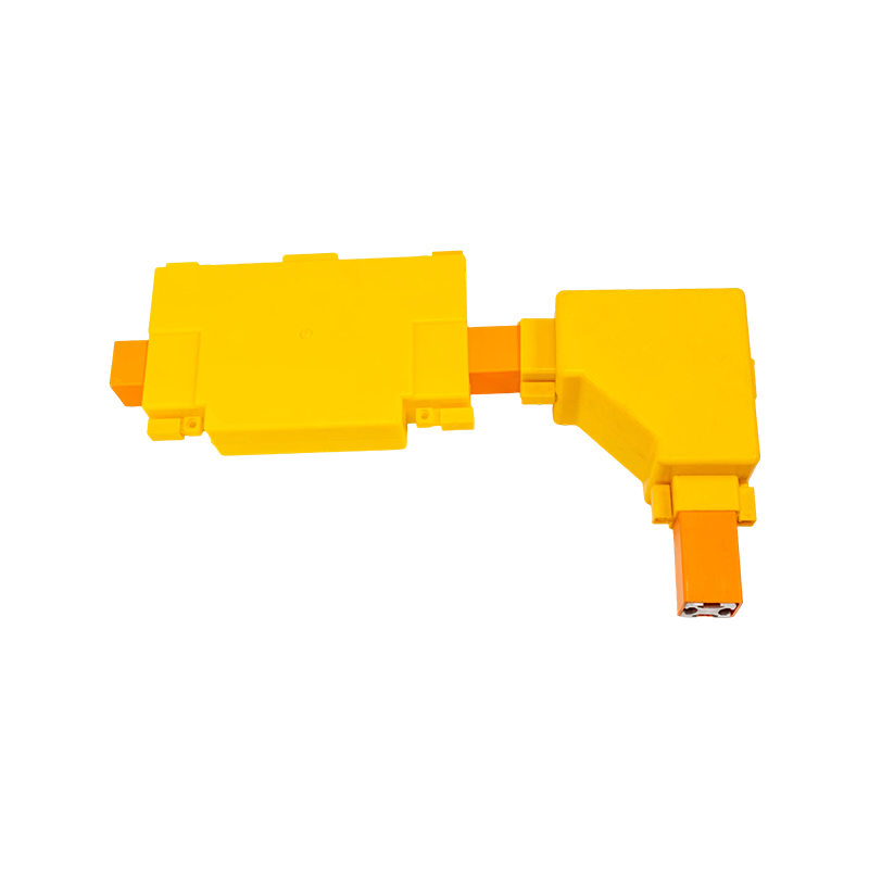

Epoxy Resin Casting Tubular Bus Bar: Advanced Insulated Power Transmission for Demanding Electrical Systems
Content
- 1 1. What Is an Epoxy Resin Casting Tubular Bus Bar?
- 2 2. Why Epoxy Resin Casting Is Important
- 3 3. Electrical and Mechanical Performance Advantages
- 4 4. Environmental Protection and Operational Reliability
- 5 5. Advantages Over Conventional and Competing Busbar Solutions
- 6 6. Advanced Manufacturing Process
- 7 7. Quality Control and Testing
- 8 8. Typical Applications
- 9 9. Installation and Commissioning Considerations
- 10 10. Maintenance and Service Life
- 11 11. Customization and Engineering Support
- 12 12. Company Manufacturing Strengths
- 13 13. Frequently Asked Questions
- 13.1 Q1: What is the main advantage of an epoxy resin casting tubular busbar?
- 13.2 Q2: Is the product suitable for medium-voltage systems?
- 13.3 Q3: What conductor materials are available?
- 13.4 Q4: What is the service life?
- 13.5 Q5: Can the tubular busbar be installed outdoors?
- 13.6 Q6: What is the maximum suspended span?
- 13.7 Q7: How are the joints connected to transformers and switchgear?
- 13.8 Q8: How is the busbar grounded?
- 13.9 Q9: Does the product require regular maintenance?
- 13.10 Q10: What information is needed for a quotation?
- 13.11 Q11: How does the product compare with cables?
- 13.12 Q12: Can the product be monitored?
- 14 14. Conclusion
- 15 References
- 16 Product: Epoxy Resin Casting Tubular Bus Bar
Reliable power transmission is essential in substations, industrial facilities, renewable energy projects, transportation infrastructure, commercial buildings, and other installations where electrical continuity and safety cannot be compromised. As power systems become more compact, higher in capacity, and more exposed to demanding environmental conditions, conventional open conductors and loosely protected connection systems may not provide sufficient protection against moisture, dust, mechanical impact, electrical tracking, or accidental contact. Epoxy Resin Casting Tubular Bus Bar technology addresses these challenges by combining a high-conductivity tubular conductor with a fully integrated, molded insulation and shielding structure.
An epoxy resin casting tubular bus bar is a factory-manufactured power transmission assembly in which the conductor, insulation, shielding layers, and protective outer structure are formed into a highly integrated unit. Unlike a conventional busbar arrangement assembled from separate insulation components, supports, barriers, and connection accessories, the cast tubular design is produced through a controlled vacuum injection and curing process. This creates a compact, mechanically stable, and electrically protected product suitable for medium- and high-current applications.
Jiangsu Wopeng Power Technology Co., Ltd. develops and manufactures insulated busbar systems, tubular busbars, cast resin busways, copper and aluminum alloy tubular busbars, wind power tubular busbars, compact busbar systems, and sliding contact line systems. Its product range covers applications from low-voltage distribution to medium-voltage power transmission, including 35 kV epoxy resin vacuum-cast tubular busbar systems. The company combines automated vacuum casting, precision machining, automated assembly, electrical testing, and engineering support to provide customized power transmission solutions.
1. What Is an Epoxy Resin Casting Tubular Bus Bar?
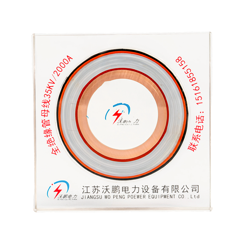
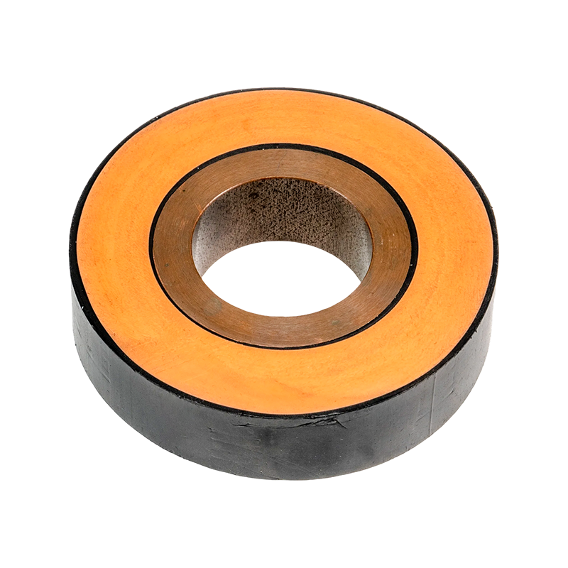
An Epoxy Resin Casting Tubular Bus Bar is an insulated electrical conductor manufactured by placing a copper or aluminum tubular conductor inside a carefully designed insulation and shielding system, followed by vacuum injection of specially formulated epoxy resin. Pressure injection and high-temperature curing produce a solid, continuous structure around the conductor. The result is a busbar that is not dependent on multiple detachable insulation pieces for its basic dielectric protection.
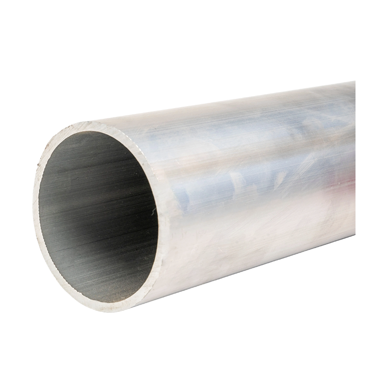
The tubular conductor provides an efficient current path and favorable mechanical characteristics. The cast epoxy insulation provides electrical isolation, environmental protection, and structural support. Additional semiconductive, metallic, and protective layers can be integrated into the overall construction to control the electric field, improve shielding, and provide a reliable grounding path. Depending on the voltage level and installation requirements, the insulation thickness and external configuration can be customized.
The product described in the supplied technical information uses TZ7 or higher-grade oxygen-free copper, with a copper content of at least 99.90 percent for the pure copper tube. High-purity copper helps maintain low electrical resistance and limits conductor losses. Alternative tubular busbar configurations may use aluminum alloy conductors where reduced weight, installation flexibility, or project-specific economic considerations are important.
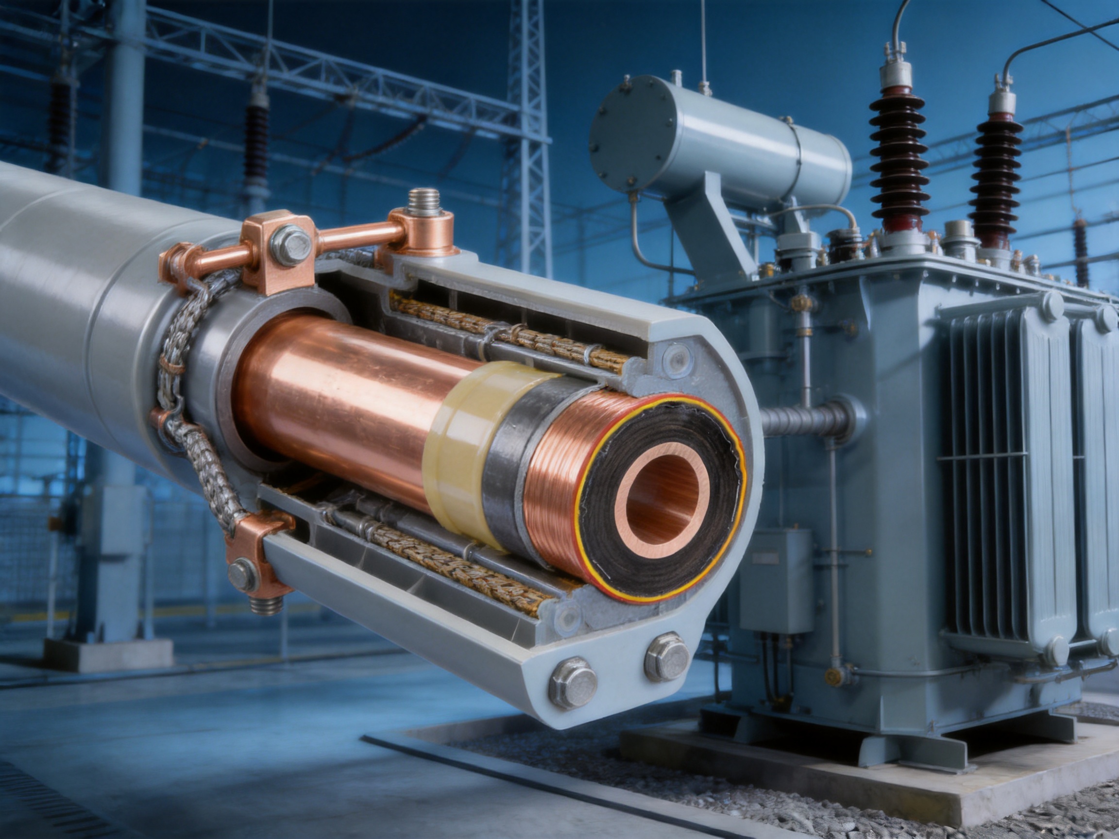
One of the defining characteristics of the epoxy resin casting process is that the conductor and insulation system are formed into an inseparable body. The integrated structure can include the conductor, inner shielding layer, semiconductive corrugated paper, outer shielding layer, metal shielding layer, and external protective layer. This arrangement reduces the number of interfaces that may otherwise become weak points under thermal cycling, vibration, humidity, or mechanical stress.
Core Components of the Product
The conductor is the primary current-carrying element. Copper is selected for projects requiring high conductivity, compact dimensions, and strong short-circuit performance. The conductor ends are prepared for low-resistance connections, and the end of the copper tube is rounded to reduce stress concentration and improve connection quality. The conductor connection surface may be plated with silver or tin to help reduce contact resistance and improve corrosion resistance.
The insulation system is based on cast epoxy resin. The resin is injected under vacuum and cured at elevated temperature, allowing the material to fill the designed mold and form a dense insulation body. Vacuum processing helps reduce voids and other defects that can adversely affect dielectric performance. The finished insulation must be carefully controlled for thickness, dimensional accuracy, surface quality, and adhesion to the surrounding layers.
Semiconductive and shielding layers support electric-field control. A metal shielding layer is used to provide electromagnetic shielding and a defined grounding reference. The supplied product information identifies a composite shielding arrangement using tinned steel strip and copper strip in one description, while another construction requirement refers to copper braided tape and copper strip. The final shielding design should therefore be confirmed against the approved technical drawing and project specification for each order.
The grounding system connects the metal shielding layer to the site grounding network. Copper stranded or braided grounding wires are reliably welded to the metal shielding layer, and grounding points are marked and numbered for installation and maintenance. Waterproofing and moistureproofing measures are applied at grounding points to prevent moisture penetration into the insulation system.
Terminal joints are molded together with the conductor through a one-shot forming process. Intermediate connections use an embedded stainless steel clamp welding structure. The stated design objective is for the temperature rise at terminal joints to remain lower than the temperature rise of the conductor body. Connections between the tubular busbar terminals and external equipment are made through flexible links secured with bolts, helping accommodate installation tolerances and reduce mechanical stress transferred to equipment terminals.
2. Why Epoxy Resin Casting Is Important
The casting method is more than a manufacturing convenience. It directly influences the electrical, mechanical, and environmental performance of the finished busbar. In a conventional installation, many separate components must be assembled in the field. Every interface creates a potential location for contamination, moisture accumulation, mechanical loosening, or uneven electrical stress. A factory-cast structure moves much of the critical insulation and shielding work into a controlled production environment.
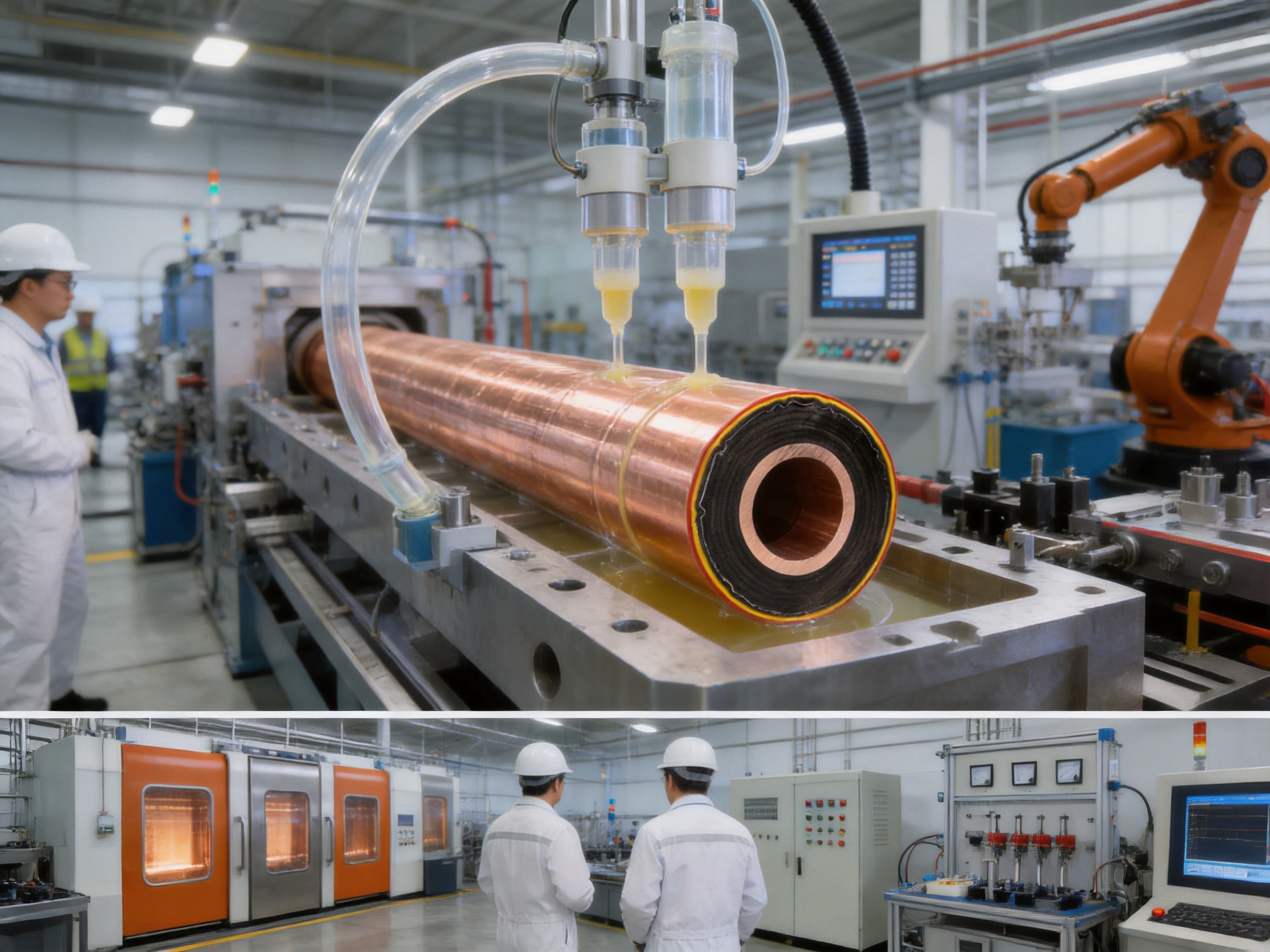
WOPENG uses a fully automatic dual-component vacuum injection molding process. Two liquid resin components are accurately metered and mixed before being injected into the mold. Pressure injection improves material flow, while vacuum processing helps remove air and minimize internal voids. High-temperature curing completes the chemical reaction and creates the required mechanical and dielectric properties.
The integrated process offers several important advantages:
Consistent resin distribution around the conductor and internal layers.
Reduced risk of air pockets and localized dielectric weakness.
Improved dimensional control through dedicated molds and tooling.
Better repeatability between production batches.
Strong mechanical bonding between insulation and associated layers.
Reduced dependence on field-applied insulation work.
More reliable protection against dust, moisture, and accidental contact.
Automated production is particularly valuable for busbars used in medium-voltage and high-current systems. Such products must maintain consistent insulation thickness, conductor alignment, terminal geometry, and shielding continuity. Small dimensional variations can affect installation, electrical clearances, field distribution, and connection performance. Automated molding and inspection help control these variables more effectively than manually assembled insulation systems.
The use of a nonseparable construction also supports long-term reliability. During operation, busbars may experience repeated heating and cooling, short-circuit forces, vibration, transportation stress, and changes in ambient humidity. A continuous molded body is less likely to shift or separate than a system made from many loosely fitted external parts. This does not eliminate the need for correct installation and inspection, but it can reduce the number of mechanical and electrical interfaces that require attention.
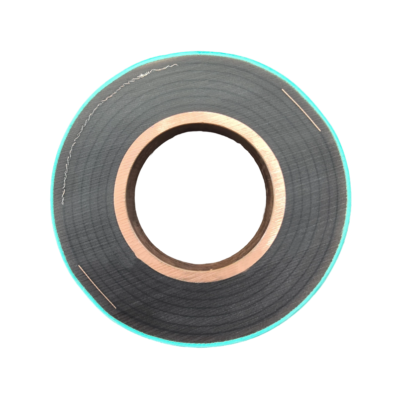
Epoxy Resin Casting Tubular Bus Bar
3. Electrical and Mechanical Performance Advantages
The principal advantage of an epoxy resin casting tubular busbar is the combination of current-carrying capability and insulation integrity. The tubular conductor can transmit substantial current while the surrounding insulation maintains a controlled separation from grounded structures, adjacent phases, building components, and personnel.
High Conductivity and Efficient Current Transmission
TZ7 or higher-grade copper with a copper content of at least 99.90 percent provides a low-resistance current path. High-purity copper also supports predictable electrical performance during design calculations. In high-current systems, reducing conductor resistance is important because resistive losses produce heat and reduce overall energy efficiency.
The tubular form can provide a favorable ratio between electrical capacity, mechanical stiffness, and material usage. It can also simplify the routing of high-current connections between transformers, switchgear, generator terminals, and distribution assemblies. Depending on the project design, the tubular conductor may be selected in different diameters and wall thicknesses to achieve the required current rating, short-circuit withstand, and mechanical strength.
High current ratings must always be determined from the complete approved design rather than from a general product description. Relevant factors include conductor size, conductor material, installation orientation, ambient temperature, enclosure conditions, permissible temperature rise, ventilation, short-circuit duration, altitude, and connection design. The supplied product information notes that standard models may carry up to 3500 A, while customized higher-current configurations may be available. The final rating should be confirmed through the manufacturer's technical calculation and test documentation.
Stable Insulation Performance
Epoxy resin is used because it can provide high dielectric strength, mechanical rigidity, and resistance to many environmental influences when properly formulated and processed. The supplied technical material describes an epoxy insulation layer with a breakdown voltage of at least 30 kV/mm and insulation resistance above 1.0 × 10¹³ ohms. These figures should be understood as product or material design references and verified against the applicable test reports for the specific model.
Insulation thickness is selected according to the voltage level and design requirements. The supplied reference values list approximately 10 mm for 10 kV, 15 mm for 35 kV, 20 mm for 66 kV, 30 mm for 110 kV, and 45 mm for 220 kV. Actual insulation thickness may vary according to the electrical design, standards, creepage requirements, partial-discharge performance, mechanical structure, and project conditions.
| Nominal Voltage Level | Reference Insulation Thickness | Typical Design Considerations |
|---|---|---|
| 10 kV | Approximately 10 mm | Medium-voltage distribution and equipment connections |
| 35 kV | Approximately 15 mm | Substations, industrial plants, and high-capacity distribution |
| 66 kV | Approximately 20 mm | Higher-voltage transmission within specialized installations |
| 110 kV | Approximately 30 mm | High-voltage connection systems subject to project-specific design |
| 220 kV | Approximately 45 mm | Specialized high-voltage applications requiring detailed engineering |
The values in this table are reference values from the supplied material and should not replace a formal insulation coordination study. Each project must verify clearances, creepage distance, partial-discharge requirements, impulse withstand, power-frequency withstand, and environmental correction factors.
Low Temperature Rise at Connections
Connections are often among the most thermally sensitive parts of a power transmission system. Poor contact pressure, inadequate surface preparation, contamination, insufficient overlap, or improper bolt tightening can increase contact resistance. The resulting heat may accelerate insulation aging and reduce operational reliability.
The tubular busbar design addresses connection performance through carefully formed terminal joints, embedded stainless steel clamp welding at intermediate connections, and plated conductor end surfaces. The stated product requirement is that the temperature rise at terminal joints be lower than the temperature rise of the conductor body. This reflects the importance of making the joint at least as thermally efficient as the conductor itself.
Flexible links between the busbar and connected equipment provide another practical advantage. Transformers, switchgear, and other equipment may experience small movements caused by vibration, thermal expansion, foundation settlement, or installation tolerances. A flexible bolted connection can reduce stress on the equipment bushing or terminal and make alignment easier during installation.
Mechanical Strength and Span Capability
The cast structure provides substantial rigidity and protects the conductor against external mechanical damage. For suspended tubular busbar installations, the maximum suspension span specified in the supplied material is no more than five meters. This limit helps control deflection and mechanical stress. The actual support spacing must be established from the conductor weight, wind load, ice load, short-circuit forces, seismic requirements, and the structure of the building or support frame.
The supplied environmental design information includes a safety factor greater than 1.67, seismic intensity of 8 degrees, horizontal ground acceleration of 0.20 g, vertical acceleration of 0.15 g, a frequency of 20 Hz, and a sine-wave endurance duration of three cycles. These figures indicate that the system can be engineered for demanding installation conditions. Final seismic and mechanical verification must still be carried out for the complete busbar route, including supports, expansion interfaces, terminal structures, and building attachments.
4. Environmental Protection and Operational Reliability
Power transmission equipment may be installed in areas with high humidity, dust, salt, industrial pollutants, strong sunlight, wind, ice, or rapid temperature changes. An exposed conductor or poorly sealed insulation system can suffer from tracking, corrosion, surface contamination, or reduced dielectric strength. The fully insulated tubular structure is designed to provide a higher level of environmental protection than an open busbar arrangement.
Moisture and Humidity Resistance
The epoxy insulation forms a continuous barrier around the conductor and internal layers. The product also includes waterproof and moistureproof measures at grounding points and other vulnerable locations. The supplied environmental conditions identify a daily average relative humidity of up to 95 percent and a monthly average relative humidity of up to 90 percent. Such conditions require careful attention to sealing, drainage, storage, transportation, and installation.
Moisture resistance does not mean that the busbar may be submerged or installed without proper sealing. Cable trenches, outdoor terminals, and transition areas should be designed to prevent standing water. Grounding points must remain accessible for inspection while being protected from direct water ingress. The external insulation cover should be checked for damage before energization, and any field-installed joints should be completed according to the approved installation procedure.
Flame Retardance and Fire Safety
Epoxy resin insulation can be formulated to provide flame-retardant performance. The supplied technical description identifies flame-retardant properties and, in the general product section, references UL94 V-0 performance for the epoxy insulation. The exact fire rating should be confirmed from the material certificate and test report for the selected product. Fire performance is particularly important in indoor substations, hospitals, high-rise buildings, transportation facilities, data centers, and industrial plants.
A flame-retardant insulation system can help limit the spread of fire along the busbar route. It also avoids the need for exposed insulation materials that may soften, drip, or produce unacceptable behavior under elevated temperatures. Nevertheless, fire risk assessment must consider the entire installation, including cable trenches, supports, adjacent equipment, ventilation, protection settings, and emergency access.
Resistance to Dust and Industrial Pollution
The sealed external surface reduces the accumulation of dust directly on energized insulation. This is advantageous in cement plants, steel mills, mining facilities, chemical plants, manufacturing workshops, and other areas where airborne particles may contaminate traditional open conductors. The product information refers to serious pollution design conditions and a creepage distance of 31 mm per kV, with a total climbing distance of at least 680 mm after an outdoor terminal is fitted with a climbing device.
Pollution performance depends on the complete terminal and joint arrangement. A well-protected busbar body may still be affected by a poorly designed outdoor termination. For this reason, the terminal geometry, surface profile, sealing components, creepage distance, and field installation method must be treated as part of the same insulation system.
Temperature and Solar Conditions
The supplied operating conditions specify a minimum ambient air temperature of approximately -45°C and a maximum ambient air temperature of +60°C, with a maximum daily temperature variation of 35 K. Solar radiation intensity is listed as 1000 W/m². These conditions are significant for outdoor or semi-outdoor installations, where solar heating can raise the external surface temperature above the surrounding air temperature.
Thermal design should consider both conductor heating and environmental heating. At high altitude, reduced air density may affect heat dissipation. At elevated ambient temperatures, the permissible continuous current may need to be adjusted. The manufacturer can determine the appropriate conductor size, insulation structure, support arrangement, and derating factor through project-specific calculations.
Wind, Ice, and Seismic Loads
The maximum wind speed listed in the supplied information is 40 m/s. Ice thickness is specified as no more than 20 mm. These conditions affect the mechanical load on the busbar, supports, terminals, and building attachments. Wind and ice may also increase deflection and create additional stress at connection points.
Seismic conditions are equally important in substations and industrial infrastructure. A rigid busbar body must be supported in a way that controls movement without transferring excessive force to connected equipment. Flexible links, properly designed supports, and suitable expansion arrangements help accommodate relative movement. Engineering review should cover the entire route rather than considering only the busbar tube.
5. Advantages Over Conventional and Competing Busbar Solutions
Different busbar technologies are suitable for different applications. The purpose of an epoxy resin casting tubular busbar is not to replace every other conductor system, but to provide a strong solution where insulation integrity, compact routing, mechanical protection, and environmental reliability are priorities.
Comparison with Open Bare Busbars
Open bare busbars are economical and can be effective in controlled substations with generous clearances and accessible maintenance areas. However, they require substantial air clearances, support insulators, barriers, and protection against accidental contact. Their performance may be affected by dust, humidity, salt, animals, and foreign objects. They can also require more space and more extensive site protection.
A fully insulated tubular busbar significantly reduces the exposed energized surface. Its molded insulation provides a physical barrier against accidental contact and environmental contamination. The enclosed construction can support more compact routing, especially in indoor switch rooms, cable mezzanines, and equipment connection areas where space is limited.
Comparison with Cable Systems
Power cables offer routing flexibility and are widely used in distribution networks. Nevertheless, very high-current cable systems may require multiple parallel cables, complex cleating, large bending radii, extensive support structures, and careful phase arrangement. Parallel cable installation can also increase the number of terminations and create challenges for heat dissipation and maintenance.
A tubular busbar can provide a more structured and visually clear high-current connection. Its route is defined by engineered sections, supports, joints, and terminals. The factory-made conductor and insulation system can reduce field assembly compared with a large group of parallel cables. It may also be easier to inspect mechanically because the route follows a clear rigid or semi-rigid arrangement.
Cables remain advantageous where the route includes many changes in direction, long underground distances, or significant movement between structures. The correct selection depends on current, voltage, route geometry, installation environment, fault level, maintenance philosophy, and total project cost.
Comparison with Silicone Rubber Insulated Busbars
Silicone rubber insulation offers flexibility and can be useful where movement or complex routing is required. However, epoxy resin casting typically provides a more rigid and structurally integrated body. The supplied comparison identifies epoxy resin casting tubular busbar insulation with a breakdown voltage of at least 30 kV/mm, compared with at least 25 kV/mm for a silicone rubber insulated busbar. It also identifies epoxy insulation as meeting a UL94 V-0 non-flammable classification, while the silicone rubber reference is listed as UL94 V-1.
The exact comparison depends on material grade, test method, thickness, formulation, and product design. Epoxy resin is especially attractive where mechanical rigidity, compact construction, high dielectric strength, and strong environmental protection are required. Silicone rubber may be preferable for applications requiring greater flexibility or repeated movement.
Comparison with PVC Insulated Busbars
PVC insulation is widely used in low-voltage applications because of its availability and cost effectiveness. However, the supplied comparison lists a lower breakdown voltage and weaker moisture resistance for PVC-insulated busbars than for epoxy resin casting tubular busbars. PVC can also have more limited temperature capability depending on the formulation and application.
Epoxy resin casting is therefore better suited to demanding medium-voltage and high-current installations where dielectric strength, mechanical stability, fire performance, and long-term environmental protection are essential. The higher manufacturing complexity may be justified by the reduced risk and improved service performance of the complete system.
| Characteristic | Epoxy Resin Casting Tubular Bus Bar | Silicone Rubber Insulated Bus Bar | PVC Insulated Bus Bar | Open Bare Busbar |
|---|---|---|---|---|
| Insulation integration | Cast as a continuous integrated structure | Flexible insulation system | Separate extruded or applied insulation | No continuous insulation |
| Reference dielectric strength | At least 30 kV/mm according to supplied data | At least 25 kV/mm according to supplied data | Up to approximately 15 kV/mm according to supplied data | Dependent on air clearance and insulators |
| Fire performance reference | UL94 V-0 reference in supplied data | UL94 V-1 reference in supplied data | UL94 V-2 reference in supplied data | Depends on surrounding materials |
| Moisture protection | Excellent when correctly sealed | Good | More limited in demanding conditions | Low without additional enclosure |
| Mechanical rigidity | High | Medium to high, depending on construction | Medium | Dependent on supports |
| Typical application strength | Medium and high-voltage, high-current, harsh environments | Flexible or movement-sensitive routes | General low-voltage applications | Open substations and controlled environments |
The comparison is intended as a general engineering guide. Actual product performance must be based on certified test data, approved drawings, and the requirements of the applicable project standards.
6. Advanced Manufacturing Process
The quality of a cast tubular busbar depends heavily on the production process. A technically sound design can fail if resin mixing, vacuum control, conductor preparation, mold alignment, curing, or inspection is not properly managed. WOPENG's manufacturing approach combines automated equipment with controlled engineering procedures to improve consistency and traceability.
Engineering and Product Design
Production begins with the review of electrical, mechanical, environmental, and installation requirements. Engineers determine the conductor material and dimensions, voltage class, insulation thickness, shielding design, terminal configuration, joint arrangement, support spacing, and grounding points. The design must account for continuous current, temperature rise, short-circuit forces, dielectric stress, mechanical loads, transport limitations, and site interfaces.
For a customized project, the manufacturer may need route drawings, equipment terminal dimensions, transformer and switchgear data, phase spacing, support locations, elevation information, environmental conditions, required current rating, short-circuit level, and installation sequence. Early coordination helps avoid field modifications that could compromise insulation or alignment.
Conductor Preparation
The copper or aluminum conductor is manufactured and prepared to the specified dimensions. Surface condition is important because the conductor must form a reliable electrical and mechanical relationship with the insulation and the terminal components. Ends are machined to the required geometry, and connection surfaces may be plated with silver or tin.
For copper conductors, high-purity material helps maintain low resistance. The manufacturer checks dimensions, straightness, surface quality, and connection features before the conductor enters the casting process. Any embedded components, grounding features, or joint structures are positioned according to the approved production drawing.
Layer Assembly
The conductor, semiconductive layers, shielding components, and outer protective elements are assembled in a controlled sequence. Correct concentricity is essential. If the conductor is not centered, insulation thickness may vary and electrical stress may become uneven. Automated fixtures and dedicated tooling help maintain alignment throughout the process.
Metal shielding components may include copper strip, tinned steel strip, copper braided tape, or other specified materials. The exact arrangement is selected according to the product design and project requirements. Grounding leads are positioned so that they can be reliably connected to the metal shielding layer and subsequently linked to the site grounding system.
Vacuum Injection and Pressure Casting
The two-component epoxy system is metered, mixed, degassed, and injected using an automatic dual-liquid vacuum casting machine. Vacuum conditions reduce entrapped air and support complete filling of the mold. Pressure injection improves flow into the designed spaces around the conductor and internal layers.
Resin temperature, viscosity, mixing ratio, injection pressure, vacuum level, mold temperature, and filling time must be controlled. Deviations in these parameters can affect curing, surface quality, internal void content, and dielectric performance. Automated equipment helps maintain a repeatable process and reduces the risk of human error in proportioning and mixing.
High-Temperature Curing
After injection, the resin is cured under controlled high-temperature conditions. Curing transforms the liquid resin into a solid insulation structure with the required mechanical and electrical properties. The time and temperature profile must be managed carefully because incomplete curing can reduce strength, while excessive or uneven heating may cause internal stress.
The finished component is allowed to cool under controlled conditions before demolding, machining, or further assembly. Cooling control helps minimize dimensional distortion and residual stress. The product is then inspected for surface defects, dimensional accuracy, terminal geometry, shielding continuity, and identification markings.
Machining and Final Assembly
CNC machining equipment can be used to produce accurate terminal surfaces, holes, connection features, and mounting details. Precision machining is important for bolt alignment and low-resistance contact surfaces. Automated assembly technologies support consistent installation of flexible links, grounding components, protective covers, clamps, and accessories.
All bolts and screws used for field construction are specified as hot-dip galvanized materials in the supplied requirements. Metal welding performed during site construction should receive appropriate anti-rust treatment. These details may appear minor, but they influence the long-term durability of the complete busbar system.
7. Quality Control and Testing
Quality assurance for an epoxy resin casting tubular busbar must cover raw materials, manufacturing operations, dimensions, electrical properties, mechanical performance, and final assembly. A reputable manufacturer uses documented inspection procedures rather than relying solely on visual examination.
Raw Material Control
Copper, aluminum alloy, epoxy resin components, semiconductive materials, shielding strips, grounding wires, clamps, bolts, and protective materials should be verified against approved specifications. Material certificates, batch numbers, and inspection records provide traceability. Resin components must be stored within the recommended temperature and humidity range and used within their specified shelf life.
Process Control
During casting, production records should document the resin batch, mixing ratio, vacuum conditions, injection parameters, curing temperature, curing time, mold identification, operator, and inspection status. Process monitoring makes it easier to identify the cause of any later deviation and supports consistent quality between production lots.
Electrical Testing
Electrical testing may include insulation resistance measurement, power-frequency withstand testing, impulse withstand testing, partial-discharge testing, conductor resistance measurement, shielding continuity testing, and temperature-rise testing. The test program depends on the voltage class and applicable standards.
Insulation resistance testing helps identify significant contamination, moisture, or insulation defects. Withstand tests verify that the insulation can tolerate the specified electrical stress for the required duration. Partial-discharge testing is especially valuable for medium- and high-voltage cast insulation because internal voids, sharp interfaces, or localized defects may produce discharges before a complete breakdown occurs.
Temperature-rise testing validates the thermal performance of the conductor and connections under specified current. This is important because a busbar system must operate within the permissible temperature range of the conductor, insulation, joints, and connected equipment. The test should consider the complete assembly, including terminal connections and support conditions.
Mechanical and Dimensional Verification
Mechanical inspection includes conductor alignment, outer diameter, insulation thickness, terminal dimensions, bolt-hole positions, support features, surface condition, and overall length. Mechanical tests may verify resistance to vibration, short-circuit forces, transport loads, or specified environmental stresses.
Third-party testing can provide independent verification of safety and performance. WOPENG's company information states that testing collaboration with third-party institutions supports validation of product reliability. Independent testing is valuable for utility projects, export applications, infrastructure tenders, and installations with strict approval requirements.
8. Typical Applications
Epoxy resin casting tubular busbars are suitable for applications where a protected, compact, and mechanically robust power connection is needed.
Transformer-to-Switchgear Connections
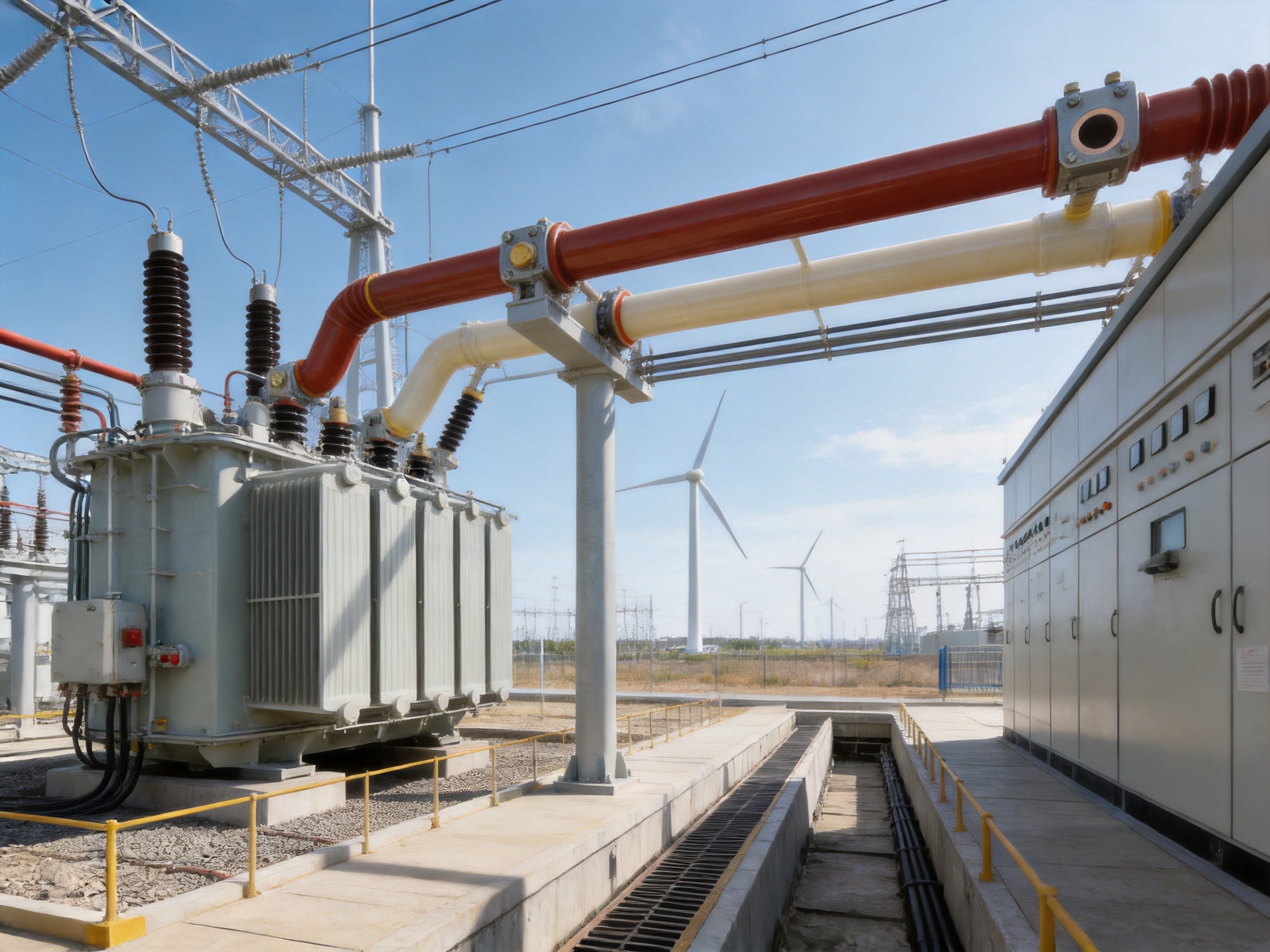
One of the most common applications is the connection between a main transformer and a low-voltage or medium-voltage switchgear lineup. The busbar can be routed directly from the transformer terminals to the control room or switch cabinet. This creates a clear connection path for high current and can reduce the visual and spatial complexity associated with multiple parallel cables.
Flexible terminal links allow the busbar to connect to transformer terminals and switchgear without imposing excessive mechanical force. The design can be fully insulated or configured according to the applicable project requirements. Proper coordination of phase identification, grounding, clearances, and equipment interfaces is essential.
Cable Trenches and Cable Mezzanines
The busbar may be routed through underground cable trenches or cable mezzanines to connect switchgear, transformers, and distribution equipment. This arrangement is useful where direct overhead routing is not practical or where the project requires a protected route beneath equipment rooms.
A fully insulated tubular busbar is particularly useful in crowded areas where conventional open conductors would require large clearances. It can also provide a more orderly route through a restricted space. Drainage, access covers, support spacing, ventilation, and moisture control must be included in the civil and electrical design.
Industrial Plants
Industrial plants often combine high current demand with dust, vibration, heat, chemical exposure, and restricted maintenance space. Steel mills, metallurgy facilities, petrochemical plants, cement works, mining operations, and manufacturing factories can benefit from an enclosed power transmission structure.
For industrial applications, the project team should evaluate chemical compatibility, surface contamination, fire risk, fault levels, mechanical vibration, and maintenance access. The external epoxy surface should be protected from impact during construction, and any field modifications should be approved by the manufacturer.
Renewable Energy Installations
Wind power and solar power facilities require reliable connections between generation equipment, transformers, switchgear, and collection systems. Wind turbines may experience vibration, temperature changes, limited access, and difficult transport conditions. Tubular busbars can be designed for compact routing and high-current transmission within or near turbine systems.
Solar and renewable energy substations may be installed in exposed areas with strong sunlight, wind, humidity, dust, and temperature variation. The fully insulated construction can reduce the effect of external contamination, while the grounding and shielding system supports controlled electrical behavior. Outdoor terminals and transition points must receive particular attention.
Rail Transit and Large Commercial Facilities
Rail transit systems, airports, hospitals, data centers, and large commercial buildings require dependable power distribution and strong fire safety performance. A compact insulated busbar route can reduce the space needed for high-current connections and help organize critical electrical rooms.
In facilities where service continuity is important, maintenance planning should include inspection of terminal joints, grounding points, support structures, and external insulation surfaces. The system should be integrated with the facility's fire protection, emergency power, monitoring, and grounding strategies.
9. Installation and Commissioning Considerations
Factory manufacturing improves consistency, but installation quality remains essential. The busbar route should be surveyed before delivery to confirm dimensions, equipment positions, support locations, access routes, and lifting arrangements. Each section should be checked against the packing list and approved drawings.
During handling, the cast insulation should not be dragged, dropped, or struck against structures. Lifting points specified by the manufacturer should be used. Terminal surfaces must remain clean and protected until connection. Temporary covers should be retained during storage and installation.
Supports must be installed at the approved spacing and aligned with the busbar centerline. The maximum suspended span should not exceed five meters unless a separate engineering calculation approves another arrangement. Excessive unsupported length can increase deflection and stress at terminal joints.
Grounding points must be connected securely to the site grounding system. Grounding leads should not be sharply bent, cut, or left exposed to standing water. Each grounding point should remain clearly marked and numbered. The metal shielding layer must have verified electrical continuity after installation.
Terminal conductor surfaces should be cleaned and prepared according to the manufacturer's instructions. Silver- or tin-plated surfaces should not be damaged by aggressive tools or unsuitable abrasives. Bolts must be tightened to the specified torque, and flexible links must be installed without twisting or excessive bending.
After installation, commissioning tests may include insulation resistance, phase identification, conductor continuity, grounding continuity, withstand testing, contact resistance, and visual inspection. Test results should be recorded as part of the project handover documentation. The system should not be energized until all protective covers, grounding connections, joint fasteners, and inspection requirements have been completed.
10. Maintenance and Service Life
The product is designed for a service life of more than 30 years under suitable operating and maintenance conditions. Some general product references describe an expected service period of 30 to 40 years. Actual service life depends on operating temperature, electrical loading, environmental exposure, mechanical conditions, installation quality, maintenance, and the performance of connected equipment.
Routine maintenance should include visual inspection of the external insulation, terminal joints, grounding connections, support structures, flexible links, bolts, and waterproofing components. Any cracks, impact marks, discoloration, corrosion, moisture ingress, unusual heating, or loose hardware should be investigated promptly.
Thermal imaging can help identify abnormal heating at joints and terminal connections while the busbar is operating under load. The inspection frequency should reflect the criticality of the installation and the severity of the environment. High-humidity, high-dust, coastal, chemical, and high-temperature installations may require more frequent inspection.
Grounding continuity should be checked periodically, particularly after maintenance work or modifications. Grounding points must remain accessible and identifiable. Where outdoor terminations use climbing devices or extended creepage structures, the surfaces should be checked for contamination and physical damage.
The insulation should not be drilled, cut, or modified without written approval from the manufacturer. Unauthorized modification may reduce dielectric strength, interrupt shielding, expose the conductor, or permit moisture ingress. If a section is damaged, the recommended solution is normally replacement or an approved repair procedure rather than improvised field treatment.
11. Customization and Engineering Support
Power transmission projects rarely have identical requirements. The busbar route may include different lengths, bends, elevation changes, transformer interfaces, switchgear connections, expansion points, and support arrangements. A professional manufacturer therefore needs to provide more than a standard product catalog.
WOPENG provides customized OEM solutions for insulated busbar and tubular busbar systems. Custom engineering may cover conductor material, conductor size, voltage level, insulation thickness, current rating, terminal type, flexible connection, shielding structure, grounding arrangement, outdoor protection, support accessories, route dimensions, and monitoring requirements.
To prepare an accurate technical proposal, the manufacturer typically needs the following information:
System voltage and rated current.
Short-circuit current and duration.
Number of phases and neutral or grounding requirements.
Transformer, generator, switchgear, or equipment terminal dimensions.
Route length, bends, elevations, and support positions.
Indoor, outdoor, trench, mezzanine, or suspended installation conditions.
Altitude, ambient temperature, humidity, wind, ice, pollution, and seismic conditions.
Required fire rating, enclosure class, and environmental protection.
Applicable national, international, utility, or project standards.
Required inspection, testing, certification, and documentation.
Engineering support should continue from initial selection through design confirmation, production, testing, delivery, installation guidance, and commissioning. This integrated approach reduces the risk of mismatched interfaces and helps ensure that the final busbar system performs as intended.
12. Company Manufacturing Strengths
Founded in 2018, Jiangsu Wopeng Power Technology Co., Ltd. is a specialized high-tech enterprise focused on the development and manufacture of high- and low-voltage busbar systems. Its product portfolio includes 35 kV epoxy resin vacuum-cast tubular busbars, low-voltage cast resin busways, copper and aluminum tubular busbars, wind power tubular busbars, compact busbar systems, and sliding contact line power supply systems.
The company serves power generation, substations, wind energy, industrial manufacturing, rail transit, and large commercial facilities. Its products operate across more than 17 provinces and multiple industrial sectors, supporting projects with different electrical, environmental, and installation requirements.
WOPENG's production capability includes vacuum casting systems, CNC machining equipment, and automated assembly technologies. These resources support the controlled manufacturing of conductor assemblies, insulation bodies, terminal connections, shielding layers, grounding components, and customized accessories.
The company maintains a team of engineers, technical specialists, and production professionals with experience in power equipment technology. A strict quality management system is used to organize raw material control, process inspection, final testing, and product documentation. High-voltage tests, insulation tests, mechanical verification, and routine quality checks are incorporated into the inspection process.
This combination of engineering expertise and manufacturing control is important because a tubular busbar is not simply a conductor covered with insulation. It is a complete electrical and mechanical system. Its performance depends on conductor design, resin processing, shielding, grounding, connection technology, support structure, installation conditions, and testing. A manufacturer capable of managing all these elements can provide more dependable project support than a supplier focused only on basic conductor fabrication.
13. Frequently Asked Questions
Q1: What is the main advantage of an epoxy resin casting tubular busbar?
The main advantage is its integrated structure. The conductor, insulation, shielding, and protective layers can be formed into a compact, nonseparable body. This provides strong electrical insulation, mechanical protection, moisture resistance, fire performance, and reliable operation in demanding environments.
Q2: Is the product suitable for medium-voltage systems?
Yes. The product is designed for medium-voltage and higher-voltage applications, including 10 kV and 35 kV systems. Higher-voltage designs may also be engineered, subject to insulation coordination, testing, and project-specific approval.
Q3: What conductor materials are available?
High-purity copper is specified for the described product, with copper content of at least 99.90 percent. Depending on the application, tubular busbar systems may also use aluminum or aluminum alloy conductors. The selection depends on current, weight, dimensions, short-circuit performance, cost, and installation requirements.
Q4: What is the service life?
The design service life stated for the product is more than 30 years under suitable operating conditions. Actual service life depends on loading, temperature, humidity, mechanical stress, installation quality, maintenance, and environmental exposure.
Q5: Can the tubular busbar be installed outdoors?
Outdoor installation is possible when the busbar, terminals, joints, sealing, grounding points, and support system are designed for outdoor conditions. Outdoor projects must consider solar radiation, wind, ice, rain, pollution, temperature, moisture, and ultraviolet exposure. The selected model and terminal arrangement should be confirmed with the manufacturer.
Q6: What is the maximum suspended span?
The supplied technical requirement specifies that the maximum suspension span should not exceed five meters. Actual support spacing should be determined from the approved mechanical calculation, considering weight, wind, ice, seismic forces, short-circuit forces, and installation conditions.
Q7: How are the joints connected to transformers and switchgear?
Connections between the busbar terminal joints and equipment are made through flexible links secured with bolts. The flexible connection helps accommodate alignment tolerances and reduces mechanical stress on transformer or switchgear terminals.
Q8: How is the busbar grounded?
Copper stranded or braided grounding wires are reliably welded to the metal shielding layer. Grounding points are connected to the site grounding system, protected against moisture, and identified with markings and numbers. Grounding continuity should be tested before energization and during scheduled maintenance.
Q9: Does the product require regular maintenance?
Yes. Although the integrated insulation reduces maintenance requirements compared with exposed systems, periodic inspection is still necessary. Maintenance should include visual checks, thermal inspection of joints, grounding continuity, support condition, bolt tightness, waterproofing, and signs of mechanical or electrical damage.
Q10: What information is needed for a quotation?
A quotation normally requires the voltage, current, short-circuit level, conductor material, route dimensions, terminal details, environmental conditions, support arrangement, installation location, required tests, and applicable standards. Complete drawings and equipment interface data help the manufacturer prepare an accurate design and price.
Q11: How does the product compare with cables?
A tubular busbar can provide a more compact and structured high-current route than multiple parallel cables. It may reduce the number of field terminations and simplify high-current equipment connections. Cables may remain preferable for highly flexible routes, long underground runs, or installations requiring frequent directional changes.
Q12: Can the product be monitored?
Yes. The supplied information refers to a tubular bus CNC monitoring system developed for unmanned intelligent monitoring of multiple technical data points. Monitoring functions should be defined according to the project, such as temperature, connection condition, grounding status, or other operational parameters.
14. Conclusion
Epoxy Resin Casting Tubular Bus Bar technology provides a reliable solution for high-current and medium-voltage power transmission where electrical insulation, compact construction, mechanical strength, fire performance, and environmental resistance are all important. Its greatest strength is the integration of the conductor, insulation, shielding, and protective layers into a carefully controlled molded structure.
Compared with open bare busbars, the product provides stronger protection against accidental contact and contamination. Compared with complex parallel cable installations, it can create a cleaner and more structured route for high-current connections. Compared with many flexible or lower-grade insulated busbar alternatives, epoxy resin casting offers high dielectric strength, rigid mechanical support, and strong long-term environmental protection.
The performance of the finished system depends on more than the resin itself. High-purity conductor materials, accurate terminal machining, embedded connection technology, reliable shielding, secure grounding, vacuum injection, high-temperature curing, electrical testing, and professional installation all contribute to reliability. The manufacturer's ability to combine these functions is therefore a key factor in product selection.
With automated dual-component vacuum casting, CNC machining, automated assembly, standardized inspection, third-party testing cooperation, and engineering customization, Jiangsu Wopeng Power Technology Co., Ltd. is positioned to provide insulated busbar and tubular busbar systems for substations, industrial plants, renewable energy facilities, transportation infrastructure, commercial buildings, and other critical power applications.
References
1. Product technical information for Epoxy Resin Casting Tubular Bus Bar, supplied for this article.
2. Technical data and environmental design conditions for vacuum epoxy resin cast tubular busbars, supplied by the manufacturer.
3. IEC 61439, Low-Voltage Switchgear and Controlgear Assemblies.
4. IEC 60840, Power Cables with Extruded Insulation and Their Accessories for Rated Voltages Above 30 kV.
5. IEC 62271 series, High-Voltage Switchgear and Controlgear.
6. UL 94, Tests for Flammability of Plastic Materials for Parts in Devices and Appliances.
7. GB/T 5582, Classification of Environmental Conditions and Pollution Levels for Electrical Insulation Applications.
8. Manufacturer quality-control procedures covering high-voltage testing, insulation testing, mechanical verification, conductor inspection, and routine product inspection.
Product: Epoxy Resin Casting Tubular Bus Bar




-
 +86-180 3625 3000
-
 admin@wpbusbar.com
-
 No. 8, Yanjin Road, Chengxi Industrial Park, Shanyang Town, Baoying County, Yangzhou City, Jiangsu Province, China
Copyright © Jiangsu Wopeng Power Technology Co., Ltd.
All Rights Reserved.
 Custom Insulated Bus Bar Manufacturer
Tubular Busbar System Factory