

 EN

 English
 русский
 Français
 Español
 عربى
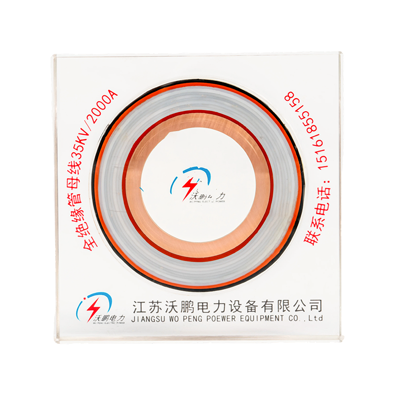
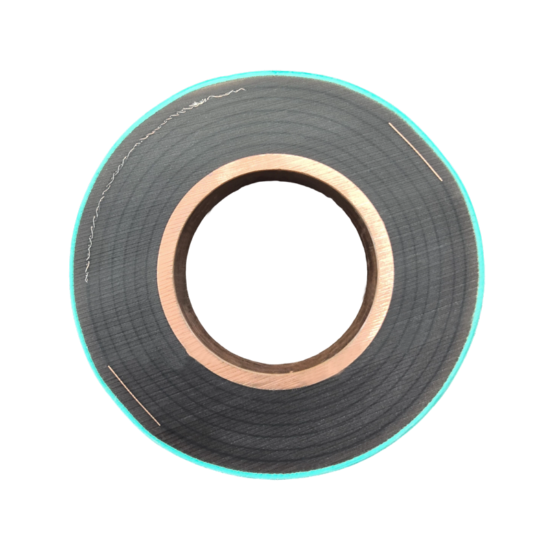
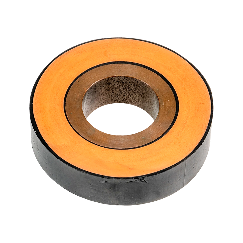
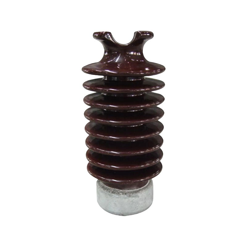
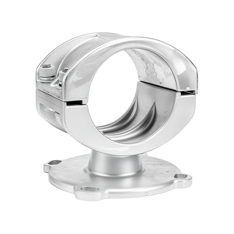
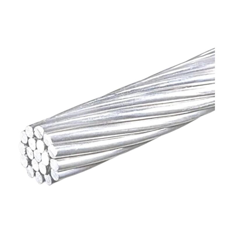
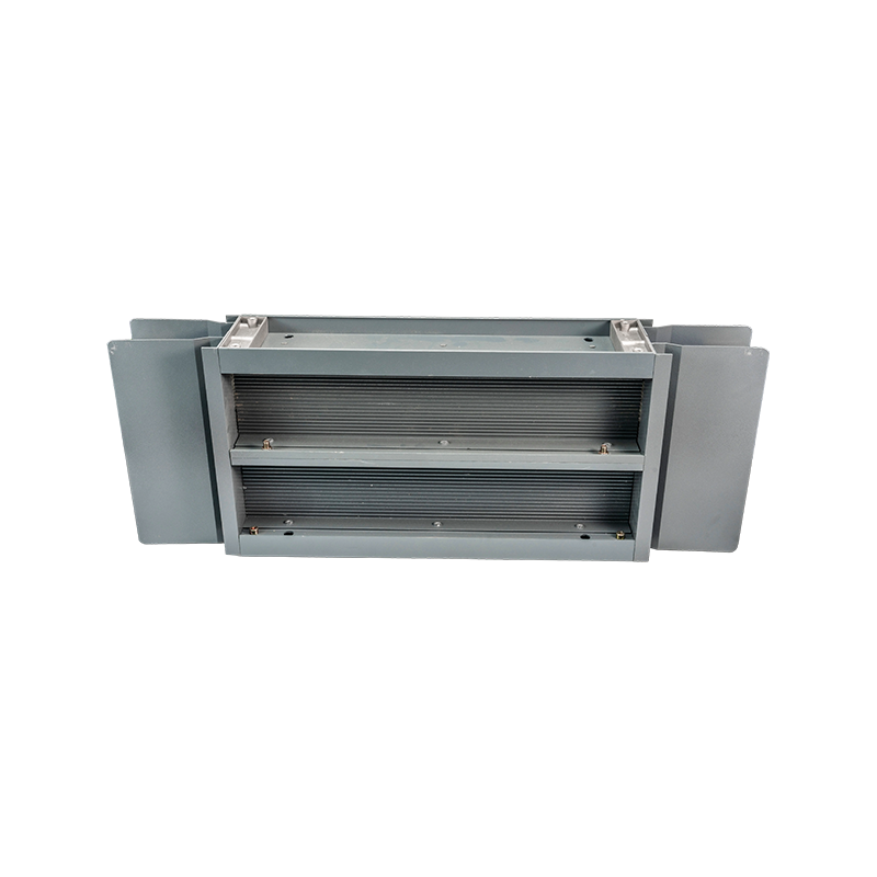
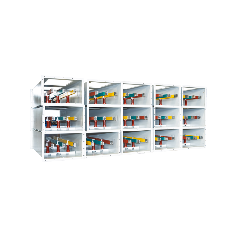

Ultra-High Voltage Magnesium-Aluminum Alloy Tubular Bus Bar: Design, Performance, Manufacturing, and Applications
Content
- 1 1. Understanding the Ultra-High Voltage Tubular Bus Bar
- 2 2. Material Technology and Alloy Selection
- 3 3. Tubular Geometry and Electrical Performance
- 4 4. Mechanical Advantages of the Tubular Structure
- 5 5. Manufacturing Process
- 6 6. Insulation and System Compatibility
- 7 7. Comparison with Conventional Busbar Materials
- 8 8. Environmental Resistance and Service Life
- 9 9. Applications
- 10 10. Quality Control and Testing
- 11 11. Manufacturing Strengths of Jiangsu Wopeng Power
- 12 12. Engineering and Procurement Considerations
- 13 13. Frequently Asked Questions
- 13.1 Q1: What is an ultra-high voltage magnesium-aluminum alloy tubular bus bar?
- 13.2 Q2: What voltage levels can the product serve?
- 13.3 Q3: Why use a magnesium-aluminum alloy instead of copper?
- 13.4 Q4: How does it compare with ordinary aluminum busbar?
- 13.5 Q5: Is the tubular conductor seamless?
- 13.6 Q6: What operating temperature can it withstand?
- 13.7 Q7: Can it be used outdoors?
- 13.8 Q8: Is it suitable for offshore wind power?
- 13.9 Q9: What is the expected service life?
- 13.10 Q10: What is the maximum support span?
- 13.11 Q11: Can the busbar be insulated?
- 13.12 Q12: What should buyers request from a manufacturer?
- 14 14. Conclusion
- 15 References
- 16 Product: Ultra-high Voltage Magnesium-Aluminum Alloy Tubular Bus Bar
Ultra-high voltage power systems require conductive equipment that can carry substantial current, withstand severe electrical and mechanical stresses, and maintain reliable performance over decades of operation. As transmission voltages increase, the requirements placed on busbar systems become more demanding. Conductors must manage high current density, limit temperature rise, control electric-field concentration, resist wind and vibration, and remain stable in outdoor environments exposed to moisture, salt fog, ultraviolet radiation, ice, and temperature cycling.
The ultra-high voltage magnesium-aluminum alloy tubular bus bar is designed to address these requirements through a combination of lightweight alloy construction, tubular geometry, controlled manufacturing, and specialized surface treatment. It is intended for high-voltage and ultra-high-voltage power transmission and transformation systems, including applications associated with 220 kV, 500 kV, 750 kV, ±800 kV, and 1000 kV systems. Depending on the project configuration, the product can be used in substations, generating plants, transmission connection points, industrial power distribution systems, renewable energy facilities, and other large-current electrical installations.
Jiangsu Wopeng Power Technology Co., Ltd. develops and manufactures busbar systems for high- and low-voltage applications. Its product portfolio includes epoxy resin vacuum-cast tubular busbars, low-voltage cast-resin busways, copper and aluminum tubular busbars, wind power tubular busbars, compact busbar systems, and sliding contact line systems. This broad product range gives the company practical experience in conductor design, insulation coordination, mechanical support, thermal management, assembly, and quality inspection.
This article examines the structure, material technology, manufacturing process, electrical and mechanical advantages, application value, quality considerations, and selection principles associated with ultra-high voltage magnesium-aluminum alloy tubular bus bars.
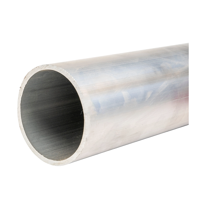
Ultra-high Voltage Magnesium-Aluminum Alloy Tubular Bus Bar
1. Understanding the Ultra-High Voltage Tubular Bus Bar
A tubular bus bar is a rigid electrical conductor manufactured in a hollow circular or similarly engineered cross-sectional form. Unlike a flat bar, the tubular structure provides a favorable balance between electrical capacity, mechanical stiffness, weight, and surface-area-to-volume ratio. In high-voltage systems, this geometry can also support more uniform electric-field distribution and efficient heat dissipation when properly designed and installed.
The ultra-high voltage magnesium-aluminum alloy tubular bus bar uses a specially formulated aluminum-based alloy containing magnesium and, depending on the required performance, other alloying elements such as manganese or rare-earth additions. The material is selected to provide a practical balance between electrical conductivity, strength, corrosion resistance, heat resistance, manufacturability, and service life.
Aluminum provides the primary advantage of low density and useful electrical conductivity. Magnesium and other controlled alloying elements can improve strength, corrosion behavior, and resistance to deformation. Rare-earth and heat-resistant alloy options can further improve the conductor’s stability when it operates at elevated temperatures or under demanding mechanical loads.
The product range may include 6063G aluminum-magnesium alloy, LF21Y aluminum-manganese alloy, 6R05 rare-earth aluminum alloy, and 2A14 heat-resistant aluminum alloy. Each material option can be matched to a different combination of conductivity, strength, temperature capability, span requirement, environmental exposure, and installation method.
1.1 Role in UHV Power Systems
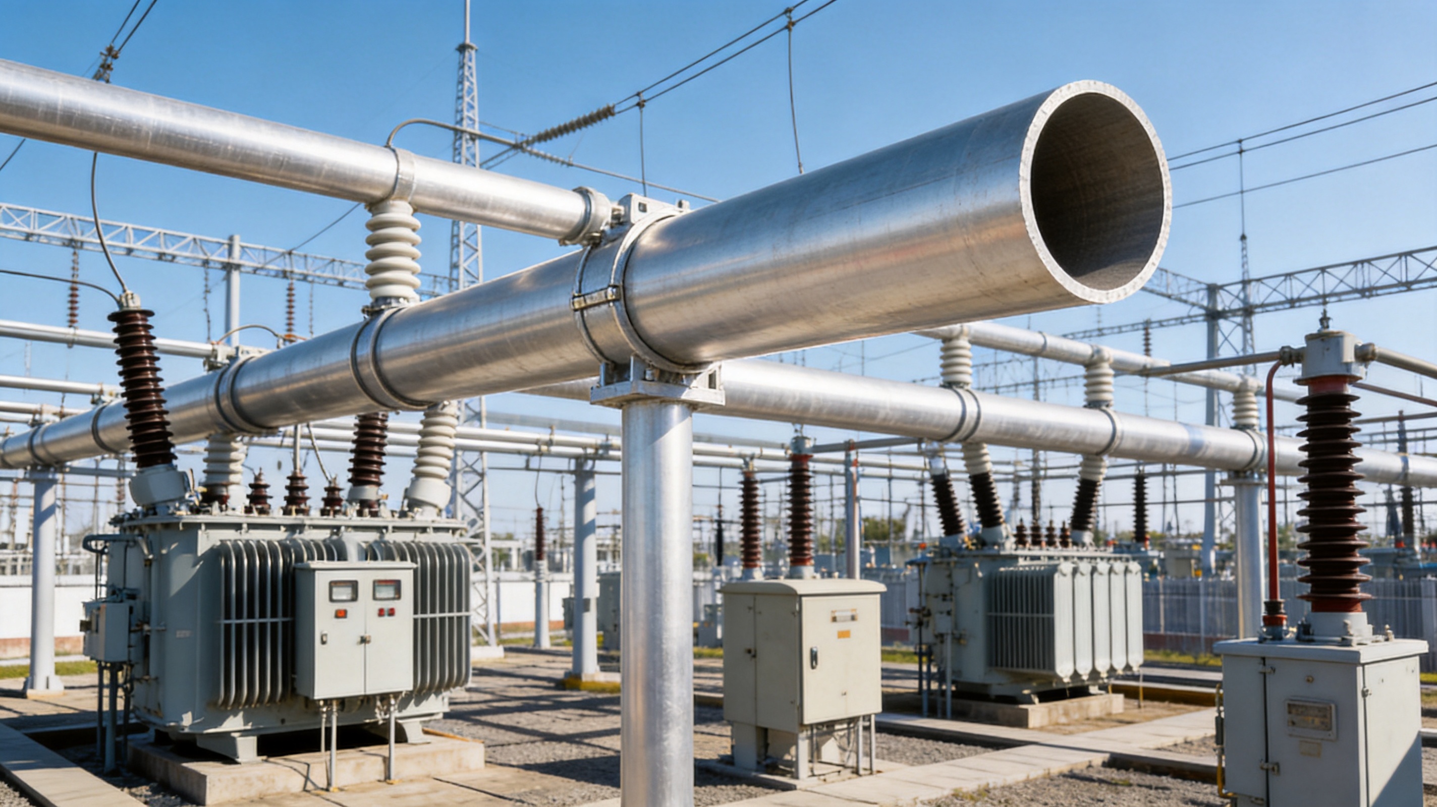
In an ultra-high voltage substation, tubular busbars may connect transformers, circuit breakers, disconnectors, instrument transformers, grounding equipment, and other primary electrical components. In a generating plant, they may form part of the connection between the generator step-up transformer and the high-voltage switchyard. In renewable energy installations, tubular busbars may support high-current collection and transformation systems where reduced weight and high mechanical stability are important.
The busbar is not simply a passive metal tube. It is part of a coordinated electrical and mechanical system. Its performance depends on the conductor material, diameter, wall thickness, support spacing, joint design, insulation or shielding arrangement, expansion provisions, clearances, grounding methods, and environmental protection measures.
1.2 Typical Performance Range
For suitable ultra-high voltage applications, products from a qualified manufacturer can be engineered for rated voltages from approximately 500 kV to 1000 kV, rated currents up to about 12,000 A, and working temperatures ranging from approximately -40°C to 150°C. Certain heat-resistant designs may operate at higher short-duration or specified continuous temperatures, subject to the complete system design and applicable standards.
Electrical conductivity may reach or exceed 60% IACS for selected material grades. Tensile strength can fall within an approximate range of 180 to 250 MPa, depending on alloy type and temper condition. These values are design references rather than universal guarantees; final performance must be confirmed through drawings, technical specifications, type tests, and project-specific verification.
2. Material Technology and Alloy Selection
The selection of an alloy for an ultra-high voltage tubular bus bar requires more than choosing the material with the highest nominal conductivity. A conductor that operates in a large outdoor substation must also withstand support reactions, thermal expansion, wind loading, transportation vibration, installation stress, and long-term corrosion exposure.
2.1 Aluminum-Magnesium Alloy
Aluminum-magnesium alloy is attractive because it combines relatively low density with improved mechanical strength compared with commercially pure aluminum. The reduced weight can simplify lifting and installation, reduce support loads, and lower the structural requirements of long-span arrangements.
Magnesium additions can also contribute to improved strength and favorable corrosion performance when the composition and processing conditions are properly controlled. However, alloying must be carefully managed because excessive alloying or inappropriate heat treatment can reduce conductivity or affect manufacturability. The objective is therefore to optimize the complete property set rather than maximize only one parameter.
2.2 Aluminum-Manganese Alloy
LF21Y aluminum-manganese alloy is one possible material option for applications requiring a dependable balance of conductivity, forming capability, corrosion resistance, and mechanical performance. It can be considered where stable tubular processing and outdoor durability are important.
2.3 Rare-Earth Aluminum Alloy
6R05 rare-earth aluminum alloy is intended for situations where improved material stability and enhanced resistance to demanding service conditions are required. Controlled rare-earth additions can influence grain structure, thermal stability, and mechanical behavior. The benefits depend on the alloy formulation, melting control, casting quality, and subsequent thermomechanical treatment.
2.4 Heat-Resistant Aluminum Alloy
2A14 heat-resistant aluminum alloy can be selected for installations in which elevated operating temperature, high current, or thermal cycling is a significant design factor. Heat-resistant formulations are useful when the conductor must maintain mechanical stability while carrying heavy current or operating in a high-temperature environment.
2.5 Balancing Conductivity and Strength
There is normally a trade-off between electrical conductivity and mechanical strength. Pure or highly conductive aluminum grades may provide excellent current-carrying performance but may not offer the mechanical properties required for long spans or severe weather conditions. Stronger alloys may provide better structural performance while having somewhat lower conductivity.
A professional design process considers current rating, allowable temperature rise, short-circuit forces, support spacing, wind and ice loads, seismic conditions, corrosion exposure, joint technology, and the required service life. The chosen alloy is then matched to the actual operating environment rather than selected by a single material index.
3. Tubular Geometry and Electrical Performance
The circular tubular form provides several advantages for high-current and high-voltage systems. The conductor’s outer surface can be engineered to support a more uniform electric-field profile than an irregular or poorly finished conductor. A larger effective diameter can also reduce surface electric-field intensity and help limit corona-related concerns when the system is correctly configured.
3.1 Current-Carrying Capacity
Current-carrying capacity depends on the alloy’s conductivity, conductor dimensions, ambient temperature, installation arrangement, emissivity, convection conditions, joint resistance, and permissible temperature rise. A tubular conductor can offer a favorable cooling surface, allowing heat generated by electrical resistance to be transferred to the surrounding air.
In outdoor substations, natural convection and radiation are important heat-removal mechanisms. The hollow internal space may also reduce material use without eliminating the required outer diameter and stiffness. This allows the designer to obtain a conductor with a high moment of inertia relative to its weight.
3.2 Reduced Power Loss
Electrical losses are affected by conductor resistance, operating current, joint quality, and temperature. Since power loss increases approximately with the square of current, even a modest reduction in resistance or operating temperature can create meaningful system benefits in high-current applications.
The magnesium-aluminum alloy tubular bus bar is designed to provide efficient current transmission while maintaining manageable temperature rise. Its low-loss performance is supported by appropriate conductor sizing, controlled material quality, smooth surfaces, reliable joints, and adequate heat dissipation.
3.3 Corona and Electric-Field Control
Ultra-high voltage systems require careful control of electric-field concentration. Sharp edges, irregular surfaces, poorly aligned joints, and contamination can increase local field intensity and contribute to corona, radio interference, audible noise, or insulation stress.
A tubular busbar with a consistent external surface and suitable diameter can contribute to more uniform field distribution. Where required, the complete system may include shielding rings, corona-control components, sealed joints, and carefully designed terminal connections. The conductor itself must be integrated with these components according to the project’s insulation coordination and high-voltage design requirements.
4. Mechanical Advantages of the Tubular Structure
Mechanical performance is especially important in outdoor substations and long-span busbar arrangements. The conductor can be exposed to wind pressure, ice accumulation, thermal expansion, electromagnetic forces during short circuits, transportation vibration, and seismic excitation.
4.1 High Specific Strength
Specific strength refers to strength relative to material density. A magnesium-aluminum alloy tubular conductor can provide a useful combination of lower weight and adequate strength. This may reduce the load imposed on insulators, support structures, foundations, lifting equipment, and connection hardware.
Lower weight can also simplify field installation. Fewer heavy lifting operations may be required, and longer sections may be handled more efficiently when the project’s transportation and safety conditions permit.
4.2 Bending and Vibration Resistance
The tubular profile has a high resistance to bending for its weight, particularly when the diameter and wall thickness are optimized. This is valuable for installations requiring relatively large support spans or where wind-induced vibration must be controlled.
The product is intended to support applications in demanding environments such as wind power facilities, rail transportation infrastructure, coastal substations, and high-altitude power stations. The actual span limit depends on conductor dimensions, support configuration, wind and ice calculations, allowable deflection, fittings, and local design codes. Under suitable conditions, a support span of up to approximately 8 meters may be achievable.
4.3 Seismic Performance
Seismic resistance is determined by the entire busbar assembly rather than the conductor alone. The alloy tube, supports, insulators, flexible connectors, expansion joints, and foundations must work together during an earthquake.
The relatively low mass of an aluminum-based tubular conductor can help reduce inertial forces. At the same time, adequate ductility, joint flexibility, and support design are essential. A reliable project solution should include seismic calculations and, where required, qualification testing or documented engineering verification.
5. Manufacturing Process
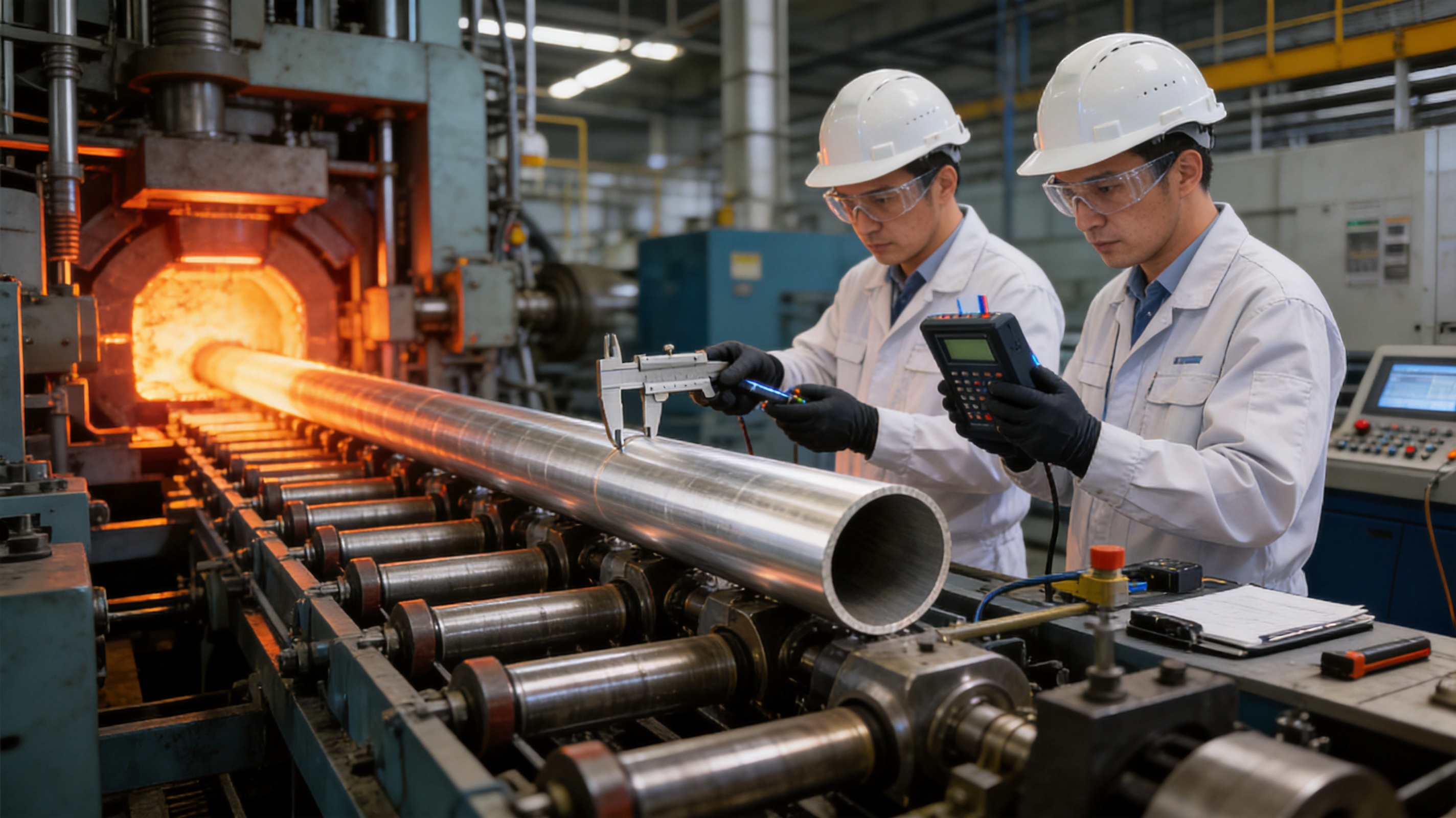
The performance of a tubular busbar depends heavily on manufacturing consistency. Alloy composition, casting quality, tube formation, heat treatment, cold drawing, dimensional control, surface finishing, and final inspection all influence electrical and mechanical behavior.
5.1 Raw Material and Alloy Preparation
Production begins with controlled alloy preparation. Aluminum and alloying elements are selected according to the required material grade and project specification. Chemical composition must be monitored to maintain consistent conductivity, strength, corrosion behavior, and processing response.
Impurities and inclusions can adversely affect fatigue performance, surface quality, and electrical reliability. For this reason, melting and refining procedures must be carefully managed before casting.
5.2 Horizontal Hot-Top Casting
Horizontal hot-top casting technology is used to support material purity and microstructural uniformity. A controlled casting environment helps regulate solidification, reduce defects, and produce a stable billet suitable for subsequent tube production.
Uniform microstructure is important because local variations can affect conductivity, tensile strength, elongation, corrosion behavior, and response to thermomechanical processing. Consistent billets form the foundation for consistent finished tubular products.
5.3 Transverse Piercing Hot Rolling
Transverse piercing hot rolling can produce seamless tube bodies without longitudinal weld seams. This is a major advantage in applications where continuity, mechanical integrity, and stable electrical performance are important.
Compared with a welded tube, a seamless tube avoids the potential weakness associated with a weld line and heat-affected zone. The process also supports the manufacture of larger tubular sections with a controlled wall structure, provided the piercing, rolling, and dimensional controls are properly implemented.
5.4 Thermomechanical Treatment
Thermomechanical treatment is used to adjust the material’s grain structure and mechanical properties. The heating, deformation, cooling, and aging conditions must be selected according to the alloy grade and final performance requirements.
Correct treatment can improve strength and stability while preserving acceptable conductivity. It can also help reduce residual stress and control dimensional changes during later processing and service.
5.5 Multipass Cold Drawing
Multipass cold drawing provides precise control over outside diameter, inside diameter, wall thickness, straightness, and surface quality. Drawing through a sequence of dies allows deformation to be distributed across multiple stages rather than concentrated in a single operation.
This process can improve dimensional accuracy and surface finish. It also enables the manufacturer to meet detailed installation requirements for support fittings, insulation systems, shielding components, and connection assemblies.
5.6 Surface Treatment
Surface treatment is an important part of product reliability. The outer surface may require cleaning, oxidation treatment, protective finishing, or other preparation depending on whether the conductor is used bare, shielded, insulated, or integrated into a cast-resin system.
Special oxidation treatment can improve compatibility between the aluminum alloy surface and insulating materials. It may help address adhesion challenges associated with epoxy vacuum casting or other insulation processes, supporting a tighter bond between the conductor and insulation layer.
5.7 Precision Machining and Assembly
End preparation, drilling, connection surfaces, flanges, supports, and accessory interfaces require precise machining. CNC equipment can be used to maintain dimensional repeatability and ensure that components align correctly during assembly.
Automated or standardized assembly procedures help reduce variation in joint preparation, fastening, insulation installation, and final inspection. These controls are particularly important where multiple busbar sections must be installed in a coordinated three-phase arrangement.
6. Insulation and System Compatibility
A tubular busbar may be used as a bare conductor in an air-insulated arrangement or combined with insulation and shielding technologies. In medium- and high-voltage applications, the busbar design must be coordinated with insulation clearances, creepage distances, partial discharge control, grounding, environmental sealing, and the characteristics of connected equipment.
6.1 Epoxy Vacuum Casting
Epoxy vacuum casting can be used to create a solid, compact, and mechanically stable insulated busbar assembly. Vacuum processing helps reduce voids and improve the consistency of the resin system around the conductor.
For this method to perform reliably, the alloy surface must be properly cleaned and treated. The thermal expansion behavior of the conductor and resin should also be considered. Good process compatibility helps reduce the risk of delamination, moisture ingress, partial discharge, and mechanical separation during temperature cycling.
6.2 PTFE Wrapping and Other Insulation Methods
PTFE wrapping and other engineered insulation methods may be used where chemical resistance, low friction, temperature stability, or specialized dielectric behavior is required. The selected insulation system depends on the voltage level, installation environment, thermal requirements, mechanical arrangement, and maintenance strategy.
The tubular busbar material must remain compatible with the selected insulation process. Surface preparation, dimensional tolerances, bending requirements, and connection design should be reviewed before production.
6.3 Environmental Sealing
Outdoor installations may require sealing against rain, condensation, dust, salt spray, and industrial pollutants. Sealed joints and properly designed end connections help maintain insulation performance and reduce corrosion risk.
For coastal and offshore wind projects, salt fog is a major concern. Materials, coatings, fasteners, gaskets, and drainage arrangements should be selected as a complete corrosion-control system rather than relying on the conductor alloy alone.
7. Comparison with Conventional Busbar Materials
Conventional copper busbars remain widely used because copper has high electrical conductivity and strong market acceptance. However, copper is significantly denser than aluminum alloys, which increases conductor weight and may increase the load on support structures. Ordinary aluminum busbars reduce weight but may not provide the same combination of strength, temperature capability, and structural performance required in certain ultra-high voltage or long-span applications.
| Characteristic | Magnesium-Aluminum Alloy Tubular Bus Bar | Traditional Copper Bus Bar | Ordinary Aluminum Bus Bar |
|---|---|---|---|
| Material density | Low to moderate, supporting lightweight design | High, resulting in greater structural load | Low |
| Electrical conductivity | High for selected alloy grades and dimensions | Very high | High, depending on grade |
| Mechanical strength | Improved through alloy design and treatment | Generally good, depending on grade | Varies by alloy and temper |
| Heat resistance | Available in heat-resistant alloy configurations | Good, subject to design and temperature | Varies significantly |
| Structural efficiency | High due to tubular geometry and low weight | Good, but with higher mass | Good in suitable applications |
| Corrosion resistance | Can be enhanced through alloy selection and surface treatment | Good in many environments, but may require protection | Generally favorable with suitable treatment |
| Installation handling | Relatively easy because of reduced weight | More demanding because of high density | Relatively easy |
| Typical design emphasis | UHV transmission, long spans, high current, harsh environments | High conductivity and established conventional systems | General power distribution and lighter-duty applications |
The comparison shows why the magnesium-aluminum alloy tubular design can be attractive for projects seeking a balance between conductivity, weight, mechanical stability, and high-voltage performance. It is not intended to replace every copper or aluminum busbar. Instead, it provides an engineered option for applications where the combined advantages of alloy technology and tubular geometry create greater system value.
7.1 Weight Reduction
Representative product comparisons may place the weight of an ultra-high voltage magnesium-aluminum alloy tubular busbar in the range of approximately 8 to 12 kg per meter, while a comparable traditional copper busbar may be around 25 to 30 kg per meter. Actual values depend on dimensions, wall thickness, alloy grade, accessories, and required current rating.
Lower conductor mass can reduce support reactions, simplify transportation, and improve installation efficiency. It can also be valuable when upgrading an existing substation where the original support structures have limited additional load capacity.
7.2 Performance Compared with Ordinary Aluminum
Ordinary aluminum busbars may offer low weight and acceptable conductivity, but they may not provide sufficient strength or thermal stability for every large-span or ultra-high voltage application. The use of magnesium, rare-earth, manganese, or heat-resistant alloy systems can improve the performance balance.
In addition, the seamless tubular structure can offer advantages over flat or welded designs in bending resistance, field distribution, surface consistency, and thermal dissipation.
8. Environmental Resistance and Service Life
Busbars installed outdoors may be expected to operate for 30 to 40 years under normal conditions when correctly designed, manufactured, installed, and maintained. Service life depends on the electrical duty cycle, environmental exposure, joint integrity, surface treatment, support conditions, inspection practices, and compliance with operating limits.
8.1 Corrosion Resistance
Aluminum-based alloys naturally form an oxide layer that contributes to corrosion resistance. Alloy composition and surface treatment can further improve durability. In industrial, coastal, and offshore locations, the system may require additional protective measures such as sealed connections, compatible fasteners, protective coatings, drainage, and regular inspection.
8.2 Salt Fog and Coastal Conditions
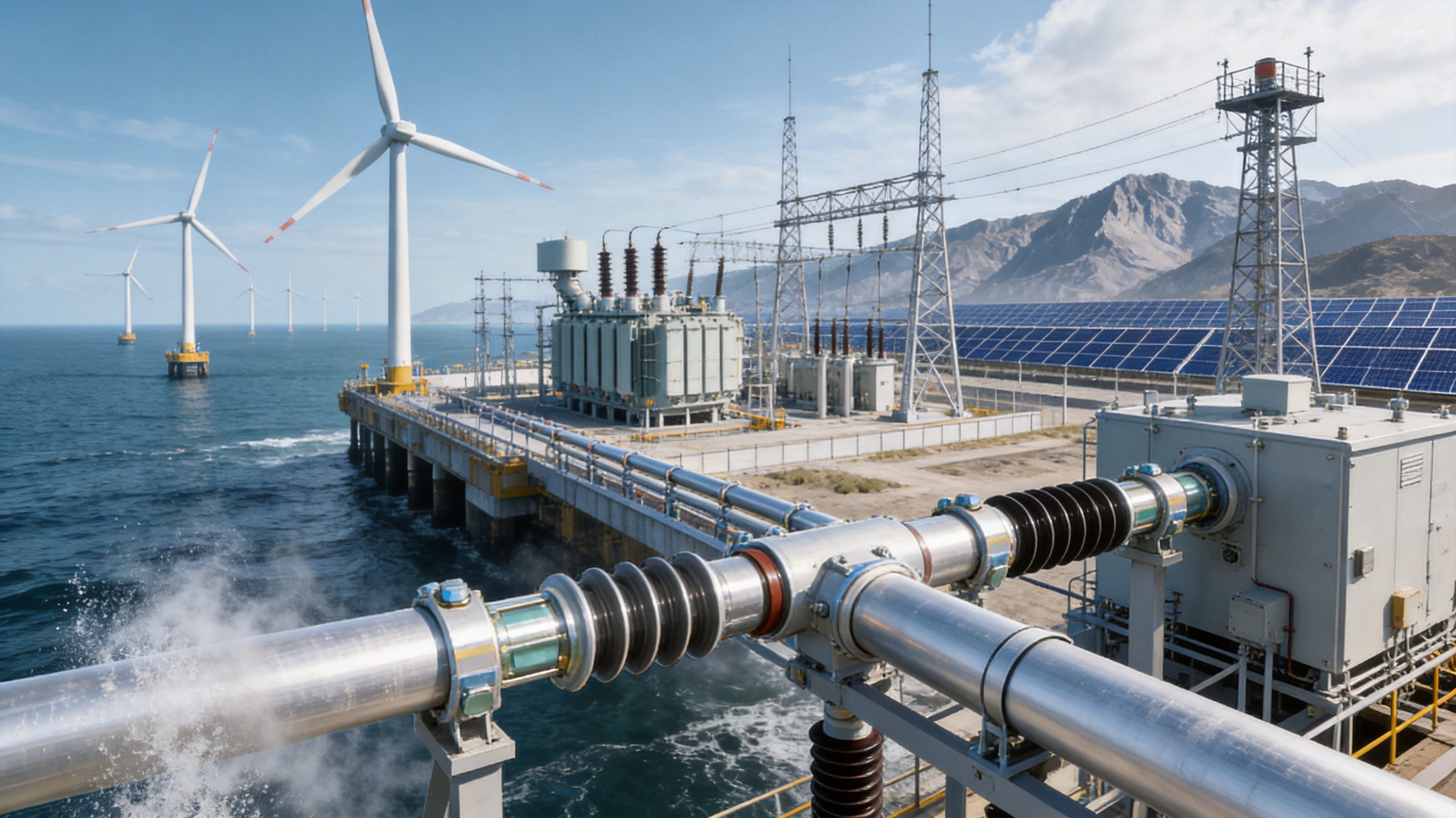
Salt contamination can increase surface leakage, accelerate corrosion, and affect insulation performance. For coastal substations and offshore wind power systems, the conductor and its accessories should be evaluated under salt-fog conditions.
The product’s corrosion-resistant alloy options and specialized surface treatments can help address these challenges. Nevertheless, environmental design must also consider insulator selection, washing requirements, enclosure design, joint sealing, and contamination classification.
8.3 Ice and Wind Loading
Ice accumulation increases conductor weight and aerodynamic loading. Wind can generate static pressure, vibration, and galloping behavior. A properly designed tubular busbar system must account for local wind speed, ice thickness, span length, support stiffness, temperature variation, and allowable deflection.
Ice-resistant surface treatment may help reduce ice adhesion, but it should be regarded as one part of a wider mechanical design. Support spacing and fittings remain critical to safe operation in cold and high-wind regions.
8.4 High-Altitude Operation
At high altitude, reduced air density affects insulation performance and heat dissipation. External insulation clearances may need correction, and thermal calculations may require additional consideration. The tubular busbar can be adapted to high-altitude applications through appropriate conductor dimensions, insulation coordination, surface treatment, and support design.
9. Applications
9.1 Ultra-High Voltage Substations
Substations operating at 500 kV and above require busbar systems that can connect major primary equipment while maintaining adequate clearances, current capacity, and mechanical reliability. Tubular conductors can be installed between transformers, circuit breakers, disconnectors, and other high-voltage apparatus.
The lower weight of a magnesium-aluminum alloy conductor can be beneficial in large switchyards with extensive busbar runs. Its strength and tubular profile can also support clean routing and reduced support density where engineering calculations permit.
9.2 Power Generation Plants
Hydropower, thermal power, wind power, and other generating facilities must transfer large currents from generators to transformers and grid connection equipment. A high-current tubular busbar can help maintain a compact and reliable connection system.
In generation facilities, operating temperature, electromagnetic forces, vibration, maintenance access, and connection reliability are important. Heat-resistant alloy options may be considered where current loading is high or available ventilation is limited.
9.3 Wind Power Systems
Wind power installations often involve vibration, fluctuating loads, limited maintenance access, and challenging weather conditions. Offshore wind farms add salt fog, humidity, strong wind, and difficult logistics.
A lightweight tubular busbar can reduce structural loading and facilitate installation. Its strength, corrosion protection, and insulation compatibility make it suitable for selected collector, transformer, and grid connection arrangements, subject to project-specific qualification.
9.4 Photovoltaic and Renewable Energy Facilities
Large photovoltaic facilities and renewable energy hubs may require high-capacity collection and transformation systems. Although many photovoltaic connections use lower-voltage equipment, the main collection and grid interface can involve substantial current and high-voltage equipment.
The tubular busbar can support compact layouts, reliable connections, and reduced structural weight. Its suitability depends on system voltage, current, environmental exposure, and the selected insulation arrangement.
9.5 Industrial Power Distribution
Metallurgical plants, chemical facilities, mining operations, and other large industrial installations often require high-current distribution under continuous and demanding operating conditions. These sites may also have corrosive atmospheres, high ambient temperatures, dust, vibration, and strict shutdown limitations.
A robust alloy tubular busbar can provide a durable connection between transformers, switchgear, furnaces, motors, and process equipment. Surface treatment and insulation selection should be matched to the specific industrial atmosphere.
9.6 Rail Transportation
Rail transit systems require reliable electrical distribution in environments subject to vibration, space restrictions, electromagnetic effects, and frequent operational cycles. Lightweight high-strength busbar designs may help reduce structural loads and support compact equipment layouts.
9.7 Specialized and Aerospace-Related Applications
Specialized electrical systems may place a premium on low weight, corrosion resistance, dimensional control, and thermal performance. The alloy tubular concept can be adapted for selected applications where the conductor’s mechanical and electrical characteristics are compatible with the relevant qualification requirements.
Such applications normally require additional validation, including vibration testing, thermal cycling, insulation testing, electromagnetic compatibility assessment, and verification of specialized installation conditions.
10. Quality Control and Testing
Quality control should cover the complete manufacturing chain from raw material receipt to final shipment. A reliable manufacturer should maintain documented procedures for material identification, alloy composition, casting, dimensional control, heat treatment, drawing, surface treatment, assembly, and inspection.
10.1 Material Testing
Material testing may include chemical composition analysis, tensile testing, conductivity measurement, hardness testing, elongation measurement, and metallographic examination. These tests verify that the alloy and temper condition are consistent with the technical specification.
10.2 Dimensional Inspection
Outside diameter, inside diameter, wall thickness, straightness, roundness, surface finish, and connection dimensions should be inspected using calibrated equipment. Dimensional consistency is essential for fitting, insulation processing, support installation, and electrical field control.
10.3 Electrical Tests
Electrical testing may include resistance measurement, dielectric withstand testing, insulation resistance testing, partial discharge assessment, temperature-rise testing, and high-voltage type testing when applicable. The test program should reflect the voltage level and final application.
10.4 Mechanical Verification
Mechanical verification may include tensile tests, bending tests, vibration evaluation, support-load testing, thermal expansion assessment, and verification of connection strength. For major UHV projects, mechanical calculations and qualification testing may be required for the complete busbar assembly.
10.5 Third-Party Validation
Testing collaboration with independent institutions can provide additional confidence in product safety and performance. Third-party testing is particularly valuable for type tests, high-voltage qualification, environmental durability, and project acceptance.
11. Manufacturing Strengths of Jiangsu Wopeng Power
Jiangsu Wopeng Power Technology Co., Ltd. was founded in 2018 as a specialized high- and low-voltage busbar system manufacturer. The company combines engineering development, material and process control, production, assembly, testing, and technical service.
Its product portfolio covers systems from low voltage to 35 kV, together with specialized tubular busbar products for wind power and other high-current applications. This experience is relevant to ultra-high voltage product development because reliable busbar engineering requires knowledge of conductor behavior, insulation, thermal management, structural support, electrical clearances, and installation conditions.
The company operates production lines equipped with vacuum casting systems, CNC machining equipment, and automated assembly technologies. Vacuum casting supports the manufacture of insulated busbar systems with controlled resin filling and reduced void risk. CNC machining supports accurate connection components and repeatable dimensional control. Automated assembly technologies can improve consistency and production efficiency.
Wopeng also applies standardized inspection procedures, including high-voltage tests, insulation tests, mechanical verification, and routine quality checks. Cooperation with third-party testing institutions provides independent validation for selected products and applications.
The company’s engineering and production teams include engineers, technical specialists, and manufacturing professionals experienced in power equipment technology. Its products operate across more than 17 provinces and major industrial sectors, supporting applications in power generation, substations, wind energy, industrial manufacturing, rail transit, and large commercial facilities.
For customers requiring customized tubular busbar systems, the company can evaluate current rating, voltage class, conductor material, dimensions, insulation type, environmental conditions, support span, joint design, and project-specific testing requirements. This type of technical coordination is important because a busbar should be engineered as part of the complete electrical installation rather than purchased as an isolated metal component.
12. Engineering and Procurement Considerations
12.1 Define the Electrical Duty
The first step is to establish rated voltage, rated current, short-circuit current, frequency, continuous load profile, permissible temperature rise, and expected overload conditions. These parameters determine conductor dimensions, alloy selection, support design, and insulation requirements.
12.2 Evaluate the Installation Environment
Designers should identify ambient temperature, altitude, humidity, pollution level, salt exposure, wind speed, ice loading, seismic intensity, ultraviolet exposure, and chemical contaminants. The environmental information determines surface treatment, sealing, insulation coordination, corrosion protection, and mechanical calculations.
12.3 Confirm Mechanical Layout
Support spacing, span length, conductor routing, expansion joints, connection points, lifting requirements, and allowable deflection should be reviewed before production. A maximum span of approximately 8 meters may be possible in suitable configurations, but the final span must be determined through engineering calculations.
12.4 Review Joint Design
Joints are among the most critical parts of a busbar system. They must provide low electrical resistance, adequate mechanical strength, reliable alignment, and resistance to environmental ingress. Contact surfaces, fasteners, surface treatments, torque requirements, and thermal expansion should all be specified.
12.5 Confirm Insulation Compatibility
Where epoxy vacuum casting, PTFE wrapping, or another insulation method is required, the conductor surface condition and dimensional tolerances must be compatible with the process. The insulation system should be reviewed for dielectric strength, partial discharge performance, thermal cycling, mechanical adhesion, and long-term environmental stability.
12.6 Require Documentation
Procurement documentation should include material certificates, dimensional inspection records, electrical test reports, mechanical test results, process records, installation instructions, maintenance recommendations, and applicable type-test documentation. Clear documentation supports project acceptance and future maintenance.
13. Frequently Asked Questions
Q1: What is an ultra-high voltage magnesium-aluminum alloy tubular bus bar?
It is a tubular electrical conductor made from a specially formulated aluminum-based alloy containing magnesium and, in some configurations, manganese, rare-earth elements, or heat-resistant alloying additions. It is designed for high-current and ultra-high voltage transmission and transformation systems.
Q2: What voltage levels can the product serve?
The product line is intended for applications ranging from high voltage to ultra-high voltage, including 220 kV, 500 kV, 750 kV, ±800 kV, and 1000 kV scenarios. The exact voltage capability depends on conductor dimensions, insulation coordination, shielding, installation configuration, and completed type testing.
Q3: Why use a magnesium-aluminum alloy instead of copper?
The primary advantages are lower weight, reduced structural loading, easier handling, and a useful balance of conductivity and mechanical strength. Copper remains highly conductive, but its higher density can increase transportation, support, and installation requirements.
Q4: How does it compare with ordinary aluminum busbar?
The magnesium-aluminum alloy tubular design can provide improved strength, better span capability, enhanced thermal stability, and stronger environmental adaptability compared with some ordinary aluminum designs. The actual advantage depends on the selected alloy, dimensions, processing condition, and project requirements.
Q5: Is the tubular conductor seamless?
The manufacturing process can use transverse piercing hot rolling to produce seamless tube sections. This avoids a longitudinal weld seam and its associated heat-affected zone, supporting consistent mechanical and electrical performance.
Q6: What operating temperature can it withstand?
Typical designs may operate from approximately -40°C to 150°C, while selected heat-resistant alloy configurations can support higher specified temperatures. The permitted temperature must be confirmed according to the alloy grade, continuous current, short-circuit duty, insulation system, and project specification.
Q7: Can it be used outdoors?
Yes. The product is suitable for outdoor substations, power plants, renewable energy facilities, and industrial systems when correctly designed with appropriate surface treatment, sealing, insulation, corrosion protection, and environmental calculations.
Q8: Is it suitable for offshore wind power?
It can be considered for offshore wind power because its lightweight construction, strength, and corrosion-resistant treatment can support demanding applications. Offshore use requires additional evaluation of salt fog, humidity, wind, vibration, access limitations, and maintenance conditions.
Q9: What is the expected service life?
With appropriate material selection, anti-corrosion treatment, correct installation, and routine maintenance, a service life of approximately 30 to 40 years may be achievable under normal UHV operating conditions. Actual life depends on the environment and operating duty.
Q10: What is the maximum support span?
A support span of up to approximately 8 meters may be possible in suitable designs. The final span must be determined by structural calculations considering conductor dimensions, wind, ice, seismic loads, temperature expansion, vibration, and allowable deflection.
Q11: Can the busbar be insulated?
Yes. The conductor can be integrated with insulation systems such as epoxy vacuum casting or PTFE wrapping, provided that the alloy surface, dimensions, thermal behavior, and treatment process are compatible with the selected insulation technology.
Q12: What should buyers request from a manufacturer?
Buyers should request material certificates, dimensional data, electrical and mechanical test reports, type-test documentation where applicable, quality-control records, installation instructions, environmental suitability information, and evidence of experience with comparable power projects.
14. Conclusion
The ultra-high voltage magnesium-aluminum alloy tubular bus bar is an engineered solution for power systems that require high current capacity, controlled electric-field performance, mechanical strength, reduced weight, and long-term environmental resistance. Its value comes from the combination of alloy design, seamless tubular construction, thermomechanical treatment, precision cold drawing, surface treatment, insulation compatibility, and system-level engineering.
Compared with heavy copper busbars, it can reduce structural and handling loads. Compared with ordinary aluminum busbars, it can provide a stronger balance of mechanical performance, thermal capability, and environmental durability. Its tubular geometry supports effective heat dissipation, bending resistance, and clean high-voltage installation when correctly dimensioned.
Jiangsu Wopeng Power Technology Co., Ltd. supports this product direction through experience in high- and low-voltage busbar systems, vacuum casting, CNC machining, automated assembly, standardized inspection, and application-oriented engineering. Its product range and manufacturing capabilities allow customers to evaluate customized solutions for substations, generating plants, renewable energy projects, industrial distribution systems, rail transit, and other critical infrastructure.
Successful application depends on selecting the correct alloy, confirming electrical and mechanical requirements, coordinating insulation and surface treatment, and validating the finished assembly through appropriate testing. When these factors are managed as an integrated design, the magnesium-aluminum alloy tubular busbar can provide a reliable and efficient foundation for modern high-voltage and ultra-high voltage power transmission systems.
References
1. International Electrotechnical Commission, High-Voltage Switchgear and Controlgear Standards, technical guidance for high-voltage equipment design and testing.
2. International Electrotechnical Commission, Power Installations Exceeding 1 kV AC, principles for insulation coordination, clearances, and installation safety.
3. Aluminum Association, Aluminum Standards and Data, material properties, alloy designation, and engineering reference data.
4. ASM International, Aluminum Alloy Processing and Properties, guidance on alloy composition, thermomechanical treatment, and performance evaluation.
5. IEEE Standards Association, Guides for Substation Bus Design, mechanical loading, thermal performance, and electrical coordination.
6. Manufacturer technical information for magnesium-aluminum alloy tubular busbars, including material specifications, manufacturing procedures, inspection requirements, and application data.
7. Manufacturer technical information for epoxy resin vacuum-cast busbar systems, insulation processing, high-voltage testing, and environmental qualification.
Product: Ultra-high Voltage Magnesium-Aluminum Alloy Tubular Bus Bar




-
 +86-180 3625 3000
-
 admin@wpbusbar.com
-
 No. 8, Yanjin Road, Chengxi Industrial Park, Shanyang Town, Baoying County, Yangzhou City, Jiangsu Province, China
Copyright © Jiangsu Wopeng Power Technology Co., Ltd.
All Rights Reserved.
 Custom Insulated Bus Bar Manufacturer
Tubular Busbar System Factory