

 EN
EN

 English
 русский
 Français
 Español
 عربى
عربى
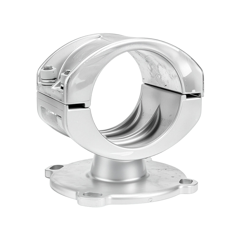
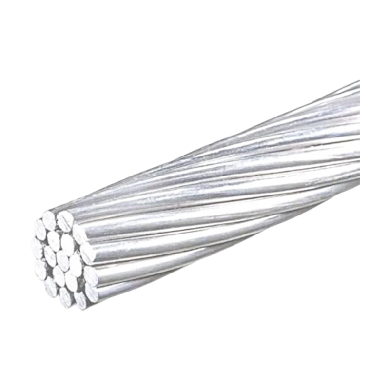
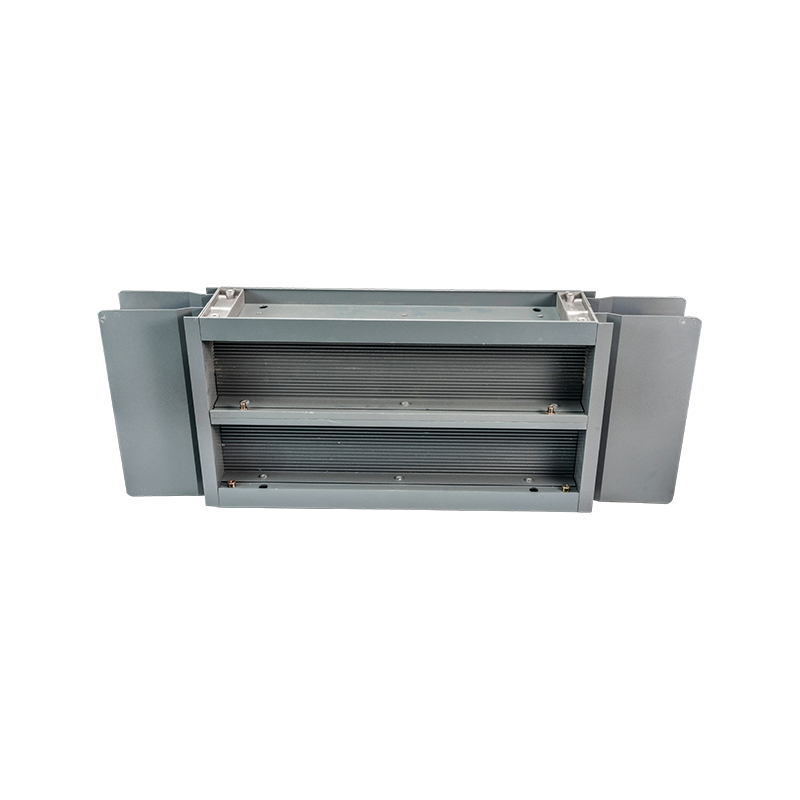
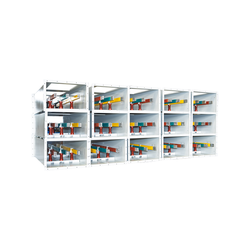


Ultra-High Voltage Magnesium-Aluminum Alloy Tubular Bus Bar: Design, Performance, Manufacturing, and Applications
Content
- 1 1. Understanding the Ultra-High Voltage Tubular Bus Bar
- 2 2. Material Engineering and Alloy Selection
- 3 3. Structural and Electrical Advantages of the Tubular Configuration
- 4 4. Electrical Field Control and Ultra-High Voltage Safety
- 5 5. Advanced Manufacturing Process
- 6 6. Quality Control and Testing
- 7 7. Comparison with Conventional Busbar Solutions
- 8 8. Environmental and Application Advantages
- 9 9. Insulation Compatibility and System Integration
- 10 10. Company Manufacturing Strengths
- 11 11. Installation, Commissioning, and Maintenance
- 12 12. Selection Guide for Project Engineers and Buyers
- 13 13. Frequently Asked Questions
- 13.1 Q1: What is the main benefit of a magnesium-aluminum alloy tubular bus bar?
- 13.2 Q2: Can the bus bar be used at 500 kV and above?
- 13.3 Q3: What current can the product carry?
- 13.4 Q4: Is the product suitable for outdoor installation?
- 13.5 Q5: Can it be used in offshore or salt-fog environments?
- 13.6 Q6: What insulation processes are compatible with the product?
- 13.7 Q7: Does a seamless tube provide an advantage over a welded tube?
- 13.8 Q8: What is the expected service life?
- 13.9 Q9: What is the maximum support span?
- 13.10 Q10: How should a buyer evaluate a manufacturer?
- 13.11 Q11: Can the product be customized?
- 13.12 Q12: How can energy losses be minimized?
- 14 14. Conclusion
- 15 References
- 16 Product: Ultra-high Voltage Magnesium-Aluminum Alloy Tubular Bus Bar
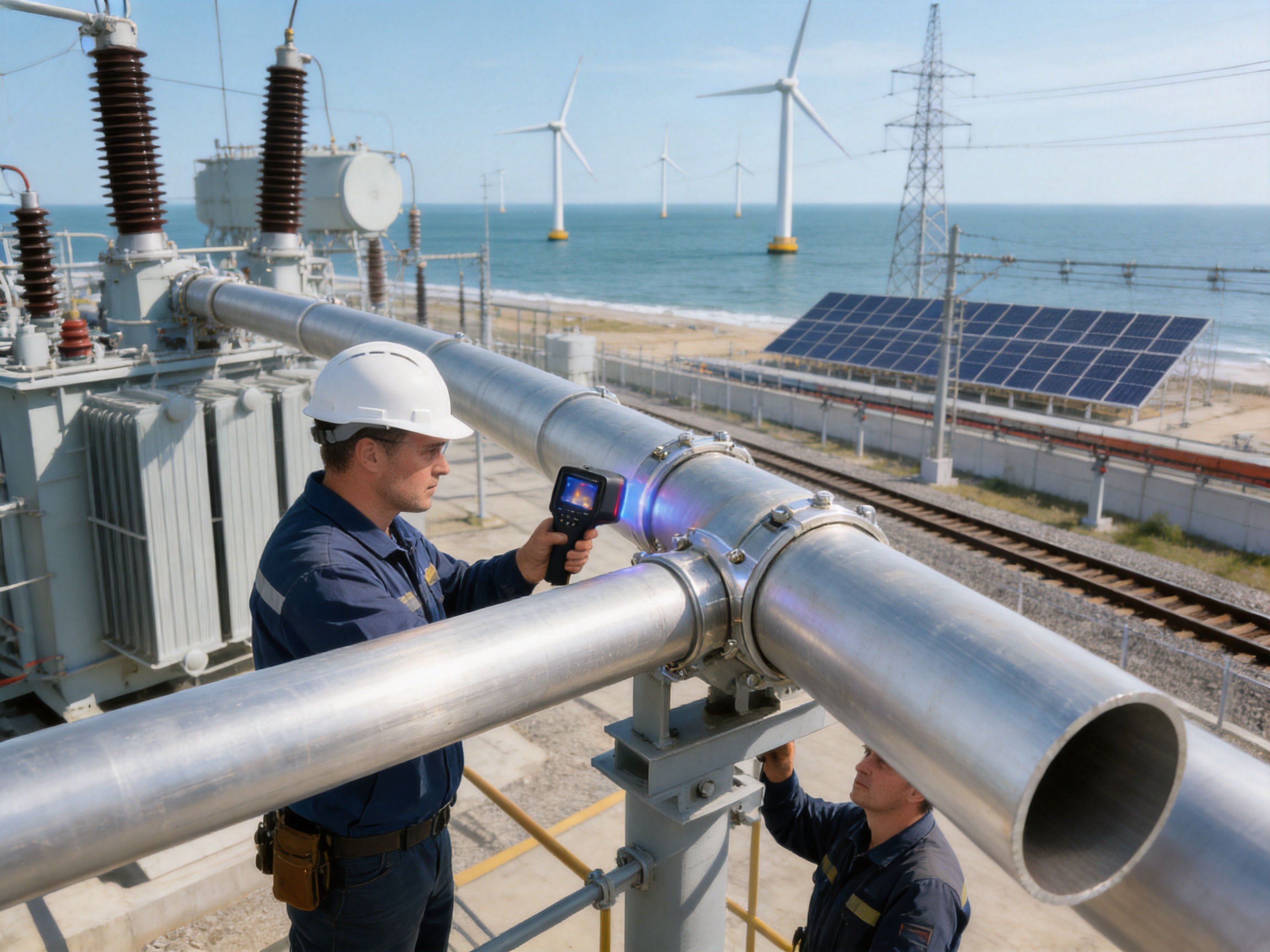
Ultra-high voltage power networks require conductive equipment that can carry very large currents while maintaining electrical stability, mechanical strength, thermal performance, and long-term outdoor reliability. As transmission voltages continue to increase, conventional solid conductors and traditional busbar arrangements can become difficult to install, support, cool, and maintain. Ultra-high voltage magnesium-aluminum alloy tubular bus bars provide an engineered alternative by combining the electrical advantages of aluminum-based conductors with improved strength, reduced weight, tubular structural efficiency, and carefully controlled surface and insulation compatibility.
The Ultra-high Voltage Magnesium-Aluminum Alloy Tubular Bus Bar described in this article is designed for demanding power transmission and transformation systems, including 220 kV, 500 kV, 750 kV, ±800 kV, and 1000 kV applications. Its material portfolio includes 6063G aluminum-magnesium alloy, LF21Y aluminum-manganese alloy, 6R05 rare-earth aluminum alloy, and 2A14 heat-resistant aluminum alloy. These material options allow the busbar system to be configured for different requirements involving conductivity, mechanical loading, temperature, corrosion resistance, span, and installation conditions.
Jiangsu Wopeng Power Technology Co., Ltd. develops and manufactures high- and low-voltage busbar systems for power generation, substations, wind energy, industrial facilities, rail transit, and commercial infrastructure. Its manufacturing capabilities include vacuum casting, CNC machining, automated assembly, inspection, and cooperation with independent testing institutions. By integrating alloy selection, seamless tube forming, thermomechanical treatment, surface engineering, and application-oriented design, the company provides a complete approach to ultra-high voltage tubular busbar development.
1. Understanding the Ultra-High Voltage Tubular Bus Bar
An ultra-high voltage magnesium-aluminum alloy tubular bus bar is a hollow conductive tube used to transmit and distribute high electrical currents in power generation, transmission, and transformation equipment. Unlike a flat strip conductor, a tubular bus bar uses a circular or engineered hollow cross-section to combine electrical conductivity with high bending stiffness and efficient heat dissipation. The tube can be installed as part of an open-air substation bus system, a power plant connection, a renewable energy collection system, or another high-current electrical arrangement.
The conductor is primarily manufactured from a magnesium-aluminum or other aluminum-based alloy. Aluminum provides a low-density conductive base, while magnesium, manganese, rare-earth elements, and heat-resistant alloying systems can be used to improve strength, structural stability, thermal capability, corrosion resistance, and process performance. The final alloy is selected according to the rated voltage, current, support span, ambient environment, installation method, and expected service life.
Ultra-high voltage systems place simultaneous demands on the conductor. The bus bar must carry current with limited resistance, withstand short-circuit forces, maintain sufficient clearance and insulation coordination, resist wind and ice loading, limit corona and radio interference, and remain stable during thermal cycling. A successful design therefore requires more than a highly conductive metal. It requires coordination between material science, tube geometry, electrical field control, structural engineering, manufacturing precision, and quality inspection.
1.1 Role in Modern Power Networks
In an ultra-high voltage substation, tubular bus bars may connect transformers, circuit breakers, disconnectors, instrument transformers, reactors, and transmission line terminals. In power plants, they can provide a high-current connection between generators, step-up transformers, switchgear, and grid interconnection equipment. In renewable energy installations, the bus bar may collect and transfer power from wind or photovoltaic generation assets to a larger transmission network.
The tubular configuration is especially valuable where high current must be transmitted across relatively long unsupported or widely supported sections. The conductor can provide a clean, stable geometry while reducing the number of structural supports compared with less rigid conductor arrangements. In the product information supplied, support spans of up to approximately 8 meters are identified for suitable designs. Actual span capability must always be confirmed through project-specific mechanical calculations, support configuration, conductor diameter, wind and ice loads, and applicable standards.
1.2 Typical Voltage and Current Requirements
The product family is intended to cover high-voltage and ultra-high voltage applications ranging from 220 kV to 1000 kV, including alternating-current and direct-current transmission scenarios where applicable. The supplied technical description identifies rated current capability up to 12,000 A, electrical conductivity of at least 60% IACS, a working temperature range from approximately -40°C to 150°C, and tensile strength in the range of 180 to 250 MPa for selected products.
These figures should be treated as representative product targets rather than universal values for every alloy, tube size, temper, and project configuration. Electrical and mechanical performance depends on wall thickness, outside diameter, alloy grade, heat treatment, joint design, surface condition, installation altitude, ambient temperature, and the required short-circuit duty. A qualified manufacturer should provide a project-specific datasheet, drawings, calculations, and test documentation before final selection.
2. Material Engineering and Alloy Selection
The main advantage of an aluminum-based tubular bus bar is its favorable balance between conductivity and weight. Copper offers excellent conductivity but has a much higher density, which increases transportation, lifting, support, and seismic loads. Ordinary aluminum is lighter, but its mechanical strength, high-temperature behavior, and environmental performance may not be sufficient for every ultra-high voltage application. Magnesium-aluminum and specially modified aluminum alloys are intended to address this balance.
2.1 6063G Aluminum-Magnesium Alloy
6063G aluminum-magnesium alloy is suitable for applications requiring a practical combination of conductivity, extrudability, surface quality, and structural performance. The magnesium-containing alloy system supports the production of accurate tubular sections and can be processed into components with a consistent surface finish. Depending on the required temper and manufacturing route, this material can be considered for busbar sections where weight reduction and stable mechanical properties are important.
2.2 LF21Y Aluminum-Manganese Alloy
LF21Y aluminum-manganese alloy is associated with improved forming characteristics and useful corrosion resistance. Manganese can contribute to strength and structural stability without creating the same density increase associated with copper-based alternatives. It may be selected for outdoor systems in which the conductor must maintain dimensional stability while exposed to moisture, temperature variation, wind, and pollution.
2.3 6R05 Rare-Earth Aluminum Alloy
Rare-earth aluminum alloy systems can be designed to refine grain structure, improve thermal stability, and enhance the consistency of mechanical performance. The 6R05 material specified for this product family is intended for demanding applications where the conductor must retain strength and dimensional stability under repeated thermal and mechanical loading. Rare-earth additions can also support more controlled microstructural behavior when combined with suitable casting, rolling, drawing, and heat-treatment processes.
2.4 2A14 Heat-Resistant Aluminum Alloy
2A14 heat-resistant aluminum alloy is intended for operating conditions in which the conductor may experience elevated temperature during continuous loading, overload, or short-duration system events. A heat-resistant alloy can help reduce the loss of mechanical strength associated with temperature rise. For a complete engineering assessment, the manufacturer should provide the allowable continuous temperature, emergency temperature, thermal expansion coefficient, conductivity after heat treatment, and expected mechanical properties at the specified operating temperature.
2.5 Balancing Conductivity and Strength
Alloy design involves trade-offs. Increasing alloying content may improve strength, heat resistance, or corrosion performance but can reduce conductivity if not carefully controlled. Conversely, maximizing conductivity may limit mechanical strength or thermal capability. The purpose of a specialized magnesium-aluminum alloy busbar is to optimize these properties together rather than selecting a material based on a single performance indicator.
For ultra-high voltage use, the alloy must also provide a consistent, smooth surface. Surface irregularities, inclusions, sharp edges, and dimensional deviations can affect electric-field distribution and increase the risk of corona. Metallurgical cleanliness and surface control therefore influence not only mechanical durability but also electrical performance.
3. Structural and Electrical Advantages of the Tubular Configuration
A tubular conductor has a high moment of inertia relative to its mass. This means it can resist bending and vibration efficiently without requiring the same quantity of material as a solid conductor of comparable stiffness. The hollow cross-section also provides a large external surface area for heat transfer, supporting natural convection and radiation from the conductor surface.
3.1 Lower Weight Compared with Copper
The lower density of aluminum-based alloys can significantly reduce the mass of long busbar sections. Reduced mass simplifies transportation, lifting, support design, and installation. It can also reduce the load transferred to substation steelwork, insulators, foundations, and seismic restraints. In regions with difficult access, elevated installation locations, or strict construction schedules, the weight advantage may produce meaningful project benefits.
Compared with traditional copper bus bars, the product information identifies a representative tubular busbar weight of approximately 8 to 12 kg per meter, while traditional copper bus bars are listed at approximately 25 to 30 kg per meter. The exact weight depends on diameter, wall thickness, alloy, and accessories. These values should be verified using approved project drawings rather than used as universal design values.
3.2 Efficient Heat Dissipation
Heat generated by current flow must be removed to prevent excessive temperature rise. The external cylindrical surface of a tubular bus bar promotes heat transfer by convection and radiation. The design can also be optimized for airflow, spacing, and surface emissivity. Lower temperature rise helps preserve joint performance, support insulation, surface treatments, and mechanical properties.
Thermal performance is affected by many variables, including current magnitude, frequency, conductor diameter, wall thickness, ambient temperature, solar radiation, wind speed, altitude, enclosure conditions, proximity effect, and connection resistance. A reliable design therefore uses thermal calculations or verified test data for the actual installation arrangement.
3.3 Reduced Electrical Losses
The bus bar is engineered to provide a large conductive area while maintaining controlled resistance. Reduced resistance can lower I²R losses during continuous operation. In high-current networks, even a small reduction in resistance can provide meaningful energy savings over the service life of the equipment. The supplied comparison describes the magnesium-aluminum tubular bus bar as having lower power loss than ordinary aluminum and traditional copper arrangements under the stated comparison conditions.
Loss performance should be evaluated across the entire system, including conductor sections, expansion joints, flexible connectors, terminals, contact surfaces, and transition components. A highly conductive tube can still experience unnecessary losses if joints are poorly designed, contact pressure is uneven, oxide layers are uncontrolled, or the system is not correctly aligned.
3.4 Improved Mechanical Stiffness
The circular tubular form resists bending, torsion, and vibration. This is important in outdoor substations and power plants exposed to wind, ice, thermal expansion, and short-circuit electrodynamic forces. A properly engineered tubular bus bar can support wider spans and reduce the quantity of intermediate supports, although support spacing must be calculated for each installation.
High tensile strength and bending resistance also support applications in wind power, rail transportation, and other environments where vibration or repeated mechanical movement may occur. The alloy, wall thickness, support arrangement, and joint configuration must be selected together to prevent local stress concentration and fatigue damage.
4. Electrical Field Control and Ultra-High Voltage Safety
At ultra-high voltage, electric-field control is a central design requirement. Uneven fields can produce corona discharge, audible noise, radio interference, ozone formation, energy loss, and long-term surface deterioration. Tubular conductors with smooth and appropriately sized surfaces can help distribute the electric field more uniformly than sharp-edged or poorly finished conductors.
4.1 Smooth Surface and Corona Control
Precision tube forming, cold drawing, machining, and surface treatment are used to control dimensional accuracy and surface quality. The absence of weld seams is particularly important where a continuous, smooth conductor surface is required. The supplied manufacturing approach uses transverse piercing hot rolling to produce seamless tubes, thereby avoiding the weakness and surface discontinuity associated with a welded seam.
Corona performance depends on conductor diameter, surface roughness, nearby components, altitude, humidity, contamination, voltage polarity, and the geometry of fittings. A complete ultra-high voltage system should therefore be evaluated through electric-field simulation, corona testing, and inspection of all transitions, clamps, terminals, and shielding components.
4.2 Full Shielding and Field Uniformity
The product description identifies a full shielding design intended to promote uniform electric-field distribution and suppress corona discharge. In practical systems, field grading may involve conductor geometry, shielding rings, smooth fittings, rounded transitions, insulated supports, and controlled clearances. These elements must be coordinated to prevent local field intensification.
For direct-current ultra-high voltage systems, polarity-specific field behavior, surface charge accumulation, and contamination effects require special consideration. For alternating-current systems, frequency, phase arrangement, spacing, and electromagnetic coupling also influence performance. Project engineers should confirm the relevant design criteria and test requirements for the intended network.
5. Advanced Manufacturing Process
The performance of an ultra-high voltage tubular bus bar depends heavily on manufacturing consistency. A carefully selected alloy can fail to meet expectations if it contains excessive inclusions, has inconsistent wall thickness, develops residual stress, or receives inadequate surface treatment. Jiangsu Wopeng Power Technology uses a process chain that combines material preparation, precision tube production, thermomechanical treatment, cold drawing, machining, assembly, and inspection.
5.1 Horizontal Hot Top Casting
Horizontal hot top casting is used to support high material purity and uniform microstructure. Controlled casting conditions help reduce segregation, porosity, inclusions, and other defects that could affect conductivity or mechanical strength. Stable temperature management and controlled solidification are important for creating a billet suitable for subsequent hot working.
Material traceability should be maintained from alloy preparation through finished product inspection. Records may include alloy composition, casting batch, billet identification, heat-treatment history, dimensional inspection, conductivity measurement, and mechanical test results. This traceability enables the manufacturer to investigate deviations and maintain consistent production across multiple orders.
5.2 Transverse Piercing Hot Rolling
Transverse piercing hot rolling forms a hollow billet without relying on a welded seam. During this process, a solid billet is heated and pierced to create the internal opening, followed by rolling operations that control diameter and wall thickness. Seamless production eliminates a longitudinal weld seam that could otherwise become a localized weakness or a source of surface irregularity.
The process requires accurate control of heating temperature, piercing conditions, rolling reduction, alignment, and cooling. Improper parameters can create eccentricity, wall-thickness variation, internal defects, or residual stress. Advanced production management and in-process measurement are therefore essential to ensure that the tube remains within specified tolerances.
5.3 Thermomechanical Treatment
Thermomechanical treatment combines controlled deformation and heat treatment to refine the microstructure and establish the desired balance of strength, ductility, conductivity, and thermal stability. The sequence may include homogenization, hot working, solution treatment, aging, stress relief, or other processes appropriate to the selected alloy.
For a high-voltage conductor, heat treatment must be repeatable. Excessive variation can lead to inconsistent mechanical properties between different tube sections. The manufacturer should control furnace temperature, holding time, atmosphere, cooling rate, and product loading. Test samples from representative batches can then verify that the required properties have been achieved.
5.4 Multipass Cold Drawing
Multipass cold drawing refines tube dimensions and improves surface quality. By reducing the tube gradually through several passes, the process can achieve closer control of outside diameter, inside diameter, wall thickness, straightness, and surface condition than a single aggressive reduction. Intermediate annealing or stress-relief operations may be introduced when required by the alloy and reduction schedule.
Cold drawing also affects residual stress and work hardening. These factors must be managed so that the finished tube retains dimensional stability during cutting, machining, assembly, and service. Accurate dies, mandrels, lubrication, drawing speed, and pass reduction are all important to product consistency.
5.5 CNC Machining and Component Preparation
CNC machining is used for precision preparation of ends, connection areas, mounting interfaces, transition components, and other custom features. Controlled machining helps maintain concentricity and dimensional accuracy at joints. It also allows the manufacturer to adapt the busbar to different substation layouts, equipment interfaces, support systems, and expansion requirements.
Machining must not introduce sharp edges, burrs, contamination, or excessive residual stress. For ultra-high voltage applications, edge treatment and surface finishing are especially important because small geometric irregularities can create localized electric-field concentration.
5.6 Surface Oxidation and Protective Treatment
Surface treatment improves corrosion resistance and supports compatibility with insulation systems. The supplied product description identifies special oxidation treatment designed to improve adhesion between the conductor and insulation materials such as epoxy resin and PTFE. A controlled surface promotes stable bonding and reduces the risk of delamination, void formation, or moisture ingress.
Surface treatment must be matched to the intended insulation process. Epoxy vacuum casting, PTFE wrapping, and other insulation technologies have different requirements for cleanliness, roughness, chemical compatibility, curing temperature, and adhesion. The manufacturer should verify the treatment through adhesion testing, thermal cycling, moisture exposure, and electrical insulation tests.
5.7 Vacuum Casting and Insulation Integration
Vacuum casting can reduce trapped air and moisture during the formation of an epoxy insulation layer. This is valuable because voids and inclusions may reduce dielectric strength and create partial discharge sites. When the conductor is used in an insulated tubular busbar system, the casting process must provide uniform coverage, consistent wall thickness, and reliable bonding.
Jiangsu Wopeng Power Technology has production capabilities involving vacuum casting systems, which also support its broader portfolio of epoxy resin vacuum-cast tubular busbars and low-voltage cast-resin busway products. The experience gained from these systems is relevant to insulation control, mold management, curing procedures, and routine electrical testing.
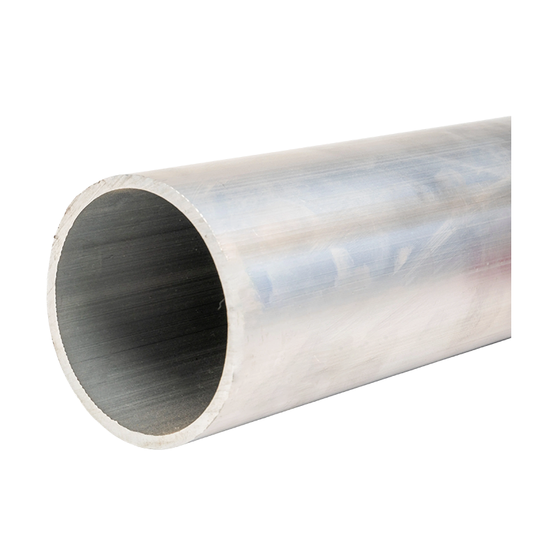
Ultra-high Voltage Magnesium-Aluminum Alloy Tubular Bus Bar
6. Quality Control and Testing
Ultra-high voltage busbar systems must be subjected to systematic quality control because defects may not be visible after installation. Inspection should begin with incoming raw materials and continue through casting, tube forming, treatment, machining, assembly, packaging, and final release.
6.1 Material and Dimensional Inspection
Material inspection may include chemical composition analysis, conductivity measurement, tensile testing, elongation testing, hardness testing, and metallographic examination. Dimensional inspection should cover outside diameter, inside diameter, wall thickness, straightness, ovality, surface roughness, end preparation, and joint interfaces.
For long tubular sections, measurement should be conducted at multiple positions. Localized wall-thickness variation or eccentricity can affect mechanical strength and electric-field distribution. Digital measurement systems, calibrated gauges, and inspection records provide better repeatability than visual inspection alone.
6.2 Mechanical Verification
Mechanical tests evaluate tensile strength, yield behavior, elongation, bending performance, vibration resistance, and, where applicable, fatigue performance. The test configuration should reflect the product's alloy, temper, wall thickness, and manufacturing condition. Support spans, connection loads, thermal expansion, and short-circuit forces should be considered in system-level mechanical calculations.
6.3 Electrical and Insulation Testing
Electrical testing may include resistance measurement, high-voltage withstand testing, insulation resistance testing, partial discharge testing, corona observation, and temperature-rise testing. The exact test program depends on whether the product is bare, shielded, epoxy insulated, or integrated into a complete busbar assembly.
Routine tests help identify production defects, while type tests demonstrate the performance of a representative design under more demanding conditions. For major power projects, buyers commonly request type-test reports, quality certificates, material certificates, inspection plans, and evidence of previous project applications.
6.4 Third-Party Validation
Cooperation with independent testing institutions can provide additional confidence in safety and performance. Third-party testing is useful for validating electrical insulation, thermal capability, mechanical strength, environmental resistance, and compliance with applicable technical standards. Independent reports can also support equipment approval by utilities, engineering contractors, and project owners.
Testing should be linked to the actual product configuration. A report for one diameter, alloy, insulation system, or voltage level may not automatically cover another design. The manufacturer and purchaser should confirm the scope, test conditions, acceptance criteria, and validity of each document.
7. Comparison with Conventional Busbar Solutions
The selection of a busbar material should consider the complete lifecycle rather than the purchase price alone. Copper, ordinary aluminum, and magnesium-aluminum alloy tubular bus bars each have different advantages. The most suitable option depends on current, voltage, environment, support structure, installation method, maintenance plan, and total cost of ownership.
| Busbar Type | Representative Weight | Mechanical Behavior | Thermal and Electrical Characteristics | Typical Voltage Position |
|---|---|---|---|---|
| Magnesium-aluminum alloy tubular bus bar | Approximately 8–12 kg/m for a representative design | High stiffness-to-weight ratio, strong bending and vibration resistance | High conductivity, efficient heat dissipation, low resistance when properly designed | High-voltage and ultra-high voltage systems, including selected 500 kV to 1000 kV applications |
| Traditional copper bus bar | Approximately 25–30 kg/m for a representative design | Very strong and highly conductive, but significantly heavier | Excellent conductivity and established connection technology | Widely used in high-current systems, with weight becoming a concern for long spans |
| Ordinary aluminum bus bar | Approximately 7–10 kg/m for a representative design | Lightweight, but mechanical capability depends strongly on alloy and geometry | Good conductivity and low density, with application limits under demanding conditions | Common in many high-voltage arrangements, subject to design conditions |
7.1 Advantages over Copper Bus Bars
The primary advantage over copper is lower mass. A lighter conductor requires less lifting equipment, reduces structural loading, and can simplify installation. In seismic regions, reducing suspended mass may help lower dynamic forces on supports and foundations. Lower density can also allow larger external diameters or alternative tubular geometries without creating an excessive total system weight.
Aluminum-based materials may also provide a favorable cost position when raw material, transportation, and installation are considered together. However, connection design is critical because aluminum oxide, thermal expansion, and galvanic interaction with dissimilar metals must be addressed through suitable joint materials, surface preparation, torque control, and sealing methods.
7.2 Advantages over Ordinary Aluminum Bus Bars
Compared with ordinary aluminum designs, an optimized magnesium-aluminum or special aluminum alloy can provide higher mechanical strength, improved resistance to vibration, better high-temperature stability, and a more favorable structural span capability. The seamless tubular form further improves stiffness and surface continuity.
These advantages can be important in coastal substations, high-altitude power stations, wind farms, rail transit systems, and other locations where wind, salt fog, vibration, or temperature cycling create additional stresses. The alloy does not eliminate the need for protective treatment, correct joint design, or periodic inspection, but it can provide a stronger foundation for the overall system.
7.3 Advantages over Welded Tubular Conductors
A seamless tube eliminates the longitudinal weld seam that may produce a localized mechanical or electrical discontinuity. Seamless manufacture can improve surface uniformity and reduce the risk that a weld-related defect will affect long-term performance. It is particularly valuable for conductors exposed to cyclic loading, high electric fields, or strict dimensional requirements.
Welded designs can still be suitable in certain applications when properly engineered and inspected. The relevant comparison should consider weld quality, heat-affected zones, nondestructive testing, surface finishing, fatigue behavior, and project standards. The seamless manufacturing route provides an additional reliability advantage where these factors are especially important.
8. Environmental and Application Advantages
The product is designed for use in severe outdoor and industrial environments. Its alloy composition, corrosion-resistant treatment, tubular geometry, and insulation compatibility allow it to serve applications beyond conventional indoor busbar installations.
8.1 Outdoor Substations
Outdoor substations expose busbars to rain, ultraviolet radiation, pollution, wind, temperature changes, and possible ice formation. The product's corrosion-resistant surface treatment and weather-resistant material system are intended to maintain stable performance under these conditions. Clearances, creepage distances, support insulation, drainage, and contamination levels must still be evaluated according to the site.
8.2 Salt Fog and Offshore Wind Power
Offshore and coastal projects create special risks because airborne salt can accelerate corrosion and reduce the surface insulation performance of contaminated equipment. A magnesium-aluminum alloy tubular bus bar with suitable protective treatment can help address these conditions. The final system should also use compatible fasteners, clamps, seals, and transition metals to minimize galvanic corrosion.
8.3 High-Altitude Power Stations
At high altitude, reduced air density lowers the dielectric strength of air and can affect corona inception, clearance requirements, cooling, and insulation coordination. A smooth tubular conductor with carefully engineered field control can support high-altitude application, but the design must be adjusted for the actual elevation, atmospheric pressure, pollution level, and temperature range.
8.4 Wind and Photovoltaic Power Systems
Renewable energy installations often require lightweight, mechanically stable, and corrosion-resistant conductors. Wind farms may experience continuous vibration, fluctuating current, and challenging access conditions. Photovoltaic plants may require long collection paths and outdoor equipment exposed to solar heating and weather. Tubular busbars can provide high current capacity with an efficient structural form for these applications.
8.5 Rail Transportation
Rail systems require reliable power transmission under vibration, movement, and limited installation space. The product's bending resistance, vibration performance, and weight reduction can support specialized rail power applications. The manufacturer should adapt insulation, joint design, support spacing, and environmental protection to the relevant railway standards and operating profile.
8.6 Industrial Power Distribution
Metallurgy, chemical processing, large manufacturing plants, and other industrial facilities may require high-current connections between generators, transformers, furnaces, motors, and switchgear. These locations can involve high ambient temperatures, dust, vibration, corrosive gases, and frequent load changes. A tubular busbar system can be configured to provide high current capacity, improved cooling, and controlled installation geometry.
9. Insulation Compatibility and System Integration
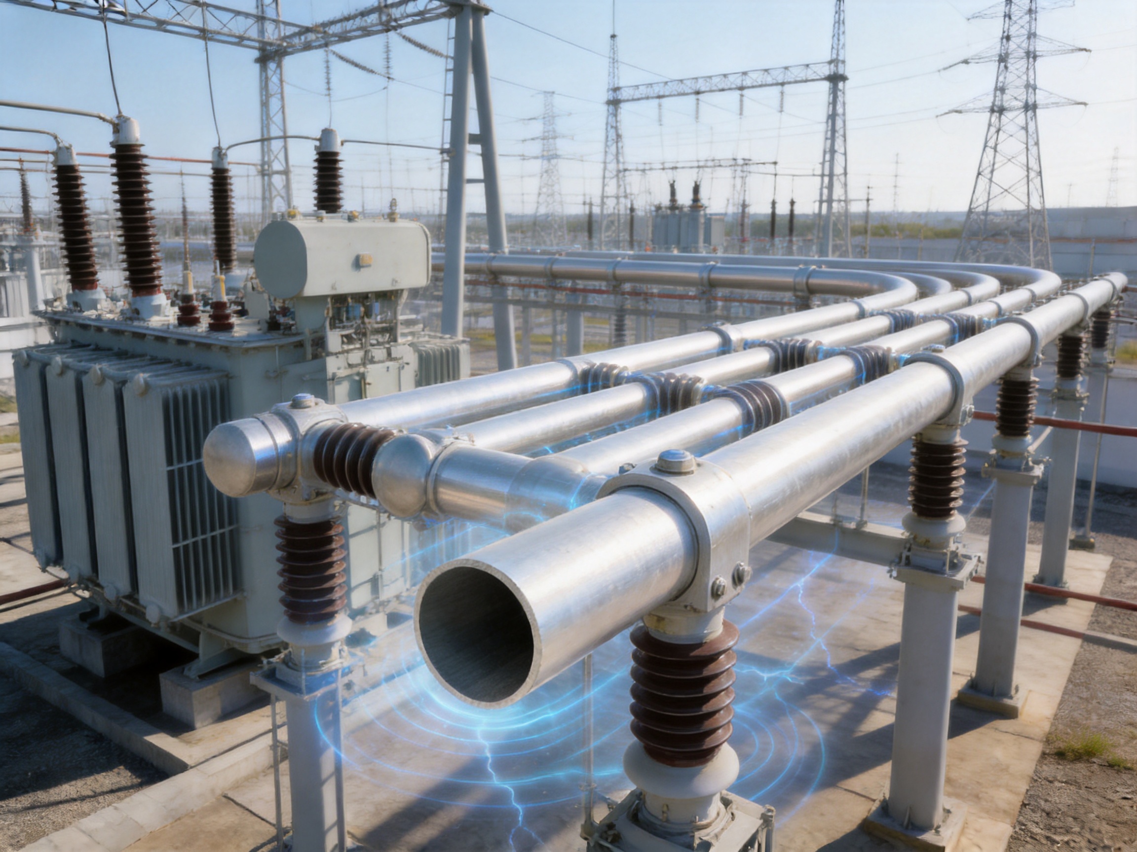
A conductor cannot be evaluated separately from its insulation and support system. In some installations, the tubular bus bar operates as an exposed conductor with air insulation and field-control components. In other designs, it is integrated with epoxy resin, PTFE, or another insulating layer. Each configuration requires a different approach to thermal expansion, partial discharge control, mechanical support, and maintenance.
9.1 Epoxy Vacuum Casting
Epoxy vacuum casting surrounds the conductor with a solid insulation system. Vacuum processing helps reduce air pockets, while controlled curing establishes a durable bond. The conductor surface must be clean and appropriately treated to achieve strong adhesion. The insulation thickness should be uniform and designed for the rated voltage, impulse withstand, thermal conditions, and environmental exposure.
9.2 PTFE Wrapping
PTFE wrapping can provide chemical resistance, low surface energy, and useful dielectric properties. However, the wrapping process must control overlaps, tension, wrinkles, gaps, and end termination. Surface treatment and mechanical protection may be required to ensure that the insulation remains securely attached during thermal cycling and vibration.
9.3 Thermal Expansion Management
Aluminum-based conductors expand and contract with temperature. The system must therefore include suitable expansion joints, sliding supports, flexible connectors, or other movement-management features. Rigidly fixing long busbar sections without considering thermal expansion can create excessive stress at supports, equipment terminals, and joints.
9.4 Joint and Connection Design
Joints are among the most important parts of a busbar system. They must provide low electrical resistance, adequate mechanical strength, controlled contact pressure, and long-term environmental protection. Aluminum surfaces require appropriate preparation because oxide films can increase contact resistance. Joint designs may include plated interfaces, specialized compounds, controlled fastening systems, flexible connectors, and sealed enclosures.
Connection hardware should be compatible with the conductor alloy and the surrounding environment. Dissimilar-metal contact should be assessed for galvanic corrosion. Torque values, contact surface condition, washer selection, and inspection intervals should be documented in the installation procedure.
10. Company Manufacturing Strengths
Jiangsu Wopeng Power Technology Co., Ltd. was founded in 2018 as a specialized high-technology enterprise focused on high- and low-voltage busbar systems. The company combines engineering, manufacturing, assembly, and quality-control capabilities to provide solutions for power generation, substations, wind energy, industrial manufacturing, rail transit, and large commercial facilities.
Its product portfolio includes 35 kV epoxy resin vacuum-cast tubular busbars, low-voltage cast-resin busways, copper and aluminum tubular busbars, wind power tubular busbars, compact busbar systems, and sliding contact line power supply systems. This breadth is significant because it gives the company experience across different voltage levels, insulation methods, conductor materials, installation environments, and customer requirements.
10.1 Engineering and Customization
Ultra-high voltage busbar projects rarely use a single universal configuration. Conductor diameter, wall thickness, alloy grade, support spacing, terminal geometry, insulation method, expansion arrangement, and surface protection may all need customization. A manufacturer with engineering capability can work from current ratings, voltage class, layout drawings, environmental conditions, and interface requirements to develop a project-specific solution.
Customization should include electrical calculations, thermal calculations, mechanical analysis, electric-field assessment, joint design, support design, and maintenance recommendations. The final documentation should clearly identify design assumptions and limitations so that the busbar system can be installed and operated correctly.
10.2 Modern Production Equipment
Modern vacuum casting equipment, CNC machining centers, automated assembly technologies, and standardized inspection stations support consistent product quality. Automation can improve repeatability in cutting, machining, insulation application, fastening, and assembly. It also helps reduce human variation in processes where dimensional accuracy and cleanliness are essential.
Production capability is strengthened when equipment is supported by documented procedures, calibrated instruments, operator training, preventive maintenance, and process records. Advanced equipment alone cannot guarantee product reliability; the manufacturing system must connect machinery, personnel, materials, inspection, and documentation.
10.3 Application Experience
The company reports that its products operate across more than 17 provinces and multiple industrial sectors. This application experience provides feedback on installation, transportation, environmental exposure, commissioning, maintenance, and customer requirements. Field experience can help identify practical issues that may not appear during laboratory design, such as access limitations, alignment challenges, support tolerances, or local environmental conditions.
For international and large-scale projects, buyers should request references that are technically comparable in voltage class, current rating, conductor size, insulation method, and environmental exposure. Application history is most valuable when the reference equipment has similar operating conditions to the proposed project.
11. Installation, Commissioning, and Maintenance
11.1 Transportation and Storage
Long tubular sections should be supported along their length during transportation and storage to prevent bending or local deformation. Protective packaging should prevent impact, contamination, moisture accumulation, and surface damage. Machined ends, insulation surfaces, and connection areas require additional protection.
Storage areas should be clean, dry, and level. Tubes should not be dragged across abrasive surfaces. If the product includes insulation or surface treatment, it should be protected from ultraviolet exposure, chemicals, excessive humidity, and temperatures outside the manufacturer's specified range.
11.2 Alignment and Support Installation
Supports and insulators must be installed according to approved drawings. Alignment errors can transfer stress to joints and equipment terminals. The installation team should verify centerline, elevation, support spacing, clearances, phase spacing, and expansion gaps before final tightening.
Support hardware should be tightened using calibrated tools and specified procedures. Excessive tightening can damage insulation or distort the tube, while insufficient tightening can lead to vibration, contact heating, or movement during a fault event.
11.3 Electrical Commissioning
Before energization, commissioning may include visual inspection, insulation resistance testing, high-voltage withstand testing, continuity testing, joint resistance measurement, phase identification, grounding verification, and partial discharge or corona checks where applicable. The commissioning plan should follow the approved design, relevant standards, and project acceptance criteria.
Any abnormal noise, odor, temperature, discharge indication, or resistance reading should be investigated before the system is placed into service. Records should include test instruments, calibration status, test conditions, measured values, and responsible personnel.
11.4 Maintenance During Service
Maintenance requirements depend on whether the system is bare, shielded, or insulated. Outdoor exposed systems may require periodic inspection for corrosion, contamination, loose hardware, ice accumulation, surface damage, and abnormal discharge. Insulated systems may require checks for cracking, tracking, moisture ingress, partial discharge, and abnormal temperature.
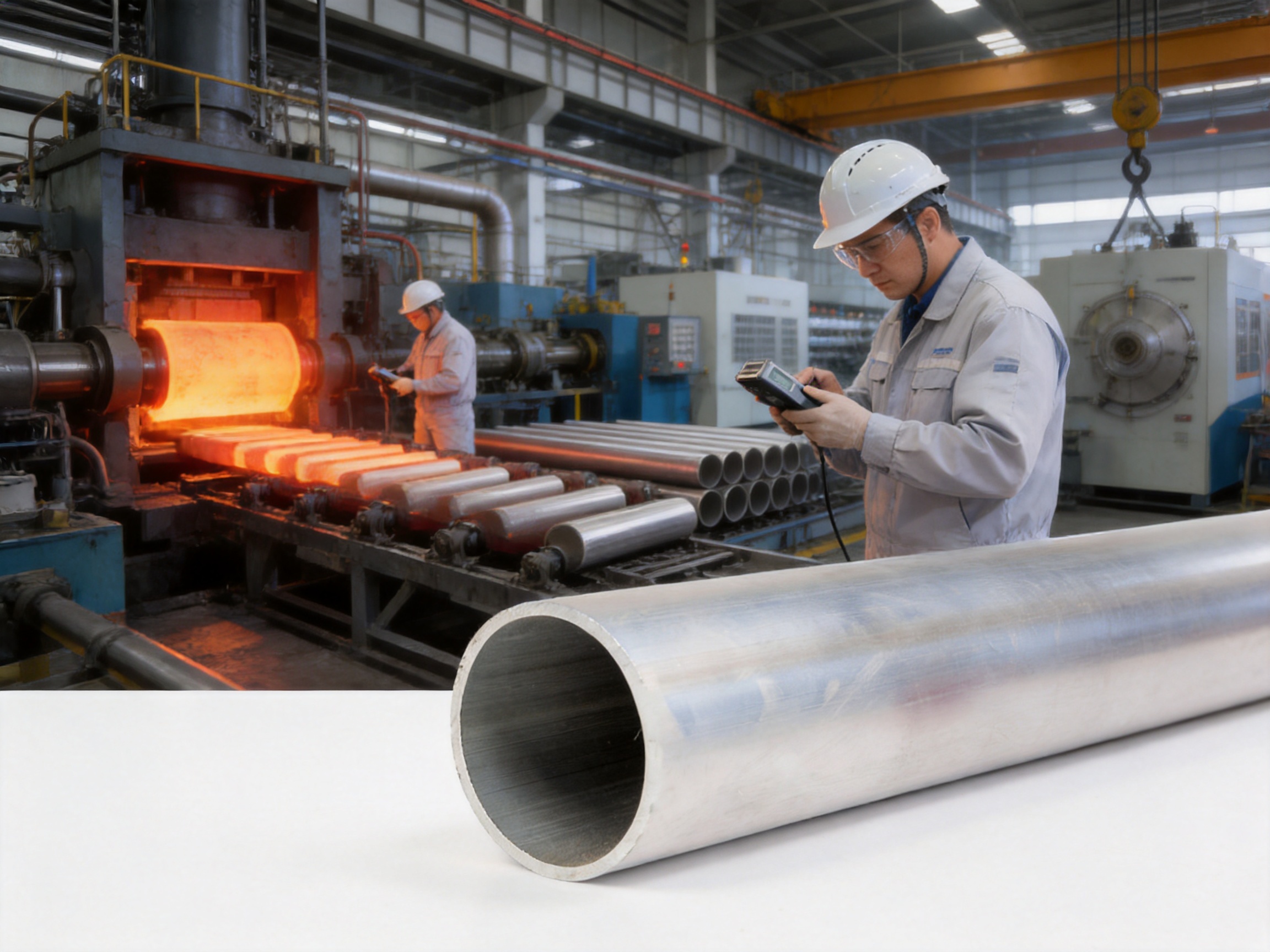
Thermal imaging can help identify high-resistance joints or localized overheating. Visual inspection can identify mechanical displacement, damaged coatings, contamination, and loose supports. Maintenance intervals should reflect the environment, load profile, fault duty, pollution level, and criticality of the installation.
12. Selection Guide for Project Engineers and Buyers
Selecting the correct tubular bus bar begins with a complete technical specification. The buyer should provide rated voltage, rated current, system frequency or direct-current conditions, short-circuit current and duration, installation altitude, ambient temperature, wind and ice loads, pollution level, corrosion exposure, support span, insulation arrangement, and connection interfaces.
12.1 Define Electrical Requirements
Rated current determines the required conductive area and thermal design. Short-circuit current determines electrodynamic forces and thermal stress. Voltage class determines clearances, insulation coordination, field control, shielding, and test requirements. Harmonic currents, load cycles, and emergency operating conditions may also affect conductor temperature.
12.2 Define Mechanical Requirements
Mechanical design should consider dead weight, wind, ice, seismic acceleration, thermal expansion, vibration, support spacing, lifting conditions, and equipment terminal loads. The selected alloy and tube geometry must resist these forces with appropriate safety factors. Where the busbar crosses long spans, structural calculations should be reviewed together with support and insulator suppliers.
12.3 Define Environmental Requirements
Coastal salt fog, industrial pollution, high altitude, desert dust, low temperature, heavy icing, and high humidity can each influence material and insulation selection. Protective treatments, seals, drainage, creepage distance, and inspection intervals should be adjusted to suit the location.
12.4 Review Documentation
A responsible manufacturer should be able to provide product drawings, material certificates, process information, inspection plans, test reports, installation instructions, maintenance recommendations, and quality records. For customized products, the documentation should clearly identify the approved revision and the relationship between drawings, calculations, and test results.
13. Frequently Asked Questions
Q1: What is the main benefit of a magnesium-aluminum alloy tubular bus bar?
The main benefit is the combination of low weight, good electrical conductivity, high structural stiffness, efficient heat dissipation, and improved mechanical performance compared with many conventional busbar arrangements. The tubular form also supports field control and can reduce support requirements when correctly engineered.
Q2: Can the bus bar be used at 500 kV and above?
Yes. The product family is intended for high-voltage and ultra-high voltage applications, including 500 kV, 750 kV, ±800 kV, and 1000 kV scenarios. The final design must be confirmed through voltage-specific electrical-field analysis, insulation coordination, type testing, and project approval.
Q3: What current can the product carry?
Selected designs are described as supporting rated currents up to approximately 12,000 A. Actual current capacity depends on alloy, conductor dimensions, ambient temperature, installation arrangement, allowable temperature rise, cooling conditions, and connection design.
Q4: Is the product suitable for outdoor installation?
Yes. The product is designed for outdoor use and is described as having corrosion resistance, weather resistance, ice-resistant surface performance, and stable operation over a wide temperature range. Outdoor suitability still requires correct protection, clearances, drainage, joint sealing, and environmental evaluation.
Q5: Can it be used in offshore or salt-fog environments?
It can be considered for offshore wind power and coastal substations when the alloy, surface treatment, fasteners, insulation, and sealing system are selected for salt-fog exposure. A project-specific corrosion protection plan is recommended.
Q6: What insulation processes are compatible with the product?
The product is described as compatible with epoxy vacuum casting and PTFE wrapping, among other insulation processes. Surface oxidation treatment can improve adhesion between the conductor and insulation. The selected process should be validated through adhesion, thermal, moisture, and electrical tests.
Q7: Does a seamless tube provide an advantage over a welded tube?
A seamless tube avoids a longitudinal weld seam and can provide more uniform mechanical and surface characteristics. This may improve reliability under high electric-field, vibration, and cyclic-loading conditions. The specific advantage depends on manufacturing quality and the requirements of the application.
Q8: What is the expected service life?
With suitable anti-corrosion treatment, correct installation, and normal operating conditions, the supplied product information indicates an expected service life of approximately 30 to 40 years. Actual service life depends on load, environment, maintenance, fault exposure, insulation condition, and joint performance.
Q9: What is the maximum support span?
A maximum support span of up to approximately 8 meters is identified for suitable designs. The permitted span must be confirmed through calculations based on conductor dimensions, alloy, wind, ice, seismic loading, short-circuit forces, support type, and allowable deflection.
Q10: How should a buyer evaluate a manufacturer?
Buyers should review relevant type-test reports, material traceability, manufacturing capabilities, inspection procedures, project references, engineering support, quality certifications, installation documentation, and after-sales service. Comparable experience at the required voltage and current level is especially important.
Q11: Can the product be customized?
Yes. Customization may include alloy selection, tube diameter, wall thickness, length, end machining, insulation method, surface treatment, connection hardware, support arrangement, and system layout. The manufacturer should approve the design through electrical, thermal, mechanical, and insulation calculations before production.
Q12: How can energy losses be minimized?
Losses can be reduced through adequate conductive area, high-quality alloy, smooth current paths, low-resistance joints, correct contact pressure, efficient heat dissipation, and suitable system spacing. Joint inspection and thermal monitoring are important throughout the service life.
14. Conclusion
The Ultra-high Voltage Magnesium-Aluminum Alloy Tubular Bus Bar is a specialized solution for power transmission and transformation systems that demand high current capacity, low weight, strong mechanical performance, controlled electric fields, and long-term environmental reliability. Its value comes from the interaction of several technologies: optimized magnesium-aluminum and special aluminum alloys, seamless tube production, thermomechanical treatment, multipass cold drawing, precision machining, surface oxidation, insulation compatibility, and systematic testing.
Compared with traditional copper bus bars, the design offers a substantial weight advantage and can reduce structural and installation demands. Compared with ordinary aluminum conductors, engineered alloy systems and tubular geometry can provide improved strength, temperature performance, span capability, and environmental adaptability. Compared with welded tubular conductors, seamless production can improve continuity and reduce seam-related concerns.
Jiangsu Wopeng Power Technology Co., Ltd. combines busbar engineering experience with vacuum casting, CNC machining, automated assembly, inspection, and application support. Its broader portfolio across low voltage, medium voltage, high voltage, tubular, cast-resin, compact, wind power, and sliding contact line systems provides a foundation for developing customized solutions.
For successful project implementation, the busbar should be selected as part of a complete electrical and mechanical system. Voltage, current, fault duty, support span, environment, insulation, expansion, joints, testing, installation, and maintenance must all be considered together. With proper engineering validation and quality control, magnesium-aluminum alloy tubular bus bars can support efficient, reliable, and durable ultra-high voltage infrastructure.
References
1. IEC 62271 Series, High-Voltage Switchgear and Controlgear.
2. IEC 60071 Series, Insulation Coordination.
3. IEC 60865 Series, Short-Circuit Currents: Calculation of Effects.
4. IEC 60137, Insulated Bushings for Alternating Voltages Above 1,000 V.
5. IEC 60273, Characteristics of Indoor and Outdoor Post Insulators for Systems with Nominal Voltages Greater Than 1,000 V.
6. ASTM B221, Standard Specification for Aluminum and Aluminum-Alloy Extruded Bars, Rods, Wire, Profiles, and Tubes.
7. ASTM B209, Standard Specification for Aluminum and Aluminum-Alloy Sheet and Plate.
8. Aluminum Association, Aluminum Standards and Data.
9. CIGRE Technical Publications on High-Voltage Substations, Busbar Systems, and Electric-Field Control.
10. Manufacturer technical materials for magnesium-aluminum alloy tubular busbars, vacuum-cast busbars, and high- and low-voltage busbar systems.
Product: Ultra-high Voltage Magnesium-Aluminum Alloy Tubular Bus Bar




-
 +86-180 3625 3000
-
 admin@wpbusbar.com
-
 No. 8, Yanjin Road, Chengxi Industrial Park, Shanyang Town, Baoying County, Yangzhou City, Jiangsu Province, China
Copyright © Jiangsu Wopeng Power Technology Co., Ltd.
All Rights Reserved.
 Custom Insulated Bus Bar Manufacturer
Tubular Busbar System Factory
Custom Insulated Bus Bar Manufacturer
Tubular Busbar System Factory