

 EN
EN

 English
 русский
 Français
 Español
 عربى
عربى
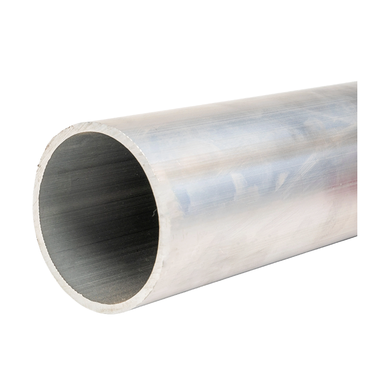


Reinforcing Steel Aluminum Strand: Structure, Performance, Manufacturing Quality, and Power-System Applications
Content
- 1 1. Product Overview
- 2 2. Standardized Product Range
- 3 3. Why the Aluminum and Steel Combination Matters
- 4 4. Main Advantages Compared with Conventional Conductors
- 5 5. Manufacturing Process and Quality Control
- 6 6. Advanced Manufacturing Strengths of the Supplier
- 7 7. Electrical Performance
- 8 8. Mechanical Performance and Environmental Reliability
- 9 9. Applications in Power Systems
- 10 10. Installation Recommendations
- 11 11. Product Advantages for Engineering Procurement
- 12 12. Recommended Selection Process
- 13 13. Quality, Safety, and Compliance Considerations
- 14 14. Frequently Asked Questions
- 14.1 Q1: What is reinforcing steel aluminum strand?
- 14.2 Q2: What is the main advantage over an all-aluminum conductor?
- 14.3 Q3: Does the steel core reduce conductivity?
- 14.4 Q4: What nominal sizes are available?
- 14.5 Q5: Can the product be used for long spans?
- 14.6 Q6: Is it suitable for coastal environments?
- 14.7 Q7: What installation equipment is required?
- 14.8 Q8: How should connectors be selected?
- 14.9 Q9: What quality documents should be requested?
- 14.10 Q10: Can the manufacturer provide customized solutions?
- 14.11 Q11: What is the usual delivery length?
- 14.12 Q12: How does the product support busbar and power-equipment projects?
- 15 15. Conclusion
- 16 References
- 17 Product: Reinforcing Steel Aluminum Strand
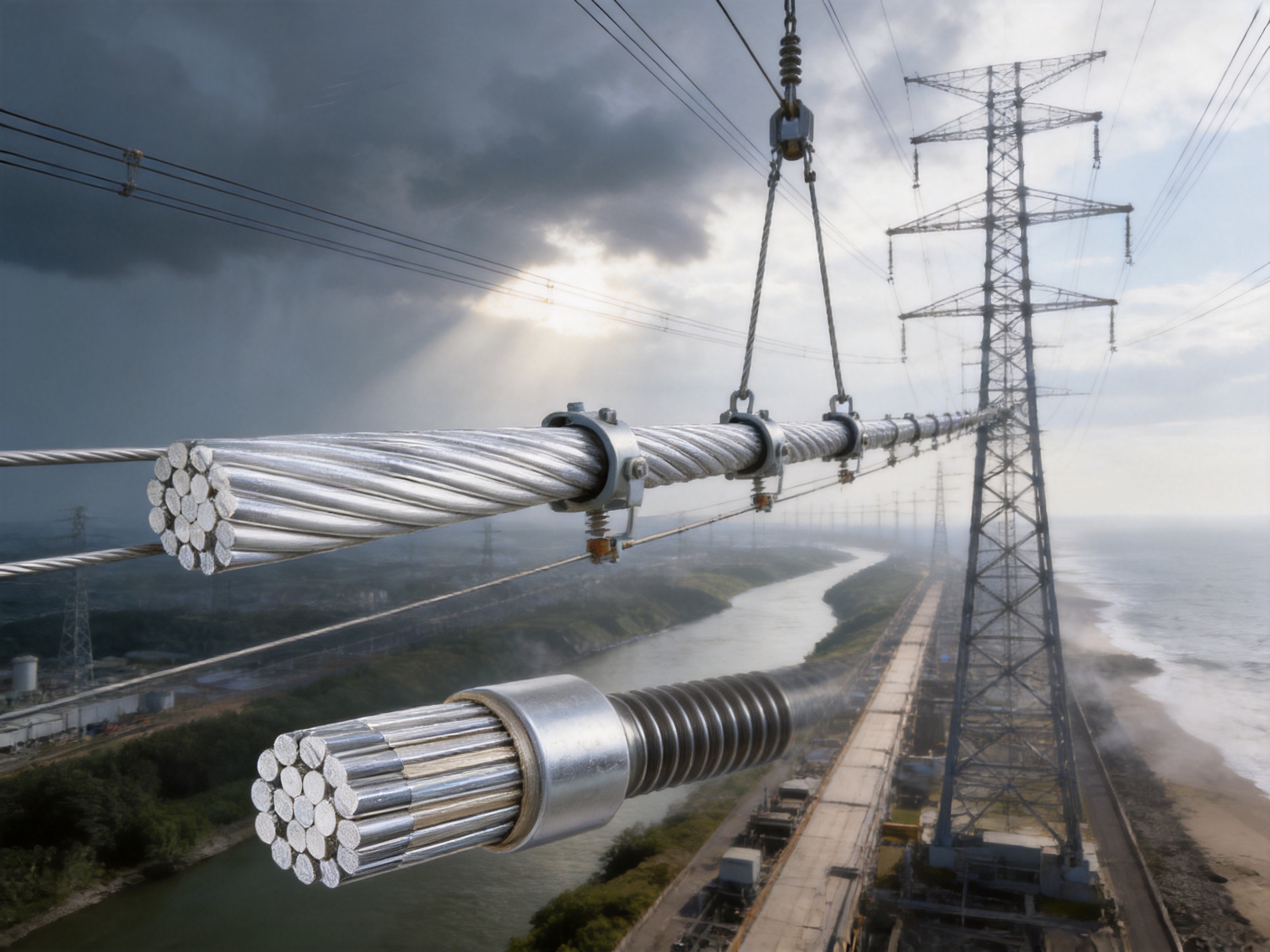
Reinforcing steel aluminum strand is a composite conductor designed to combine the electrical conductivity of aluminum with the mechanical strength of a steel core. This combination makes it suitable for overhead transmission, high-tension distribution, grounding and shielding applications, and specialized hardware connections such as damping-type end caps. By integrating two complementary materials into one stranded conductor, the product provides a practical balance between current-carrying capacity, tensile strength, weight, installation performance, and environmental resistance.
In modern power infrastructure, conductors must withstand more than electrical loading. They are exposed to wind, ice, vibration, temperature changes, pollution, ultraviolet radiation, salt spray, and long-term mechanical tension. A conductor that performs well electrically but lacks mechanical stability may experience excessive sag or premature failure. Conversely, a mechanically strong conductor with insufficient conductivity can increase power losses and reduce system efficiency. Reinforcing steel aluminum strand addresses these challenges through a layered construction in which aluminum strands carry most of the electrical current and a steel core provides structural reinforcement.
Manufactured according to the GB1179-83 standard, the product is available in a broad range of nominal cross-sections from 10/2 mm² to 240/30 mm². Depending on the specification, six to thirty aluminum strands are wrapped around one to seven steel-core strands. This flexible construction allows engineers to select a suitable conductor for different span lengths, current requirements, mechanical loads, and installation conditions.
1. Product Overview
Reinforcing steel aluminum strand is a stranded composite conductor consisting of an inner steel core and one or more outer layers of aluminum wires. The steel core is responsible primarily for tensile strength and mechanical stability. The aluminum outer layers provide the main conductive path and protect the internal steel from direct exposure to the atmosphere.
The product is commonly associated with aluminum conductor steel reinforced construction, in which the proportion of aluminum and steel is selected according to the required electrical and mechanical performance. A greater aluminum area generally improves current-carrying capability, while a suitable steel-core configuration improves strength, span capability, and resistance to sag.
The strand is not a simple combination of loose wires. Its performance depends on accurate wire drawing, controlled stranding pitch, stable pre-twisting, dimensional consistency, and reliable surface quality. The relationship between the aluminum layers and the steel core must remain stable during installation and operation. If the strands loosen, shift, or experience uneven tension, the conductor may develop local stress concentrations, increased resistance, or premature fatigue.
For this reason, a professional manufacturing process must control the properties of the raw materials, the diameter of individual wires, the lay direction, the stranding pitch, the tension applied during stranding, the compactness of the finished conductor, and the final inspection results. These factors determine whether the product can maintain reliable performance throughout its service life.
2. Standardized Product Range
The product range covers nominal cross-sections from 10/2 mm² to 240/30 mm². In this designation, the first number generally represents the approximate aluminum area, while the second number represents the approximate steel-core area. This format gives engineers a quick indication of the relative electrical and mechanical composition of the conductor.
The strand structure may contain six to thirty aluminum wires and one to seven steel-core wires. Smaller constructions are suitable for applications requiring moderate current capacity and lower overall dimensions. Larger constructions are intended for higher loads, longer spans, and demanding mechanical conditions.
Typical technical parameters include calculated total cross-sectional areas from approximately 12.37 mm² to 275.96 mm² and outer diameters from approximately 4.50 mm to 21.60 mm. Depending on the selected size, the direct-current resistance may range from no more than approximately 2.706 Ω/km to 0.1410 Ω/km. Calculated tensile strength ranges from approximately 4,012 N to 91,120 N, while calculated weight ranges from approximately 42.9 kg/km to 964.2 kg/km.
These values are used during electrical design, mechanical calculation, structure selection, transportation planning, and installation preparation. Because the actual performance depends on the selected construction and production tolerances, project engineers should confirm the final technical data against the approved product specification before ordering or installation.
| Parameter | Typical Product Range | Engineering Significance |
| Nominal cross-section | 10/2 mm² to 240/30 mm² | Supports different current and mechanical requirements |
| Aluminum wire quantity | 6 to 30 wires | Influences conductivity, diameter, and flexibility |
| Steel-core wire quantity | 1 to 7 wires | Influences tensile strength and structural stability |
| Calculated cross-sectional area | 12.37 mm² to 275.96 mm² | Used for electrical and mechanical calculations |
| Outer diameter | 4.50 mm to 21.60 mm | Important for fittings, clearances, and installation tools |
| Calculated tensile strength | 4,012 N to 91,120 N | Determines mechanical load capability |
| Calculated weight | 42.9 kg/km to 964.2 kg/km | Supports sag, tension, transport, and support design |
| General delivery length | Normally less than 2,000 m | Facilitates handling, transportation, and project planning |
3. Why the Aluminum and Steel Combination Matters
Aluminum is widely used in electrical conductors because it has good conductivity, low density, and strong resistance to atmospheric corrosion. It is lighter than copper and can provide a favorable current-carrying capacity at a lower material weight. However, aluminum alone is not always sufficient for long spans or high mechanical loads. Its tensile strength and elastic behavior may limit span length, increase sag, or require additional structural support.
Steel provides the opposite set of characteristics. It has high tensile strength and good mechanical rigidity, but its electrical conductivity is much lower than that of aluminum. By positioning the steel inside the conductor and placing aluminum around it, the design uses each material where it is most effective.
The aluminum strands carry most of the operating current and form the external surface. The steel core supports the conductor during stringing and operation, helps limit sag, and improves resistance to wind and ice loading. This arrangement is especially useful where the distance between support structures is significant or where environmental conditions create high mechanical stress.
Compared with a standard all-aluminum conductor, reinforcing steel aluminum strand normally provides greater tensile strength and longer span capability. Compared with a conductor made primarily of steel, it offers much better conductivity and lower electrical losses. The practical advantage is not that it maximizes one individual property, but that it provides a balanced performance profile for demanding power-system applications.
4. Main Advantages Compared with Conventional Conductors
4.1 Higher Mechanical Strength
The principal advantage of the steel core is improved tensile strength. During installation, conductors may be subjected to substantial pulling tension. During operation, they must support their own weight and resist wind, ice, vibration, and thermal expansion. The steel core allows the conductor to tolerate higher mechanical loads than many all-aluminum alternatives.
Higher strength can also reduce sag over long spans. Lower sag helps maintain the required clearance from the ground, buildings, roads, railway systems, and other conductors. In suitable projects, longer spans may reduce the number of towers, poles, or support structures required. This can lower civil-construction costs and simplify route planning.
4.2 Effective Electrical Performance
Although steel contributes less to electrical conductivity, the outer aluminum layers provide a substantial conductive area. The product is therefore capable of carrying power efficiently while maintaining the mechanical benefits of the steel core. The specified direct-current resistance values support conductor selection and voltage-drop calculations.
The material information identifies electrical-grade aluminum with a purity of at least 99.7 percent. With controlled annealing, the aluminum conductivity is stated to exceed 61 percent IACS under the applicable material conditions. Actual conductor performance depends on the final construction, temperature, contact conditions, and test method, but the use of high-purity aluminum provides a strong basis for consistent electrical properties.
4.3 Favorable Strength-to-Weight Ratio
Aluminum is significantly lighter than copper, while steel contributes high tensile strength relative to its mass. The combined structure can therefore provide a useful strength-to-weight ratio for overhead applications. Lower conductor weight can reduce the load transferred to towers, crossarms, insulators, and foundations.
This advantage becomes increasingly important when a project requires long spans, difficult terrain crossings, river crossings, industrial corridors, or transmission routes through areas where support structures are expensive to construct. The final selection must still account for conductor weight, ice loading, wind pressure, thermal rating, and local design standards.
4.4 Environmental Resistance
The aluminum outer surface provides good resistance to ordinary atmospheric exposure. It is also more resistant to many corrosive environments than unprotected steel. The steel core is generally protected by the surrounding aluminum and, where applicable, by galvanizing or another controlled surface treatment.
The supplied technical information identifies a galvanized steel core with a zinc coating weight of at least 300 g/m². A properly controlled zinc coating helps reduce corrosion risk during storage, installation, and service. In coastal or industrial areas, however, the conductor should still be selected and maintained according to the severity of the local environment.
4.5 Stable Performance During Temperature Changes
Overhead conductors experience changes in operating temperature because of current loading, solar radiation, ambient temperature, and wind. These changes affect conductor length, tension, and sag. A composite aluminum-steel structure is designed to manage the interaction between the two materials and maintain predictable mechanical behavior.
The product information states that the coefficient of thermal expansion remains stable within a temperature range of approximately -40°C to +80°C. This characteristic supports design calculations for areas exposed to broad seasonal temperature changes. Engineers should use the approved thermal and mechanical data for the specific conductor size when calculating final sag and tension.
5. Manufacturing Process and Quality Control
The performance of a reinforcing steel aluminum strand depends heavily on manufacturing precision. A conductor can meet its nominal size while still failing to deliver reliable service if its strand tension, pitch, surface condition, or material quality is inconsistent. Jiangsu Wopeng Power Technology Co., Ltd. emphasizes process control, modern equipment, and standardized inspection as part of its production approach.
5.1 Raw Material Selection
Production begins with the selection and verification of aluminum wire rod, steel wire, and protective coating materials. Electrical-grade aluminum must meet the required purity, conductivity, chemical composition, and mechanical properties. Steel wires must provide the required tensile strength, dimensional accuracy, surface condition, and coating quality.
Incoming materials should be checked against purchase specifications and applicable standards. Typical checks may include diameter measurement, tensile testing, elongation testing, electrical resistivity testing, surface inspection, and coating verification. Material identification and batch traceability help link the finished conductor to its source materials.
5.2 Aluminum Wire Drawing and Annealing
Aluminum wire drawing reduces the raw material to the required single-wire diameter while improving dimensional accuracy. The drawing process must be carefully controlled because excessive deformation can affect conductivity, ductility, and surface quality.
After drawing, controlled annealing can restore appropriate softness and improve conductivity. The objective is to achieve a stable combination of electrical performance and flexibility without creating excessive variation between individual wires. Temperature, time, cooling conditions, and furnace uniformity all influence the result.
Precise wire dimensions are essential because the aluminum strands must fit together evenly during stranding. A variation in diameter can create local gaps, uneven pressure, or an inconsistent outer surface. These defects may affect the final diameter, flexibility, electrical resistance, and interaction with fittings.
5.3 Steel-Core Preparation
The steel core is prepared through wire drawing, heat treatment where required, and surface protection. Galvanizing provides a zinc coating intended to protect the steel from corrosion. Coating uniformity is important because exposed or thin areas can become vulnerable during storage and service.
The steel wires are checked for diameter, tensile strength, elongation, coating mass, adhesion, and surface defects. The core must remain dimensionally stable during stranding so that the aluminum layers can be applied with consistent tension.
5.4 Controlled Stranding
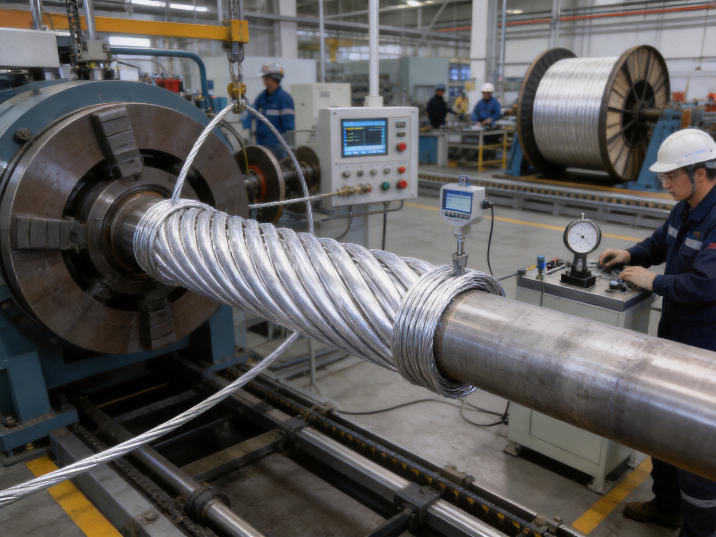
Stranding is the central assembly operation. Aluminum wires are wrapped around the steel core in one or more layers according to the approved design. The stranding machine must maintain the specified lay direction, pitch, wire tension, and alignment.
A scientifically selected pitch ratio distributes mechanical stress across the conductor and helps prevent excessive movement between wires. If the pitch is too short, the conductor may become unnecessarily rigid and difficult to handle. If it is too long, the strands may be more likely to shift or loosen. The correct ratio provides a balance between flexibility, compactness, stability, and mechanical performance.
Pre-twisting and controlled back-tension help keep the strand stable after it leaves the machine. The supplied product information describes a process intended to prevent strand loosening and maintain reliable geometry during long-term loading. Consistent tension between layers is particularly important because uneven loading can cause certain wires to carry more mechanical stress than others.
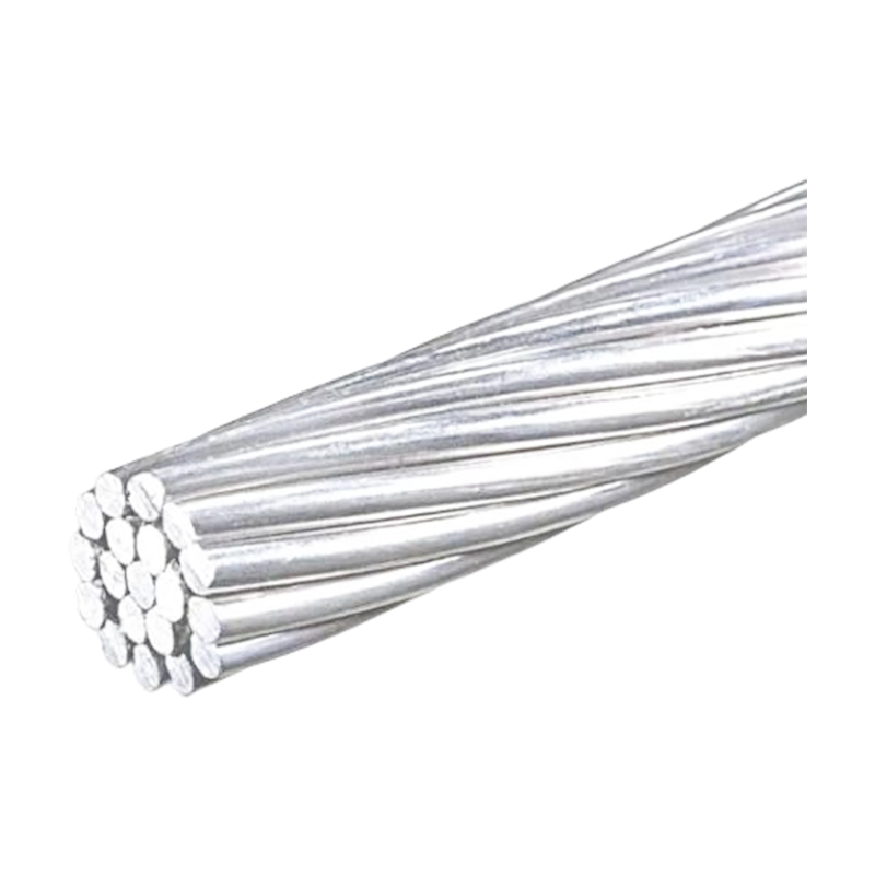
Reinforcing Steel Aluminum Strand
5.5 Surface and Dimensional Inspection
After stranding, the finished conductor is inspected for outer diameter, roundness, surface condition, wire displacement, broken strands, scratches, corrosion, and visible defects. Dimensional measurements are compared with the approved specification.
Surface quality is important for both electrical and mechanical reasons. Deep scratches may reduce the effective cross-section of an aluminum wire or create stress-concentration points. Protruding wires may interfere with compression fittings and handling equipment. Local deformation may indicate improper machine settings or excessive tension during production.
Modern manufacturing lines can use digital measurement instruments, calibrated diameter gauges, optical systems, and process-monitoring equipment. The purpose of these systems is to identify deviations early rather than relying only on final inspection.
5.6 Routine Testing and Documentation
Routine tests may include direct-current resistance measurement, tensile testing, dimensional verification, wire-count confirmation, surface inspection, and coating checks. Depending on the project and applicable standard, additional tests may be performed for elongation, wrapping, heat exposure, corrosion resistance, or fatigue behavior.
Testing collaboration with independent third-party institutions can provide additional validation for selected products or project orders. A complete quality record should include material certificates, production-batch identification, inspection results, test dates, equipment calibration information, and packaging records.
Jiangsu Wopeng Power Technology Co., Ltd. reports the use of modern production lines, vacuum casting systems, CNC machining equipment, automated assembly technologies, and standardized inspection procedures across its broader power-equipment product portfolio. While the manufacturing route for a stranded conductor differs from that of an epoxy-cast busbar, the same quality-management principles are valuable: controlled materials, repeatable processes, calibrated equipment, and documented inspection.
6. Advanced Manufacturing Strengths of the Supplier
A reliable supplier must provide more than a catalog size. It should be capable of understanding the application, confirming the required conductor construction, coordinating production, supporting inspection, and maintaining consistency from one order to the next.
Jiangsu Wopeng Power Technology Co., Ltd. was founded in 2018 and focuses on high- and low-voltage busbar systems and related power-transmission equipment. Its product portfolio includes epoxy resin vacuum-cast tube busbars, low-voltage cast-resin busways, copper and aluminum tube busbars, wind-power tube busbars, compact busbar systems, and sliding contact line systems.
This broader product background is relevant because conductor and busbar projects often require coordination between electrical design, mechanical support, insulation, connection hardware, and installation conditions. A manufacturer with experience in power-transmission equipment can offer a more complete understanding of system requirements than a supplier focused only on raw wire production.
The company operates modern production facilities supported by engineers, technical specialists, and production personnel. Its stated quality procedures include high-voltage testing, insulation testing, mechanical verification, routine inspection, and collaboration with external testing organizations. For customers purchasing reinforcing steel aluminum strand for a larger electrical project, these capabilities can support technical communication and project-specific documentation.
The company also reports that its products are used in more than seventeen provinces and in sectors such as power generation, substations, wind energy, industrial manufacturing, rail transit, and large commercial facilities. Experience across different operating environments can help a supplier identify practical concerns involving temperature, vibration, current, installation space, environmental exposure, and maintenance access.
Another important strength is the ability to provide customized or OEM solutions. Projects may differ in conductor size, delivery length, packaging method, test requirements, labeling, documentation, and connection accessories. A manufacturer capable of adapting its production and inspection procedures can reduce the risk of specification gaps between the design office, procurement team, installer, and final operator.
7. Electrical Performance
The electrical performance of reinforcing steel aluminum strand is determined by the aluminum cross-sectional area, aluminum resistivity, strand construction, operating temperature, and connection quality. Direct-current resistance is one of the main values used in system design. Lower resistance generally means lower I²R losses at a given current.
The product information provides resistance values ranging from approximately 2.706 Ω/km for smaller constructions to approximately 0.1410 Ω/km for larger constructions. These values should be understood as size-dependent figures rather than a single performance value for the entire product family.
At high frequency, current distribution may be influenced by skin effect and the geometry of the stranded conductor. The provided technical information identifies a measured skin-effect coefficient below 1.05 under high-frequency conditions and states that the increase in AC resistance is controlled within 8 percent. Such figures may be relevant in specialized applications, but the final design should use test data corresponding to the actual conductor construction and operating frequency.
The product information also identifies a short-circuit thermal capacity of 150 kA²·s and states that conductivity degradation after one hundred thermal cycles does not exceed 2 percent. These figures indicate an emphasis on thermal stability and repeated temperature exposure. For a specific project, short-circuit calculations must consider fault duration, conductor size, initial temperature, final allowable temperature, connection points, and applicable design standards.
8. Mechanical Performance and Environmental Reliability
Mechanical reliability is central to the value of a reinforced conductor. The steel core must maintain its strength under installation tension and long-term loading. The aluminum strands must remain properly positioned and must not experience unacceptable deformation or fatigue.
The product data identifies calculated tensile strengths from approximately 4,012 N to 91,120 N, depending on the size and construction. The actual allowable working tension is lower than the ultimate tensile strength and must be established according to engineering calculations and applicable standards.
The supplied information states that creep deformation is limited to within 0.05 percent under long-term operating loads. It also references a two-million-cycle wind-induced vibration fatigue test. Aeolian vibration, galloping, and sub-conductor movement can be significant in overhead systems, particularly in open terrain or areas with frequent wind. Appropriate dampers, clamps, spacers, and fittings remain important even when the conductor itself has good fatigue resistance.
Environmental validation is also described for temperatures from -40°C to +80°C, an ice coating load of 30 mm, five thousand hours of salt-spray testing, and five thousand hours of ultraviolet aging. The reported results include retention of more than 95 percent of tensile strength after salt-spray exposure and no significant surface degradation after UV aging.
These results provide useful indicators of durability, but project conditions should always be reviewed individually. Coastal environments, chemical plants, heavy industrial pollution, desert dust, and areas with severe icing may require additional protective measures, inspection intervals, or alternative construction choices.
9. Applications in Power Systems
9.1 Overhead Transmission Lines
Overhead transmission is the most recognized application. A conductor must carry electrical power while spanning the distance between towers. The steel core improves mechanical strength and can enable longer spans than an equivalent all-aluminum conductor.
Longer spans may be useful when crossing rivers, highways, railways, valleys, industrial zones, or environmentally sensitive areas. Fewer support structures can reduce foundation work, land use, visual impact, and maintenance requirements. The designer must still evaluate sag, wind pressure, ice loading, clearance, tower loading, and thermal rating.
9.2 High-Tension Distribution
In high-tension distribution systems, the conductor must remain mechanically stable under changing weather and load conditions. Sagging can reduce clearance and increase the risk of contact with vegetation, buildings, vehicles, or adjacent lines.
The reinforcing steel aluminum structure helps maintain line geometry and supports stable operation. Its relatively favorable weight and strength characteristics can be useful in rural networks, industrial supply systems, and regional distribution corridors.
9.3 Ground Wires and Shield Wires
At the top of transmission towers, reinforced strands may be used as ground wires or shield wires. Their role is to intercept lightning and provide a low-impedance path toward the grounding system. Mechanical strength is particularly important because the shield wire must remain securely supported and properly positioned above the phase conductors.
The suitability of a particular conductor for lightning protection depends on the required fault-current capacity, mechanical loading, tower geometry, grounding resistance, and coordination with the overall protection design.
9.4 Damping and Hardware Connections
The product is also described as a damping wire for hardware connection applications, including damping-type end caps. In these applications, conductor compatibility, flexibility, connection strength, and resistance stability are important.
Compression connectors and transition fittings must be selected for aluminum-to-steel conductor construction. Incorrect fittings can create high contact resistance, local heating, oxidation, strand damage, or mechanical slippage. Installation tools must be calibrated, and the connector manufacturer’s compression sequence must be followed precisely.
9.5 Renewable-Energy and Industrial Infrastructure
Wind farms, photovoltaic facilities, substations, and industrial plants often require reliable conductors across large sites or between generating equipment and collection systems. While the final conductor choice depends on voltage level and system architecture, reinforced aluminum strands may be useful where mechanical loading, outdoor exposure, and long-distance routing are important.
The supplier’s broader experience with wind-power tube busbars, substations, industrial manufacturing, and other power equipment can support integrated project discussions. Customers may benefit from coordinating conductor requirements with busbar systems, support structures, connection hardware, and protection equipment.
10. Installation Recommendations
Proper installation is essential. Even a high-quality conductor can be damaged by excessive pulling tension, improper bending, unsuitable sheaves, incorrect clamps, or poorly installed connectors.
10.1 Tension Stringing
Tension stringing is often used to control conductor clearance during installation. The pulling tension must remain within the approved limits. Exceeding the elastic limit of the conductor or applying sudden shock loads may create permanent deformation or damage individual aluminum strands.
Stringing blocks should have a suitable diameter and groove profile. The conductor should not be dragged over rough ground, sharp edges, contaminated surfaces, or objects that can damage the aluminum wires. During pulling, the crew should monitor tension, speed, sag, and possible contact with structures.
10.2 Bending and Handling
Although the strand has useful flexibility, it should not be bent more sharply than permitted by the product specification. Kinks, flattened sections, birdcaging, and localized strand displacement should be avoided. Reels must be stored on stable ground and protected from impact, standing water, corrosive chemicals, and uncontrolled rolling.
10.3 Connector Compatibility
Connectors must be designed for the specific aluminum-steel construction. Compression fittings should match the conductor diameter, strand arrangement, and material combination. The contact surfaces must be clean and prepared according to the connector manufacturer’s instructions.
Transition connections require special attention because aluminum and steel have different electrical and mechanical properties. The connection must provide stable current transfer while maintaining tensile strength. After installation, the connection should be inspected for correct compression, alignment, surface condition, and signs of overheating.
10.4 Inspection and Maintenance
Routine inspection should examine conductor surface condition, sag, vibration dampers, clamps, end fittings, support points, and areas exposed to pollution or salt. Thermal imaging may help identify abnormal heating at connections. Visual inspection can identify corrosion, broken wires, strand displacement, birdcaging, or mechanical damage.
Inspection intervals should reflect the operating environment. Coastal regions, areas with severe wind, regions with heavy icing, and industrial zones with corrosive pollutants may require more frequent checks than moderate inland environments.
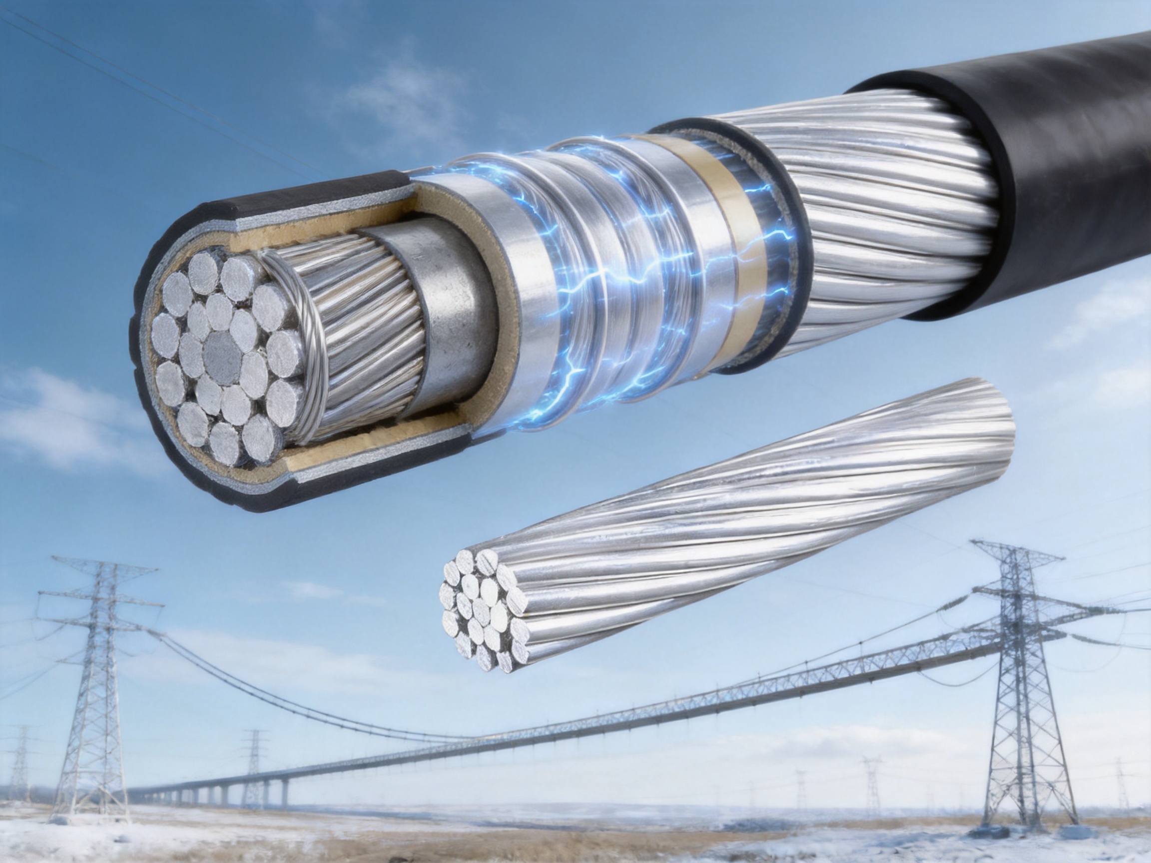
11. Product Advantages for Engineering Procurement
From a procurement perspective, a strong product is one that can be clearly specified, consistently manufactured, properly tested, and delivered with complete documentation. The broad range from 10/2 mm² to 240/30 mm² gives engineers several options without requiring a completely different supplier for each application.
Standardized construction simplifies comparison between suppliers. Engineers can evaluate cross-sectional area, aluminum and steel proportions, diameter, resistance, tensile strength, weight, and delivery length using a common technical framework. Standardization also supports replacement planning and future maintenance.
Another advantage is the balance between catalog production and customization. Standard products provide predictable lead times and established production procedures, while customized solutions allow the manufacturer to address special packaging, inspection, labeling, length, or project documentation requirements.
The product’s combination of electrical and mechanical performance can also reduce total project cost. A conductor with greater tensile strength may permit longer spans or reduce the need for additional supports. A conductor with stable resistance and reliable connections can reduce operating losses and maintenance risks. These benefits should be assessed over the entire project life cycle rather than by initial purchase price alone.
12. Recommended Selection Process
Selection should begin with the system’s electrical requirements. Engineers should establish the continuous current, emergency loading, short-circuit duty, operating voltage, expected temperature, and allowable losses. The required aluminum area and resistance can then be evaluated.
The next step is mechanical analysis. Span length, support spacing, wind pressure, ice loading, installation tension, allowable sag, tower strength, and vibration conditions must be considered. The steel-core arrangement should be selected to provide sufficient mechanical capacity without adding unnecessary weight or cost.
Environmental factors should then be reviewed. These may include temperature range, coastal salt, industrial pollution, ultraviolet exposure, rainfall, icing, altitude, and chemical contamination. The conductor’s surface protection and maintenance requirements should match the actual site.
Finally, connection and installation requirements must be confirmed. The selected conductor should be compatible with suspension clamps, tension clamps, dead-end fittings, compression sleeves, dampers, grounding accessories, and testing instruments. A supplier should provide dimensional information and installation recommendations before final approval.
| Selection Factor | Questions to Confirm | Relevant Product Information |
| Electrical loading | What continuous and emergency current must be carried? | Aluminum area, DC resistance, thermal capability |
| Mechanical loading | What span, wind, ice, and tension conditions apply? | Steel-core area, tensile strength, weight |
| Installation | Which pulling equipment and fittings will be used? | Outer diameter, flexibility, connector compatibility |
| Environment | Will the conductor face salt, pollution, UV, or extreme temperature? | Aluminum surface, galvanized core, environmental test data |
| Quality documentation | What inspection and certification records are required? | Routine test reports, material records, traceability |
| Logistics | What reel size, delivery length, and packaging are practical? | General delivery length below 2,000 m, project-specific packing |
13. Quality, Safety, and Compliance Considerations
Compliance with GB1179-83 provides a defined basis for product construction and technical parameters. However, projects may also require additional national, regional, or international standards depending on the installation location and system type.
Customers should verify the required standards during the design and procurement stage. The technical agreement should identify conductor designation, wire arrangement, nominal dimensions, resistance, tensile strength, surface requirements, packaging, marking, testing, and acceptance criteria.
Safety begins with correct design and continues through transportation, installation, commissioning, and maintenance. Conductors must be handled as energized-system components even before commissioning because nearby circuits may remain live. Installation personnel must follow approved grounding, clearance, lifting, tensioning, and personal-protection procedures.
Quality records should be retained throughout the project. Batch numbers, reel numbers, inspection reports, test certificates, installation records, and field observations can help resolve future questions and support maintenance planning.
14. Frequently Asked Questions
Q1: What is reinforcing steel aluminum strand?
It is a composite stranded conductor made by wrapping aluminum wires around a steel-core assembly. The aluminum carries most of the electrical current, while the steel core provides mechanical strength, support, and improved resistance to sag.
Q2: What is the main advantage over an all-aluminum conductor?
The main advantage is higher tensile strength and improved span capability. The steel core allows the conductor to withstand greater mechanical loading and maintain better clearance under wind, ice, and long-span conditions.
Q3: Does the steel core reduce conductivity?
The steel core contributes less to conductivity than aluminum, but the outer aluminum layers provide the primary conductive area. The final resistance depends on the conductor size, aluminum area, construction, and operating temperature. The product range includes multiple sizes so engineers can select suitable electrical performance.
Q4: What nominal sizes are available?
The stated nominal range is from 10/2 mm² to 240/30 mm². The correct size depends on electrical loading, span length, mechanical conditions, allowable sag, and applicable standards.
Q5: Can the product be used for long spans?
Yes. The steel reinforcement makes it suitable for many long-span applications, including overhead transmission and distribution crossings. Final suitability must be confirmed through sag-tension calculations and structural analysis.
Q6: Is it suitable for coastal environments?
It can be used in coastal environments when the conductor construction, protective coating, fittings, and maintenance plan are appropriate. The aluminum exterior provides useful atmospheric corrosion resistance, while the galvanized steel core helps protect the internal steel. Severe salt exposure may require enhanced inspection and project-specific corrosion evaluation.
Q7: What installation equipment is required?
Typical projects may require tension-stringing equipment, suitable stringing blocks, calibrated compression tools, compatible clamps and connectors, conductor reels, lifting equipment, and inspection instruments. The equipment should be selected according to the conductor diameter, weight, tension, and installation method.
Q8: How should connectors be selected?
Connectors must be designed for the specific aluminum-steel conductor construction. Aluminum-to-steel transition fittings or compression connectors should be selected according to the conductor designation and the connector manufacturer’s instructions. Using an unsuitable connector can cause heating, slippage, oxidation, or mechanical failure.
Q9: What quality documents should be requested?
Customers may request material certificates, conductor dimensional records, direct-current resistance results, tensile test results, coating verification, inspection reports, batch traceability, packing records, and applicable conformity certificates. Project-specific testing should be agreed before production.
Q10: Can the manufacturer provide customized solutions?
Customized solutions may be available for conductor size, delivery length, packaging, labeling, inspection, and project documentation. Customers should provide the required standard, application conditions, technical parameters, and delivery schedule during the inquiry stage.
Q11: What is the usual delivery length?
The general delivery length is normally less than 2,000 meters, although the practical length depends on conductor size, reel capacity, transportation requirements, and project specifications.
Q12: How does the product support busbar and power-equipment projects?
Reinforcing steel aluminum strand is primarily a stranded conductor, while tubular busbars are rigid power-transmission components. They may serve different functions, but both require accurate electrical design, mechanical reliability, controlled manufacturing, compatible connections, and documented inspection. A supplier experienced in both conductor-related products and busbar systems can support broader power-infrastructure projects.
15. Conclusion
Reinforcing steel aluminum strand is a practical solution for power systems that require both electrical conductivity and mechanical strength. Its aluminum outer layers provide an efficient current path, while its steel core supports long spans, improves resistance to sag, and helps the conductor withstand wind, ice, vibration, and installation tension.
The product range from 10/2 mm² to 240/30 mm² provides flexibility for different engineering requirements. Standardized dimensions, resistance values, tensile strength, calculated weight, and delivery lengths make the conductor easier to specify and compare. The combination of high-purity aluminum, protected steel, controlled stranding, stable pitch ratios, and inspection procedures supports reliable performance.
Jiangsu Wopeng Power Technology Co., Ltd. adds value through its broader experience in high- and low-voltage busbar systems, power-transmission equipment, automated production, technical engineering, and quality control. Its manufacturing capabilities, inspection procedures, product range, and project experience provide a foundation for supplying conductors and related power-equipment solutions to demanding industrial applications.
For successful project results, the conductor should be selected through a complete electrical, mechanical, environmental, installation, and maintenance review. When the design data, manufacturing controls, compatible fittings, and field procedures are properly coordinated, reinforcing steel aluminum strand can provide dependable service in overhead transmission, distribution, grounding, shielding, damping, renewable-energy, and industrial power applications.
References
1. GB1179-83, Round Wire Concentric Lay Overhead Electrical Stranded Conductors.
2. IEC 61089, Round Wire Concentric Lay Overhead Electrical Stranded Conductors.
3. ASTM B399, Concentric-Lay-Stranded Aluminum-Alloy 6201-T81 Conductors.
4. International Annealed Copper Standard, Electrical Conductivity Reference Values.
5. General engineering practices for overhead line sag-tension calculation and conductor installation.
6. Manufacturer technical data for reinforcing steel aluminum strand, including dimensional, electrical, mechanical, and environmental performance information.
7. Manufacturer quality-management and inspection procedures for power-transmission and busbar systems.
8. Engineering guidance for compression connectors, grounding wires, shield wires, vibration control, and overhead conductor maintenance.
For product selection, technical confirmation, OEM requirements, and project consultation, customers should provide the required conductor designation, application, operating environment, testing requirements, delivery length, and installation conditions so that the appropriate specification and documentation can be prepared.
Product: Reinforcing Steel Aluminum Strand




-
 +86-180 3625 3000
-
 admin@wpbusbar.com
-
 No. 8, Yanjin Road, Chengxi Industrial Park, Shanyang Town, Baoying County, Yangzhou City, Jiangsu Province, China
Copyright © Jiangsu Wopeng Power Technology Co., Ltd.
All Rights Reserved.
 Custom Insulated Bus Bar Manufacturer
Tubular Busbar System Factory
Custom Insulated Bus Bar Manufacturer
Tubular Busbar System Factory