

 EN
EN

 English
 русский
 Français
 Español
 عربى
عربى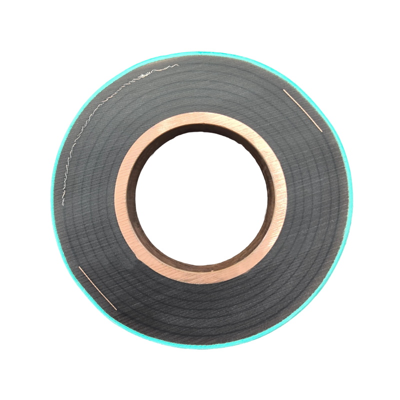
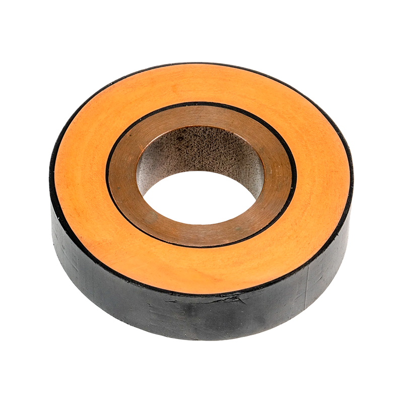
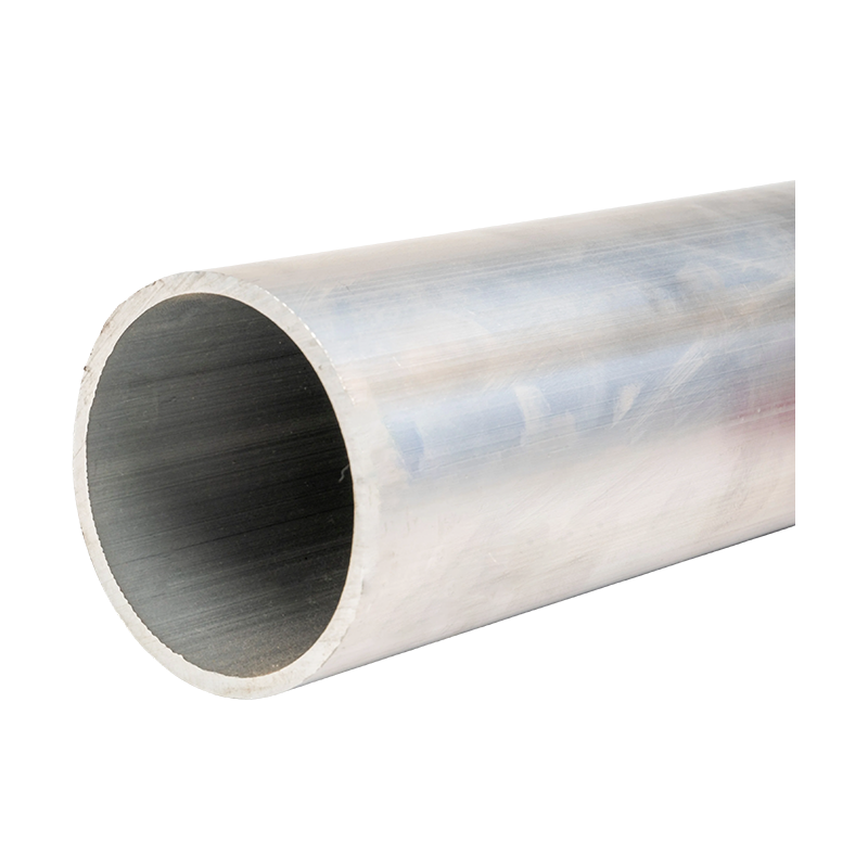
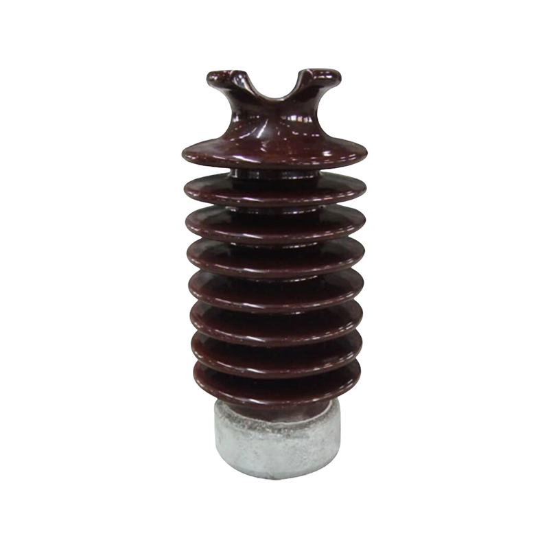

PTFE Tubular Bus Bar: Extreme-Environment Insulation, Manufacturing Excellence, and Application Guide
Content
- 1 1. What Is a PTFE Tubular Bus Bar?
- 2 2. Why PTFE Is Suitable for Severe Electrical Environments
- 3 3. Main Technical Advantages
- 4 4. Comparison with Other Insulated Busbar Technologies
- 5 5. Manufacturing Process and Quality Control
- 6 6. Testing and Inspection
- 7 7. Application Solutions
- 8 8. Advantages of Working with an Experienced Manufacturer
- 9 9. Design Considerations Before Ordering
- 10 10. Installation and Maintenance Recommendations
- 11 11. Cost, Lifecycle Value, and Sustainability
- 12 12. Technical Challenges and How They Are Managed
- 13 13. Recommended Industries and Use Cases
- 14 14. Frequently Asked Questions
- 14.1 Q1: What is the main advantage of PTFE tubular bus bar?
- 14.2 Q2: What conductor materials can be used?
- 14.3 Q3: What temperature range can the product withstand?
- 14.4 Q4: Is PTFE tubular bus bar suitable for outdoor applications?
- 14.5 Q5: Can the product achieve IP68 protection?
- 14.6 Q6: How are electric fields controlled?
- 14.7 Q7: Can PTFE tubular bus bar be customized?
- 14.8 Q8: Is PTFE tubular bus bar more expensive than epoxy resin busbar?
- 14.9 Q9: How long can PTFE tubular bus bar operate?
- 14.10 Q10: What information is required for a quotation?
- 14.11 Q11: Can the busbar be installed in a cable trench?
- 14.12 Q12: Is monitoring available?
- 15 15. Why Choose Jiangsu Wopeng Power Technology
- 16 16. Conclusion
- 17 References
- 18 Product: PTFE Tubular Bus Bar
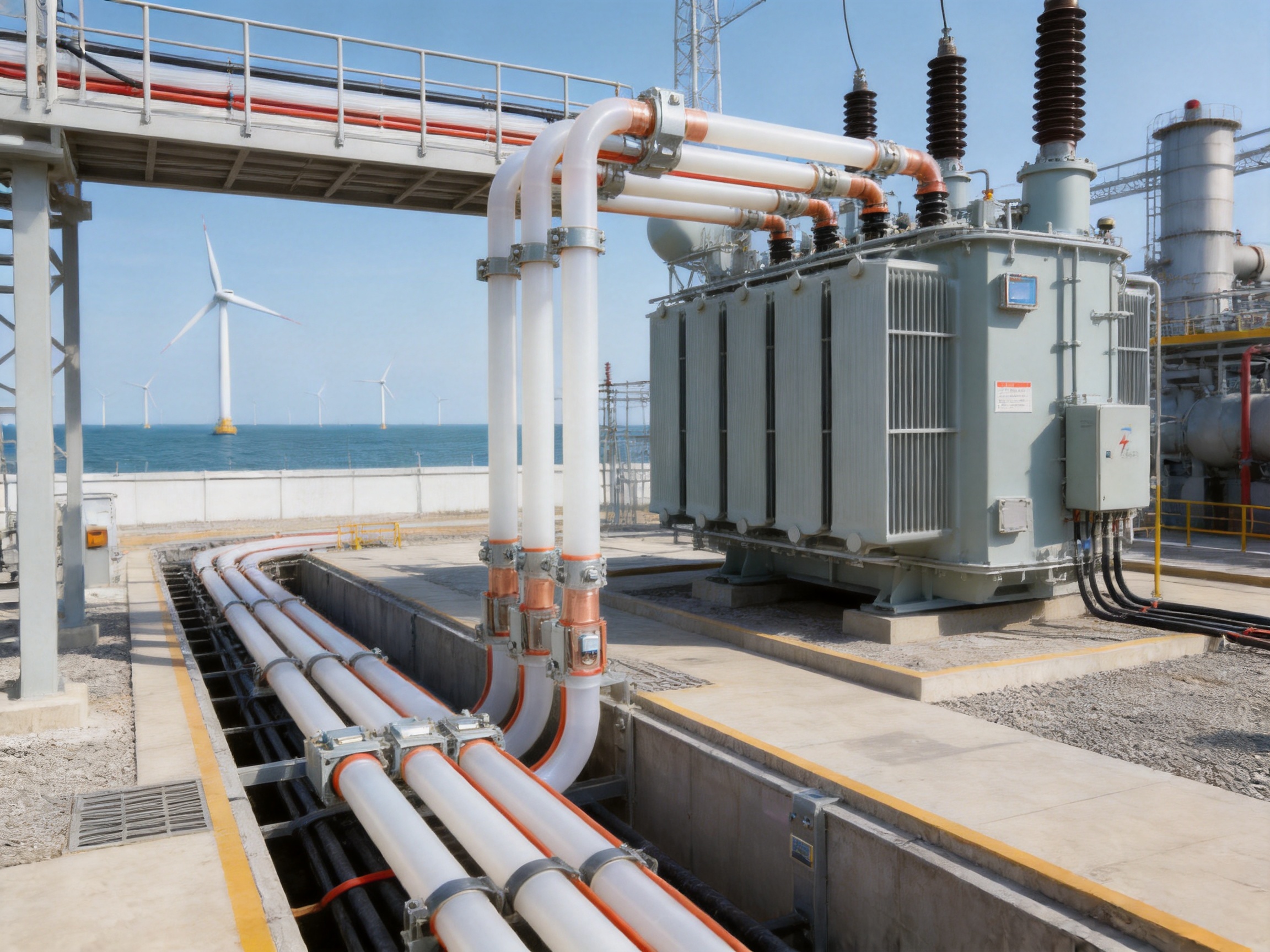
PTFE tubular bus bar is a specialized power transmission product developed for electrical systems that require strong insulation, high dielectric reliability, corrosion resistance, and stable operation across a wide temperature range. By combining a copper or aluminum conductor with a precision-engineered polytetrafluoroethylene insulation system, this type of tubular bus bar provides a practical solution for demanding power distribution environments.
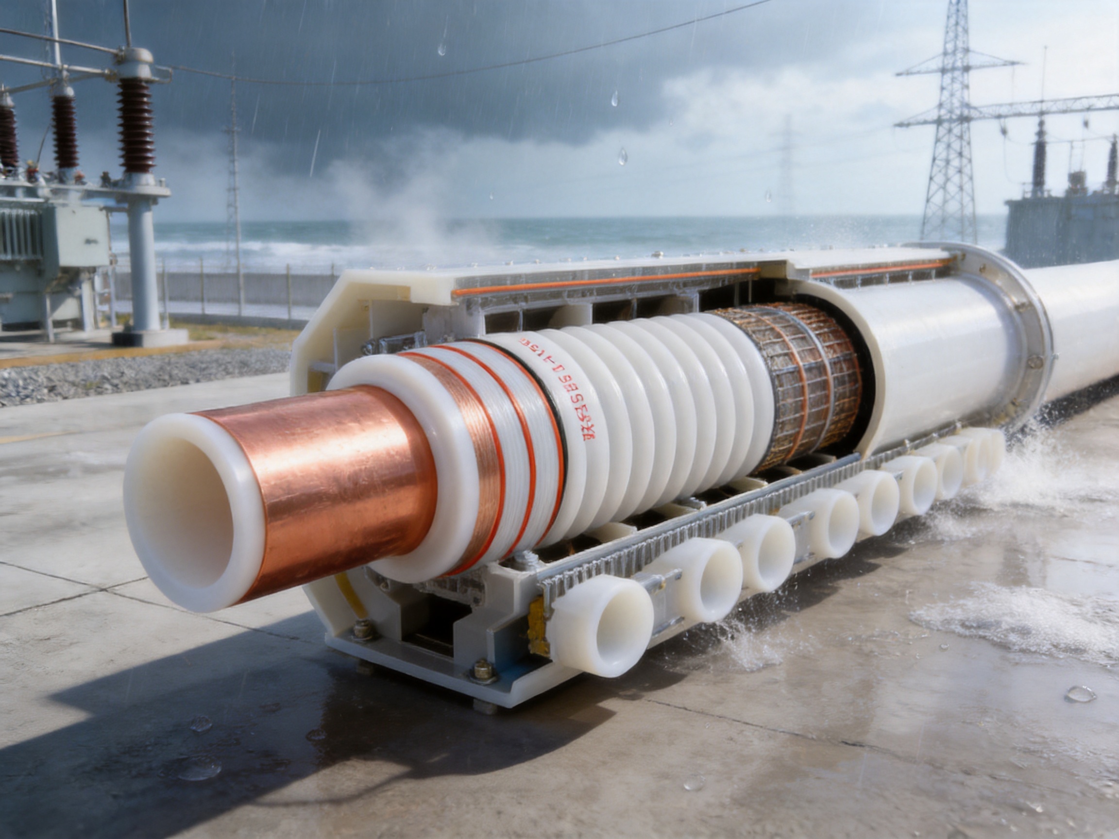
Unlike conventional bare busbars, cable assemblies, or lower-performance insulated busbar designs, PTFE tubular bus bar is engineered to control electric fields, minimize insulation defects, and maintain reliable operation under severe thermal, chemical, mechanical, and environmental conditions. Its structure can incorporate multiple capacitive screens, including zero screens, grading screens, and grounding screens, together with silicone rubber creepage extenders. These features improve electric field distribution and enhance resistance to surface tracking and external contamination.
The product is particularly suitable for specialized high-voltage and medium-voltage applications, outdoor substations, industrial facilities, coastal installations, chemical plants, power generation projects, wind energy systems, and locations exposed to extreme cold, high heat, humidity, salt spray, or corrosive substances. Depending on the system design, the tubular bus bar can be configured for different conductor materials, dimensions, insulation thicknesses, connection methods, and installation routes.
Jiangsu Wopeng Power Technology Co., Ltd. combines product engineering, precision manufacturing, testing capability, and project support to supply insulated busbar systems for demanding electrical infrastructure. The company’s experience covers high- and low-voltage tubular busbars, epoxy resin vacuum-cast tube busbars, copper and aluminum busbars, wind power busbars, compact busbar systems, and sliding contact line systems.
1. What Is a PTFE Tubular Bus Bar?
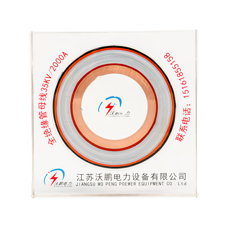
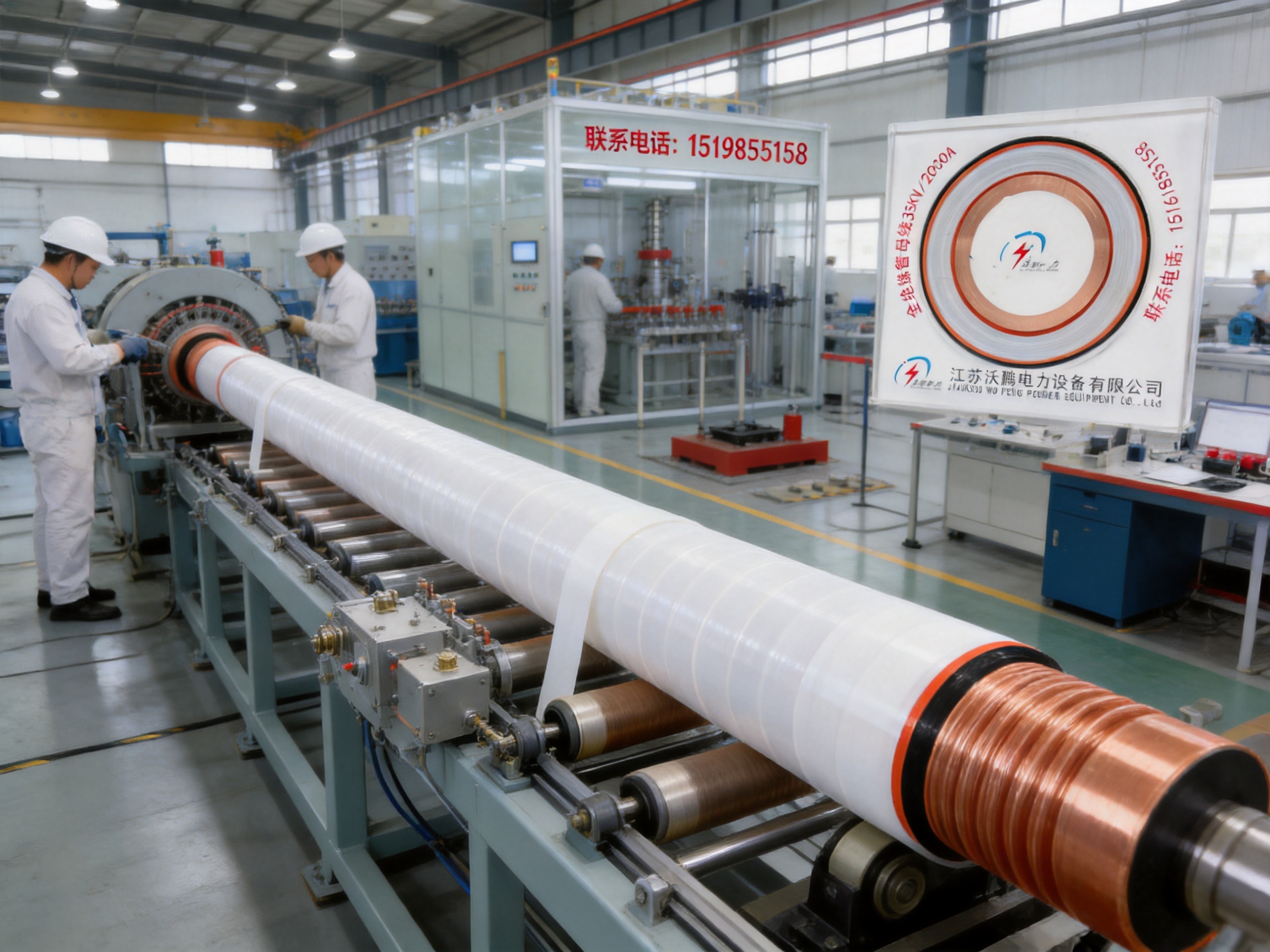
A PTFE tubular bus bar is an insulated tubular conductor used to transmit and distribute electrical power. Its main structure consists of a metal conductor core, a carefully applied PTFE insulation system, electrical shielding layers, sealing or protection components, and connection fittings. The conductor may be manufactured from copper or aluminum according to the required current rating, weight, conductivity, mechanical strength, and project budget.
PTFE, also known as polytetrafluoroethylene, is a fluoropolymer recognized for its high chemical resistance, low friction coefficient, low dielectric loss, non-stick surface, and broad thermal operating capability. When processed correctly, PTFE provides a stable insulation barrier around the conductor. The insulation can be formed through controlled mechanical winding of PTFE film, with silicone oil applied between layers to create a dense, continuous, and low-void dielectric structure.
The term “tubular bus bar” describes the physical form of the conductor and insulation assembly. Compared with a flat busbar, the tubular design can provide improved mechanical symmetry, better field distribution, and flexible routing through complex electrical installations. The circular or engineered tubular geometry is also suitable for enclosed, semi-enclosed, and fully insulated systems.
For specialized designs, the PTFE insulation system may be combined with no fewer than five capacitive screens. These screens can include a zero screen, grading screens, and a grounding screen. Their purpose is to manage electrical stress at the conductor surface, distribute voltage more evenly through the insulation, control partial discharge risk, and provide a defined path for shielding and grounding.
Silicone rubber creepage extenders may be installed on the external surface. They increase the effective creepage distance and improve performance when the bus bar is exposed to moisture, pollution, condensation, dust, salt deposits, or industrial contaminants. This is particularly important in outdoor substations, coastal areas, and process industries.
Core Structure
The conductor core is the primary current-carrying element. Copper offers high electrical conductivity and strong short-circuit performance, while aluminum offers lower weight and potentially reduced material cost. The selection depends on the required continuous current, short-time withstand current, voltage level, thermal conditions, installation distance, mechanical support, and connection design.
The PTFE insulation layer is applied with strict process control. The winding tension must remain consistent so that the film layers do not loosen, wrinkle, overlap irregularly, or form local stress concentrations. For high-performance designs, the inter-layer tension requirement may be controlled within approximately ±2 percent. Ultrasonic assistance or other bubble-control methods can be used to reduce voids and improve the continuity of the insulation.
Electrical screens are positioned around the insulation system according to the required field-control design. These layers are not decorative components. They are functional parts of the dielectric system and must be manufactured, connected, and grounded correctly. Poor screen continuity or incorrect grounding can compromise the expected electrical performance of the entire assembly.
The external protection system may include silicone rubber, protective sheathing, creepage extenders, sealing components, and mechanical supports. These components protect the insulation from environmental exposure and help maintain the required creepage distance over the service life of the equipment.
PTFE Tubular Bus Bar
2. Why PTFE Is Suitable for Severe Electrical Environments
Electrical equipment installed in extreme environments faces more than one type of stress. High voltage creates electrical stress, temperature changes produce expansion and contraction, humidity can reduce surface insulation performance, and chemical contaminants can attack conventional materials. Mechanical vibration, dust, salt spray, and ultraviolet exposure may create additional risks.
PTFE addresses many of these challenges through a combination of material properties. It is highly resistant to acids, alkalis, salt spray, and many organic solvents. It also maintains stable insulation characteristics over a wide operating temperature range. The product information for this design indicates an operating range from approximately -60°C to 250°C, while specific electrical configurations may be rated according to project requirements and applicable standards.
Temperature Resistance
Temperature stability is one of the most important advantages of PTFE tubular bus bar. In cold regions, insulation materials may become brittle, contract, or lose mechanical flexibility. In hot locations, conventional insulation may soften, age quickly, or experience accelerated dielectric degradation. PTFE is able to maintain useful performance across a broad temperature range, making it suitable for outdoor substations, industrial furnaces, power plants, wind turbines, and other installations exposed to temperature variation.
The actual permissible operating temperature depends on the conductor material, current loading, thermal dissipation, support spacing, connection hardware, ambient conditions, and system design. A properly engineered busbar system must therefore be evaluated as a complete assembly rather than according to the insulation material alone.
Chemical and Corrosion Resistance
Many electrical systems operate in areas where corrosive substances are present. Chemical plants may contain acids, solvents, and alkaline vapors. Coastal installations may experience salt spray and high humidity. Wastewater treatment facilities can expose electrical components to corrosive gases. Mining and heavy manufacturing sites may create dust and chemical contamination.
PTFE is chemically inert against a broad range of substances. This reduces the likelihood that the insulation will become swollen, cracked, softened, or chemically weakened. The result is improved long-term stability when compared with insulation materials that are more sensitive to particular chemicals.
Corrosion resistance also reduces maintenance pressure. If the external insulation remains stable and the electrical field remains properly controlled, the inspection interval and cleaning burden may be reduced. Nevertheless, regular inspection remains necessary, especially where the busbar is exposed to conductive deposits or mechanical damage.
Low Friction and Mechanical Stress Reduction
PTFE has an extremely low friction coefficient. In a wound insulation system, this property helps reduce friction-related mechanical stress during controlled processing. It can also be advantageous where thermal expansion, vibration, or movement must be accommodated in the insulation structure.
Low friction does not mean that the insulation can be installed without mechanical supports. The busbar still requires appropriate fixing, bending control, connection alignment, and short-circuit restraint. Its low-friction behavior should be considered as one part of the overall mechanical design.
High Dielectric Strength
PTFE provides high dielectric strength and a low dielectric constant. The product information indicates a breakdown voltage of approximately 35 kV/mm or higher for the specified configuration. Actual performance depends on insulation thickness, winding quality, screen configuration, test conditions, temperature, humidity, conductor geometry, and manufacturing quality.
A low dielectric loss factor is also beneficial. The supplied technical information identifies a dielectric loss factor of no more than approximately 0.0002 at 50 Hz for the stated design data. Low dielectric loss can help reduce energy dissipation in the insulation and support stable operation in high-voltage systems.
3. Main Technical Advantages
Dense, Continuous Insulation
The use of mechanically wound PTFE film with silicone oil between layers is intended to form a dense, continuous insulation structure with minimal gas inclusion. Voids and air pockets can produce local electric-field intensification and increase the risk of partial discharge. Through controlled winding and bubble-management procedures, the insulation system can achieve improved uniformity.
Manufacturing consistency is essential. PTFE film must be applied with stable tension, controlled overlap, and accurate positioning. The production environment, film quality, winding speed, equipment calibration, and operator training all influence the finished result.
Electric Field Control
High-voltage insulation cannot rely only on material thickness. The electric field must also be controlled at interfaces, ends, connection points, bends, and changes in geometry. Capacitive screens help distribute voltage across the insulation and reduce localized stress.
A design containing multiple screens can provide more precise control than a simple single-layer shield. The zero screen, grading screens, and grounding screen each contribute to the overall field-control strategy. Their arrangement must be matched to the rated voltage, conductor dimensions, insulation thickness, termination design, and installation environment.
Enhanced Creepage Performance
Clearance is the shortest distance through air between conductive components, while creepage is the shortest distance along an insulating surface. In humid or polluted conditions, surface contamination can create a conductive path. Silicone rubber creepage extenders increase the effective surface distance and help reduce the risk of tracking.
This feature is especially valuable for outdoor installations, coastal substations, industrial plants, and systems installed in dusty or humid areas. The external surface should still be kept in suitable condition through inspection and maintenance, because severe contamination can eventually reduce the effectiveness of any creepage design.
High Protection Capability
The product configuration can achieve a protection rating of up to IP68, depending on the complete assembly and sealing design. This level of protection indicates strong resistance to dust ingress and water penetration under defined test conditions. IP protection is valuable in environments where the busbar may be exposed to rain, splash, washdown procedures, temporary immersion, or airborne dust.
The protection rating applies to the finished system, including joints, end fittings, inspection points, and connection interfaces. Therefore, installation quality is as important as factory production. Improperly sealed joints or damaged protective components can reduce the effective protection level.
4. Comparison with Other Insulated Busbar Technologies
PTFE tubular bus bar competes with several other insulated busbar technologies, including epoxy resin cast busbars, silicone rubber insulated busbars, conventional cable systems, and bare or semi-insulated tubular conductors. No single product is ideal for every application. The correct choice depends on electrical rating, environment, installation route, maintenance requirements, mechanical conditions, and total lifecycle cost.
| Characteristic | PTFE Tubular Bus Bar | Epoxy Resin Cast Bus Bar | Silicone Rubber Insulated Bus Bar | Conventional Cable System |
|---|---|---|---|---|
| Typical insulation approach | Precision-wound PTFE film with screens | Vacuum-cast or molded epoxy insulation | Elastomeric silicone rubber insulation | Layered polymer cable insulation with shield |
| Temperature capability | Approximately -60°C to 250°C for the stated product configuration | Approximately -30°C to 130°C for typical designs | Approximately -40°C to 120°C for typical designs | Depends on cable insulation and conductor class |
| Chemical resistance | Excellent against many acids, alkalis, salts, and solvents | Good, but dependent on resin formulation and exposure | Good against weathering and moisture; chemical compatibility varies | Depends on polymer jacket and installation environment |
| Electric field control | Multiple capacitive screens can be integrated | Can include embedded screens and molded field control | Usually uses an external shield or conductive layer | Normally uses a metallic screen or shield |
| Mechanical form | Rigid or semi-rigid tubular assembly | Rigid molded assembly | Flexible or semi-flexible depending on design | Flexible and suitable for long cable routes |
| Installation appearance | Organized and compact tubular route | Compact and clean | Flexible and adaptable | May require cable trays, supports, and larger bending spaces |
| Special environmental suitability | Very strong for extreme temperature and chemical environments | Strong for many indoor and outdoor power installations | Strong for flexibility and weather exposure | Strong where flexible routing and long-distance cable installation are required |
Compared with epoxy resin cast busbars, PTFE tubular bus bar generally offers a wider temperature range and stronger resistance to a broad selection of corrosive chemicals. Epoxy systems, however, can provide excellent rigidity, dimensional stability, and cost efficiency for many conventional medium-voltage installations.
Compared with silicone rubber insulation, PTFE offers higher chemical inertness and a particularly low dielectric loss. Silicone rubber may provide greater flexibility and better tolerance of repeated movement. The choice depends on whether the installation prioritizes extreme chemical and thermal stability or flexibility and movement accommodation.
Compared with conventional cables, a tubular busbar can provide a more organized high-current route, a defined mechanical structure, and simplified access to selected connection points. Cables remain highly advantageous for flexible routing, long-distance distribution, and systems requiring frequent changes in direction or movement.
The main limitation of PTFE tubular bus bar is cost. PTFE film and specialized processing equipment are more expensive than many conventional insulation materials. The winding process also requires strict quality control, specialized personnel, and careful inspection. For this reason, PTFE is most valuable when its environmental and electrical advantages justify the additional investment.
5. Manufacturing Process and Quality Control
The performance of PTFE tubular bus bar is determined not only by its material selection but also by the manufacturing process. A high-quality product requires coordinated control of conductor preparation, insulation winding, screen installation, end treatment, sealing, mechanical assembly, and final testing.
Engineering and Configuration Review
Production begins with a technical review of the project requirements. Engineers evaluate rated voltage, continuous current, short-circuit withstand requirements, conductor material, conductor cross-section, insulation thickness, creepage distance, installation route, bending requirements, joint arrangement, grounding method, ambient temperature, pollution level, and protection rating.
For custom products, the engineering team may also review transformer terminals, switchgear interfaces, support spacing, expansion requirements, cable trench dimensions, cable mezzanines, and connection clearances. The objective is to ensure that the busbar is designed as part of the complete electrical system rather than as an isolated component.
Conductor Preparation
Copper or aluminum conductor components are prepared according to approved drawings and dimensional requirements. CNC machining can be used to produce accurate holes, slots, end profiles, connection surfaces, and mounting features. The conductor surface is inspected for burrs, sharp edges, contamination, and dimensional deviations before insulation is applied.
Sharp edges can create stress concentrations in the insulation. They may also damage PTFE film during winding or reduce the effective dielectric distance. For this reason, edge treatment and surface preparation are important parts of the process.
PTFE Film Winding
PTFE film winding is one of the most technically demanding steps. The film must be applied at controlled tension and with a consistent overlap. Uneven tension can lead to wrinkles, loose layers, excessive compression, or local gaps. The winding equipment must maintain a stable speed and alignment throughout the process.
The inter-layer tension requirement may be controlled within approximately ±2 percent for demanding designs. This level of control helps provide uniform insulation density and repeatable electrical performance. In-process checks can be used to monitor film position, overlap, winding tension, and surface condition.
Because PTFE has low surface energy, direct bonding between layers can be difficult. Special treatment agents or surface preparation methods may be required to improve inter-layer interaction. The selected treatment must be compatible with the intended electrical, thermal, and environmental performance of the product.
Void and Bubble Control
Gas pockets and voids are potential sources of partial discharge. The manufacturing process therefore aims to minimize trapped air and maintain close contact between film layers. Ultrasonic assistance or comparable process technology can be used to support bubble control.
Bubble-control procedures may be combined with controlled application of silicone oil between layers. The objective is to produce a dense, gas-free or substantially low-void continuous insulation structure. This process requires clean materials, stable equipment, and controlled handling throughout production.
Screen Installation
Capacitive screens are installed according to the approved electrical design. Their dimensions, continuity, overlap, termination, and grounding connections must be controlled carefully. A screen that is displaced, interrupted, or incorrectly connected can affect the electric-field distribution and compromise the designed insulation performance.
Screen installation is verified through visual inspection, dimensional checks, continuity tests, and electrical tests where applicable. The grounding screen must be connected in accordance with the system grounding plan. Special attention is required at joints, terminations, bends, and transitions between different structural sections.
External Protection and Creepage Extenders
Silicone rubber creepage extenders and external protection components are installed after the primary insulation and screen system have been completed. Their spacing and profile are selected to meet the required creepage distance and environmental performance.
The external surface must be free from cuts, cracks, contamination, and manufacturing defects. Sealing components are checked at interfaces and end sections. Where the product is designed for a high IP rating, the integrity of every joint and sealing surface is important.
CNC Machining and Automated Assembly
Advanced manufacturing systems support dimensional consistency and repeatability. CNC machining equipment can manufacture conductor components and connection parts with accurate tolerances. Automated or semi-automated assembly technologies can improve alignment, reduce manual variation, and support stable production efficiency.
Modern production lines also help establish traceability. Materials, process parameters, inspection results, and final test records can be associated with production batches or individual assemblies. This information supports quality management, project documentation, and after-sales service.
6. Testing and Inspection
Electrical testing is essential for verifying the safety and reliability of PTFE tubular bus bar. The exact test program depends on the rated voltage, product configuration, customer specification, and applicable standards. A typical quality program may include material inspection, dimensional inspection, insulation resistance testing, high-voltage withstand testing, partial discharge evaluation, screen continuity testing, mechanical verification, sealing inspection, and routine final checks.
Insulation Resistance Testing
Insulation resistance testing evaluates the resistance between the conductor and the shielding or grounding system. The supplied product data identifies insulation resistance above approximately 1.0 × 10¹⁴ ohms for the specified design. The actual measured value depends on test voltage, temperature, humidity, insulation geometry, and test duration.
Insulation resistance testing helps identify contamination, moisture ingress, incorrect screen connections, insulation damage, or assembly defects. It should be performed using calibrated equipment and controlled procedures.
High-Voltage Withstand Testing
High-voltage withstand testing applies a specified test voltage for a defined period to confirm that the insulation can tolerate the required electrical stress without breakdown or flashover. This test is particularly important for medium- and high-voltage busbar assemblies.
The test voltage and duration must be determined according to the rated system voltage and applicable technical requirements. Testing must be performed in a controlled area by qualified personnel, with suitable safety interlocks and grounding procedures.
Partial Discharge Evaluation
Partial discharge testing can help identify localized insulation defects, voids, sharp field concentrations, or screen irregularities. A low-void winding process and precise field control are intended to reduce partial discharge activity.
For projects with strict high-voltage requirements, partial discharge test data can provide important evidence of insulation quality. It can also support comparisons between production batches and help identify process trends before they become serious defects.
Mechanical Verification
Mechanical checks confirm conductor dimensions, joint alignment, support interfaces, bending geometry, mounting points, and connection surfaces. The busbar must withstand transportation, installation, thermal expansion, electromagnetic forces during short circuits, and normal operational vibration.
Although PTFE provides excellent insulation properties, the complete busbar assembly still requires correct mechanical design. Support spacing, fixing hardware, bend radius, and connection torque must be specified and followed during installation.
Routine Quality Management
Jiangsu Wopeng Power Technology operates a quality management system supported by standardized inspection procedures. Products can undergo high-voltage tests, insulation tests, mechanical verification, dimensional checks, and routine production inspections. Collaboration with third-party testing institutions can provide additional independent validation for selected projects.
A disciplined quality system is especially important for PTFE products because many performance characteristics depend on process control. The final product may appear visually acceptable even when an internal winding or screen defect exists. Comprehensive testing therefore complements visual inspection and manufacturing experience.
7. Application Solutions
PTFE tubular bus bar can be integrated into several common power distribution arrangements. The preferred route depends on the position of the main transformer, control room, switchgear, cable trench, cable mezzanine, equipment foundation, and maintenance access points.
Transformer-to-Switchgear Connection
One of the most common applications is the connection between the low-voltage terminals of a main transformer and the incoming terminals of a switch cabinet. The tubular busbar provides a direct, organized, and high-current connection between the two pieces of equipment.
This arrangement can improve visual order and reduce the number of parallel cable runs. It may be suitable for high-current transformer outputs where a compact, engineered connection is preferred. The busbar can be designed as a fully insulated or semi-insulated system according to the electrical and environmental requirements.
During design, engineers must verify transformer terminal dimensions, switchgear entry position, phase spacing, support points, thermal expansion, and short-circuit forces. Flexible expansion sections or specially designed joints may be necessary where equipment movement or differential expansion is expected.
Routing Through Cable Trenches
A tubular busbar can be routed through an underground cable trench and connected to switch cabinets or other electrical equipment. This method is particularly useful when direct overhead routing is impractical or when the project requires protected underground distribution.
The trench must provide sufficient clearance, drainage, support, ventilation, and access for installation and inspection. Water accumulation should be avoided, even when the product has a high protection rating. The busbar should be supported so that it does not rest directly on the trench floor or experience unnecessary mechanical stress.
Routing Through Cable Mezzanines
Cable mezzanines provide an elevated route between switch cabinets, transformers, and other electrical equipment. Tubular busbars can be installed through these spaces to create a compact and orderly distribution path.
This method can reduce congestion in the main equipment area and separate power transmission routes from control wiring. It is suitable for projects where floor-level cable routes are crowded or where the electrical design requires a dedicated elevated connection.
Top and Bottom Switchgear Connections
Switch cabinets may be designed with top-entry or bottom-entry connections. Tubular busbar systems can be configured for either arrangement, allowing users to select the connection method according to the building structure, cable trench position, maintenance plan, and equipment layout.
Top connections may simplify routes through upper cable spaces, while bottom connections may be convenient where cable trenches or basement routes are already available. The selected arrangement should maintain required clearances and provide enough room for joint assembly and future maintenance.
Wind Power and Renewable Energy Installations
Wind turbines and renewable energy facilities require electrical components that can tolerate vibration, temperature variation, humidity, and restricted installation spaces. Tubular busbar systems can be adapted for generator-to-transformer connections, tower sections, converter cabinets, and other high-current routes.
For wind turbine applications, the mechanical design must account for vibration, movement, transportation constraints, and assembly inside the tower. The insulation and external protection system must also be selected according to the temperature, humidity, and contamination conditions of the site.
Intelligent Monitoring Systems
Modern tubular busbar systems can be integrated with monitoring solutions. A monitoring system may collect information related to temperature, insulation condition, current, voltage, partial discharge, grounding status, or other operating parameters.
Intelligent monitoring supports condition-based maintenance. Instead of relying only on fixed inspection intervals, operators can analyze operating trends and identify unusual temperature increases, insulation changes, or connection abnormalities. The exact sensors and communication architecture depend on the project requirements.
8. Advantages of Working with an Experienced Manufacturer
Selecting the right manufacturer is as important as selecting the insulation material. PTFE tubular bus bar is a customized electrical product, and its performance depends on coordinated design, process control, testing, and installation support.
Engineering Capability
An experienced manufacturer can review the electrical and mechanical interface between the busbar and adjacent equipment. This includes transformer terminals, switchgear compartments, grounding systems, support structures, cable trenches, cable mezzanines, and maintenance access.
Engineering support is particularly valuable for non-standard routes, complex bends, multiple connection points, mixed conductor sizes, and installations with strict clearance requirements. A manufacturer with experience in several busbar technologies can also recommend whether PTFE, epoxy resin, silicone rubber, aluminum, copper, or another configuration is most suitable.
Custom Manufacturing
Custom PTFE tubular busbars can be produced for specific conductor sizes, insulation thicknesses, voltage levels, current ratings, lengths, screen structures, termination types, and installation routes. Customization may also include special mounting brackets, expansion joints, grounding connections, inspection features, and protection arrangements.
Accurate customization reduces field modification. This is important because cutting, drilling, or altering an insulated busbar at the installation site may damage the insulation system or change the electric-field distribution. Factory-controlled production provides better repeatability and documentation.
Integrated Product Portfolio
Jiangsu Wopeng Power Technology has a product portfolio that includes 35kV epoxy resin vacuum-cast tubular busbars, low-voltage epoxy-cast busbar trunking, copper and aluminum tubular busbars, wind power tubular busbars, compact busbar systems, and sliding contact line systems.
This broad product range allows the company to support different sections of the same project. A customer may require PTFE tubular busbar in one extreme environment, epoxy resin cast busbar in a conventional medium-voltage area, and low-voltage busway in a building distribution section. Access to multiple technologies can simplify coordination and technical communication.
Production and Testing Infrastructure
The company operates modern production lines equipped with vacuum casting systems, CNC machining equipment, and automated assembly technologies. These facilities support dimensional precision, stable assembly, and repeatable production processes.
Manufacturing is supported by high-voltage testing, insulation testing, mechanical verification, and routine quality inspection. Where required, collaboration with independent third-party testing institutions can provide additional validation of product performance.
Project Experience
Founded in 2018, Jiangsu Wopeng Power Technology focuses on the development and manufacture of high- and low-voltage busbar systems. Its products operate across more than 17 provinces and serve power generation, substations, wind energy, industrial manufacturing, rail transit, and large commercial facilities.
Project experience contributes to practical product design. Electrical equipment must be transported, installed, connected, inspected, and maintained under real site conditions. Experience with different industries helps the engineering team identify common installation challenges before production begins.
9. Design Considerations Before Ordering
Customers should provide complete technical information when requesting a PTFE tubular busbar quotation or design proposal. Incomplete information may result in unsuitable dimensions, connection details, or installation assumptions.
Electrical Requirements
The required rated voltage, continuous current, frequency, short-circuit withstand current, insulation level, lightning impulse withstand level, and grounding method should be defined. The system voltage should be confirmed together with the applicable national, international, utility, or project standards.
Conductor Selection
Copper and aluminum conductors have different electrical, thermal, mechanical, and economic characteristics. Copper generally provides higher conductivity and compact dimensions. Aluminum can reduce weight and may be more economical for large cross-sections. The manufacturer can evaluate the most appropriate option based on the current rating and installation conditions.
Environmental Conditions
Information should include minimum and maximum ambient temperature, humidity, altitude, pollution level, salt exposure, chemical exposure, ultraviolet exposure, dust, water contact, indoor or outdoor installation, and expected cleaning or washdown procedures.
Environmental data is necessary for selecting insulation thickness, creepage extenders, external protection, sealing arrangements, and monitoring requirements. An installation exposed to coastal salt spray may require different external protection from an indoor switchgear room.
Mechanical and Routing Requirements
Drawings should identify the route length, bends, elevation changes, support points, expansion gaps, equipment interfaces, cable trench dimensions, mezzanine clearances, and access restrictions. The manufacturer may request three-dimensional layout information for complex routes.
Connection details should include flange dimensions, bolt patterns, terminal orientation, phase arrangement, grounding points, and required joint locations. Accurate interface data can significantly reduce installation time.
Maintenance and Monitoring
The design should consider how the busbar will be inspected and maintained. Access panels, removable covers, temperature sensors, grounding test points, and monitoring interfaces can be incorporated where appropriate.
If the customer intends to use a digital monitoring platform, the required communication protocol, sensor output, alarm thresholds, and data storage method should be discussed during the design stage.
10. Installation and Maintenance Recommendations
Installation should be performed by qualified electrical personnel in accordance with approved drawings and safety procedures. The busbar should be inspected after transportation and before installation. Any damage to the external insulation, sealing components, screens, connection surfaces, or support parts should be recorded and reviewed before energization.
During installation, the busbar should not be dragged across rough surfaces or lifted from unsuitable points. Bending, twisting, impact, and excessive force can damage the insulation system even when the damage is not immediately visible.
Connection surfaces must be clean and correctly aligned. Bolts should be tightened using the specified torque. Incorrect torque can cause overheating, mechanical loosening, or damage to connection components. Grounding screens and external protective components must be connected according to the approved electrical drawings.
Before energization, the completed system should undergo the required insulation resistance, continuity, high-voltage, grounding, and functional checks. Test records should be retained as part of the project documentation.
Routine maintenance should include visual inspection for contamination, cracks, mechanical damage, corrosion, loose supports, water accumulation, and abnormal discoloration. Thermal imaging can help identify overloaded or loose connections. Monitoring data can be reviewed for trends in temperature, current, insulation condition, or partial discharge.
Cleaning methods must be compatible with PTFE, silicone rubber, sealing materials, and other external components. Strong chemicals should not be applied without confirmation of compatibility. Maintenance personnel should also inspect creepage extenders and verify that they remain correctly positioned and free from severe contamination.
11. Cost, Lifecycle Value, and Sustainability
PTFE tubular bus bar generally has a higher initial cost than many conventional insulated busbar products. PTFE raw material is expensive, and the winding process requires specialized equipment, strict tension control, bubble-management procedures, screen installation, and comprehensive testing.
However, the initial purchase price is only one part of the lifecycle cost. In an extreme environment, premature insulation aging, corrosion, contamination, unplanned shutdowns, and frequent maintenance can create significant operating expenses. A product with stronger environmental resistance may reduce the frequency of replacement and improve operational continuity.
The compact and organized form of a tubular busbar can also reduce installation complexity in high-current applications. A factory-engineered assembly may require less site modification than a collection of parallel cables, supports, and field-installed accessories.
PTFE is difficult to degrade and recycle. This creates environmental processing challenges at the end of the product’s service life. Responsible project planning should therefore consider material recovery, separation of conductor and insulation components, and compliant waste handling. Manufacturers and customers should evaluate end-of-life procedures as part of the total product lifecycle.
Although PTFE presents recycling challenges, its long service life and resistance to harsh conditions may reduce the frequency of replacement. A lifecycle assessment should compare material production, transportation, maintenance, energy losses, service life, and end-of-life treatment rather than focusing only on recyclability.
12. Technical Challenges and How They Are Managed
Winding Process Control
Uniform winding tension is a critical manufacturing challenge. If tension is too low, layers may become loose or form gaps. If tension is too high, the film may stretch, deform, or create excessive mechanical stress. Automated tension control, calibrated equipment, and in-process inspection help reduce variation.
Inter-Layer Adhesion
PTFE has a low surface energy, which makes inter-layer bonding difficult. Special treatment agents and controlled surface preparation may be required. The treatment process must be carefully managed so that it improves structural integrity without introducing contamination or reducing electrical performance.
Void Reduction
Voids can increase electrical stress and partial discharge risk. Controlled application of silicone oil, ultrasonic assistance, clean-room-style handling where appropriate, and carefully controlled winding parameters can help reduce trapped gas.
High Material Cost
PTFE material cost is higher than that of many standard insulation materials. To control the total cost, manufacturers can optimize conductor dimensions, film usage, screen configuration, production scheduling, and standardized component design while maintaining the specified performance.
Difficult Recycling
PTFE insulation must be handled separately from copper, aluminum, steel, silicone rubber, and other components during disposal. Clear product documentation and end-of-life guidance can help customers plan responsible processing.
13. Recommended Industries and Use Cases
PTFE tubular bus bar is well suited to power generation facilities where high current, heat, vibration, and reliability are important. It can be considered for transformer connections, generator output systems, auxiliary power distribution, and specialized equipment interfaces.
Substations may use the product for connections between transformers, switchgear, control rooms, and cable routes. Outdoor and coastal substations can benefit from chemical resistance, high creepage performance, and sealed construction.
Chemical and petrochemical facilities may require insulation that remains stable in the presence of corrosive vapors and solvents. The suitability of PTFE must be confirmed against the exact chemical composition, concentration, temperature, and exposure duration at the site.
Wind power systems may use tubular busbars in nacelles, towers, converter systems, and transformer connections. The design should account for vibration, transportation, installation access, and thermal cycling.
Rail transit projects and large commercial buildings may use tubular or compact busbar systems where organized routing, high current capacity, and space efficiency are priorities. The selection between PTFE, epoxy resin, and other technologies should be based on the specific voltage, current, environmental, and structural requirements.
14. Frequently Asked Questions
Q1: What is the main advantage of PTFE tubular bus bar?
The main advantage is the combination of high dielectric performance, broad temperature capability, strong chemical resistance, low dielectric loss, and controlled electric-field distribution. These properties make it suitable for electrical systems operating in severe environments.
Q2: What conductor materials can be used?
Copper and aluminum are the primary conductor options. Copper is often selected for high conductivity and compact dimensions, while aluminum can reduce weight and material cost. The final selection should consider current rating, thermal performance, mechanical requirements, and project economics.
Q3: What temperature range can the product withstand?
The supplied product information indicates an operating range from approximately -60°C to 250°C for the stated PTFE design. Specific ratings must be confirmed for the complete assembly because conductor heating, connection components, external protection, current loading, and installation conditions also influence the permissible temperature.
Q4: Is PTFE tubular bus bar suitable for outdoor applications?
Yes. Its resistance to moisture, corrosion, temperature variation, and contamination makes it suitable for many outdoor applications. The external protection, creepage distance, sealing, ultraviolet exposure, and installation support must be designed according to the site conditions.
Q5: Can the product achieve IP68 protection?
The product configuration can reach a protection rating of up to IP68 when the complete assembly, joints, seals, and connection interfaces are correctly designed and manufactured. Installation quality is essential to maintaining the intended protection level.
Q6: How are electric fields controlled?
Electric fields are controlled through the tubular geometry, insulation thickness, capacitive screens, grading screens, zero screens, and grounding screens. The screen arrangement is engineered according to the voltage level, conductor structure, insulation system, and termination design.
Q7: Can PTFE tubular bus bar be customized?
Yes. Customization may include conductor material, conductor size, insulation thickness, length, bend geometry, screen arrangement, terminal design, creepage extenders, grounding points, supports, sealing features, monitoring interfaces, and installation route.
Q8: Is PTFE tubular bus bar more expensive than epoxy resin busbar?
It is generally more expensive because PTFE raw material and specialized winding processes have higher costs. However, the additional investment may be justified where extreme temperature capability, chemical resistance, low dielectric loss, or long-term environmental stability is required.
Q9: How long can PTFE tubular bus bar operate?
The supplied technical information indicates a potential service life of approximately 35 to 45 years under normal high-voltage working conditions. Actual service life depends on electrical loading, temperature, environmental exposure, mechanical conditions, installation quality, maintenance, and compliance with operating limits.
Q10: What information is required for a quotation?
Important information includes rated voltage, continuous current, conductor material, short-circuit requirements, route length, dimensions, bend requirements, connection drawings, installation environment, temperature range, pollution level, protection rating, grounding method, quantity, and required testing or certification.
Q11: Can the busbar be installed in a cable trench?
Yes. It can be routed through cable trenches or cable mezzanines and connected to switch cabinets or other equipment. The route must provide sufficient clearance, mechanical support, drainage, access, and protection from impact.
Q12: Is monitoring available?
Monitoring systems can be developed or integrated to collect selected operating data such as temperature, current, voltage, insulation condition, grounding status, or partial discharge. The monitoring functions should be specified during the engineering stage.
15. Why Choose Jiangsu Wopeng Power Technology
Jiangsu Wopeng Power Technology Co., Ltd. is a specialized high-tech enterprise focused on the development and manufacture of high- and low-voltage busbar systems. Since its establishment in 2018, the company has developed products for power generation, substations, wind energy, industrial manufacturing, rail transit, commercial facilities, and other infrastructure applications.
The company’s strengths include engineering customization, modern production equipment, experienced technical personnel, standardized inspection, and an extensive busbar product portfolio. Its facilities include vacuum casting systems, CNC machining equipment, and automated assembly technologies that support repeatable manufacturing.
Wopeng’s product range covers 35kV epoxy resin vacuum-cast tubular busbars, low-voltage epoxy-cast busbar trunking, copper and aluminum tubular busbars, wind power tubular busbars, compact busbar systems, sliding contact line systems, and specialized insulated tubular busbars such as PTFE configurations.
The company supports customers from technical review and product design through manufacturing, testing, delivery, and application support. This integrated approach helps reduce interface errors and allows the product to be adapted to actual project conditions.
For customers requiring a PTFE tubular busbar supplier, the most important evaluation factors include process capability, insulation testing, electric-field design, customization experience, documentation quality, production traceability, and after-sales technical support. Wopeng’s engineering and manufacturing resources are structured to address these requirements.
16. Conclusion
PTFE tubular bus bar is a high-performance solution for power transmission systems that operate beyond the comfortable range of conventional insulation materials. Its precision-wound PTFE film insulation, silicone oil-assisted layer structure, multiple capacitive screens, silicone rubber creepage extenders, and high protection capability provide a strong foundation for reliable service in harsh environments.
The product offers significant advantages in temperature resistance, chemical stability, dielectric strength, low dielectric loss, creepage performance, and environmental protection. It is particularly valuable in outdoor substations, chemical facilities, power generation systems, renewable energy installations, and other applications where insulation failure could cause costly downtime or safety risks.
At the same time, PTFE tubular bus bar requires advanced manufacturing and strict quality control. Winding tension, inter-layer treatment, bubble control, screen continuity, sealing, mechanical alignment, and final electrical testing must all be managed carefully. The product’s higher initial cost and difficult recycling should be evaluated alongside its potential lifecycle benefits.
With engineering customization, CNC machining, automated assembly, vacuum process experience, standardized testing, and a broad busbar product portfolio, Jiangsu Wopeng Power Technology is positioned to provide tailored insulated busbar solutions for demanding electrical projects. Selecting the correct conductor, insulation structure, field-control system, protection level, and installation method enables PTFE tubular bus bar to deliver reliable performance across a wide range of industrial and infrastructure applications.
References
1. Product technical information for PTFE tubular bus bar, including temperature resistance, corrosion resistance, dielectric performance, capacitive screening, creepage enhancement, and IP protection.
2. IEC 60071 series, Insulation Co-ordination.
3. IEC 60137, Insulated Bushings for Alternating Voltages above 1,000 V.
4. IEC 60270, High-Voltage Test Techniques: Partial Discharge Measurements.
5. IEC 60529, Degrees of Protection Provided by Enclosures.
6. IEC 60840, Power Cables with Extruded Insulation and Their Accessories for Rated Voltages above 30 kV up to 150 kV.
7. IEC 62271 series, High-Voltage Switchgear and Controlgear.
8. ASTM D4894, Standard Specification for Polytetrafluoroethylene Resin Produced from Dispersion.
9. ASTM D149, Standard Test Method for Dielectric Breakdown Voltage and Dielectric Strength of Solid Electrical Insulating Materials at Commercial Power Frequencies.
10. General engineering principles for high-voltage insulation coordination, electric-field grading, creepage design, grounding, and busbar system installation.
Product: PTFE Tubular Bus Bar




-
 +86-180 3625 3000
-
 admin@wpbusbar.com
-
 No. 8, Yanjin Road, Chengxi Industrial Park, Shanyang Town, Baoying County, Yangzhou City, Jiangsu Province, China
Copyright © Jiangsu Wopeng Power Technology Co., Ltd.
All Rights Reserved.
 Custom Insulated Bus Bar Manufacturer
Tubular Busbar System Factory
Custom Insulated Bus Bar Manufacturer
Tubular Busbar System Factory