

 EN
EN

 English
 русский
 Français
 Español
 عربى
عربى

PTFE Tubular Bus Bar: High-Performance Insulation for Extreme Power Applications
Content
- 1 1. What Is a PTFE Tubular Bus Bar?
- 2 2. Core Electrical and Environmental Performance
- 3 3. Electric-Field Control Through Capacitive Screens
- 4 4. Manufacturing Process and Quality Control
- 5 5. Advantages Compared with Other Insulated Busbar Types
- 6 6. Application Solutions for PTFE and Insulated Tubular Busbars
- 7 7. Custom Engineering and Product Configuration
- 8 8. Intelligent Monitoring and Condition Management
- 9 9. Installation, Commissioning, and Maintenance
- 10 10. Company Manufacturing Strengths
- 11 11. Technical Challenges and How They Are Managed
- 12 12. Selecting a Reliable PTFE Tubular Bus Bar Manufacturer
- 13 13. Frequently Asked Questions
- 13.1 Q1: What is the main purpose of a PTFE Tubular Bus Bar?
- 13.2 Q2: What conductor materials are available?
- 13.3 Q3: What temperature range can the product withstand?
- 13.4 Q4: Is PTFE Tubular Bus Bar resistant to chemicals?
- 13.5 Q5: What is the purpose of the capacitive screens?
- 13.6 Q6: Can the busbar achieve IP68 protection?
- 13.7 Q7: Is the product suitable for every high-voltage system?
- 13.8 Q8: How does PTFE compare with epoxy resin insulation?
- 13.9 Q9: Can special sizes and connection arrangements be manufactured?
- 13.10 Q10: What tests should be requested before shipment?
- 13.11 Q11: What service life can be expected?
- 13.12 Q12: Does Wopeng provide OEM support?
- 14 14. Conclusion
- 15 References
- 16 Product: PTFE Tubular Bus Bar
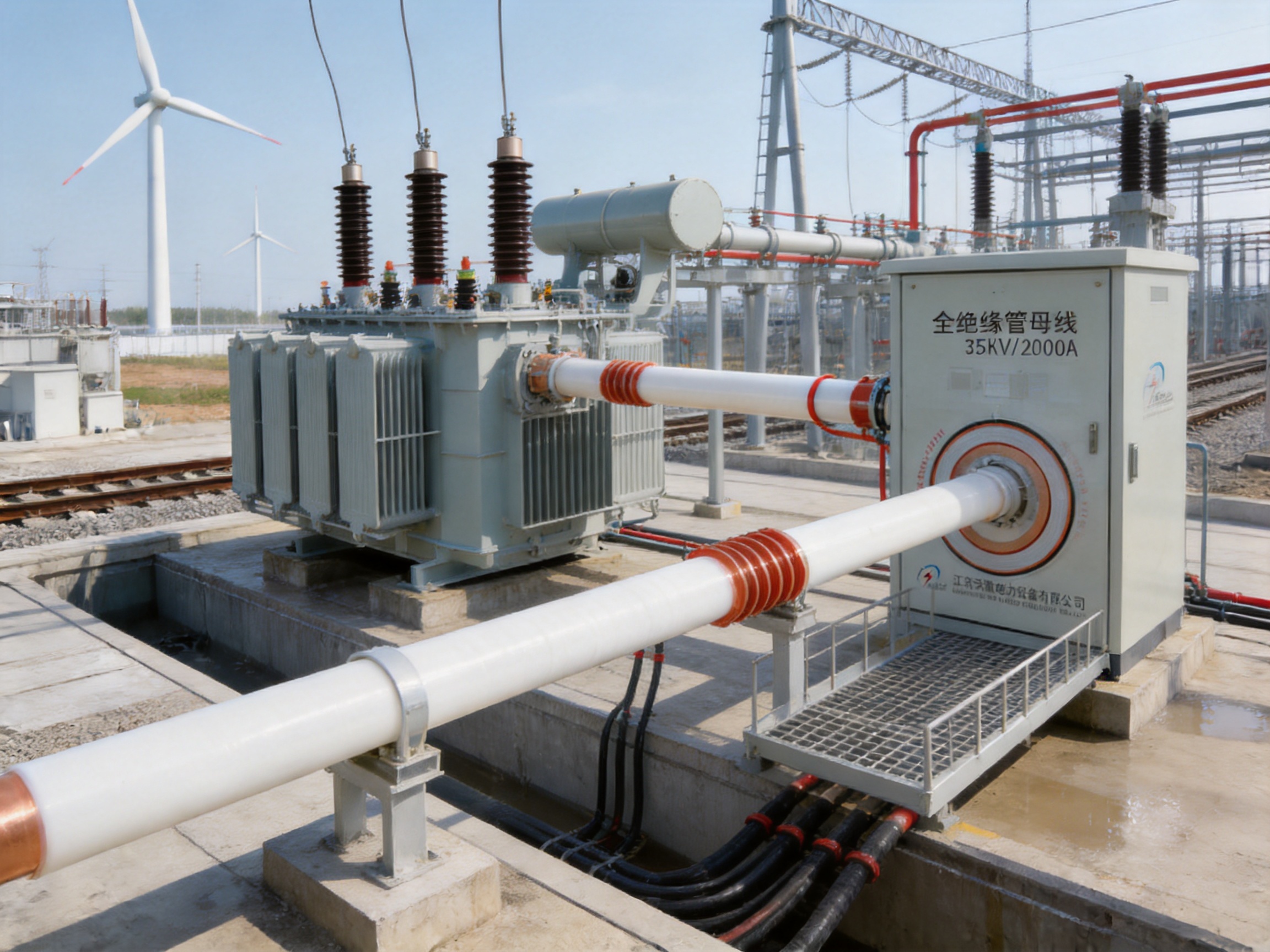
Modern power systems require conductors that can carry substantial current while maintaining reliable insulation, mechanical stability, and long-term resistance to environmental stress. These requirements become especially demanding in substations, industrial facilities, renewable-energy installations, transport infrastructure, and outdoor electrical equipment exposed to moisture, salt spray, chemicals, temperature variation, and contamination. PTFE Tubular Bus Bar technology addresses these challenges by combining a metallic tubular conductor with a carefully engineered polytetrafluoroethylene insulation system.
Unlike conventional bare busbars, cable assemblies, or standard resin-insulated conductors, a PTFE Tubular Bus Bar is designed as an integrated electrical and mechanical system. Its conductor provides a low-impedance current path, while the PTFE insulation, capacitive screens, grounding components, and creepage extenders work together to control electric stress and prevent insulation failure. This structure makes the product suitable for applications where ordinary insulation systems may suffer from thermal aging, chemical attack, moisture ingress, or inadequate creepage distance.
Jiangsu Wopeng Power Technology Co., Ltd. develops and manufactures insulated busbar systems for high-current and critical power applications. Its product range includes epoxy resin vacuum-cast tubular busbars, low-voltage cast-resin busway systems, copper and aluminum tubular busbars, wind-power tubular busbars, compact busbar systems, and sliding contact line systems. Within this portfolio, PTFE Tubular Bus Bar is positioned as a specialized solution for severe operating environments requiring unusually broad temperature tolerance, strong chemical resistance, low dielectric loss, and high enclosure protection.
The design described in this article uses precision mechanical winding of PTFE film. Silicone oil is applied between layers to create a dense, continuous, gas-free insulation structure. The system incorporates at least five capacitive screens, including zero, grading, and grounding screens, to improve electric-field distribution. Silicone-rubber creepage extenders further increase the surface creepage path and help maintain insulation performance in polluted or humid environments. Depending on the final design, the complete assembly can achieve protection levels up to IP68.
1. What Is a PTFE Tubular Bus Bar?
A PTFE Tubular Bus Bar is an insulated busbar assembly consisting primarily of a conductive metal tube or conductor core and a multilayer PTFE insulation system. The conductor may be manufactured from copper or aluminum, depending on the required ampacity, weight, short-circuit withstand capability, installation conditions, and project budget. The insulated assembly is engineered to transmit electrical power safely while reducing the exposure of the energized conductor to people, equipment, moisture, dust, and corrosive contaminants.
PTFE, commonly known as polytetrafluoroethylene, is a fluoropolymer recognized for its very low friction coefficient, chemical inertness, low dielectric loss, non-stick surface, and excellent resistance to thermal degradation. These properties make it different from many conventional polymeric insulation materials. PTFE does not easily react with acids, alkalis, salts, oils, or many organic solvents, and it maintains useful insulating characteristics over a wide temperature range.
For the product configuration supplied by Wopeng, the principal insulation is formed by mechanically winding PTFE film around the conductor. The winding process is not equivalent to simply wrapping tape around a metal tube. It requires controlled tension, accurate overlap, consistent alignment, correct layer sequencing, and careful management of the interlayer medium. Silicone oil is introduced between layers to reduce voids and promote a dense, continuous insulation structure. The resulting design is intended to minimize partial-discharge risks associated with air pockets and irregular interfaces.
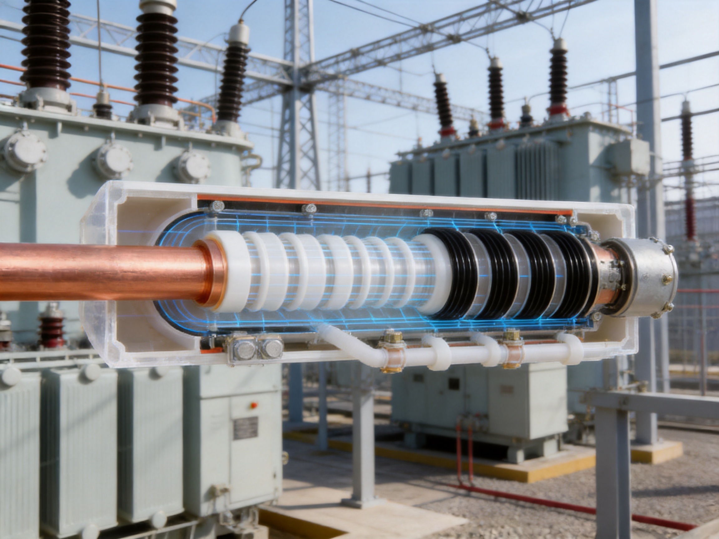
The insulation system also includes capacitive screens. These screens divide the electrical stress across the insulation instead of allowing the entire voltage gradient to concentrate at one interface. A zero screen, grading screen, and grounding screen may be combined with additional semiconductive or conductive layers according to the rated voltage and project requirements. The screens are connected and positioned in a controlled manner so that the electric field remains more uniform along the radial and longitudinal directions of the busbar.
Silicone-rubber creepage extenders are installed where additional surface distance is required. Creepage is the shortest distance along an insulating surface between two conductive parts. In locations affected by condensation, industrial pollution, salt deposits, or dust, surface leakage can become a major concern. Creepage extenders increase the effective leakage path and help maintain insulation reliability under contaminated conditions.
Typical Construction
A typical PTFE Tubular Bus Bar may contain the following elements:
- A copper or aluminum tubular conductor sized for the specified continuous current and short-circuit duty.
- A prepared conductor surface with controlled dimensional accuracy and appropriate electrical interfaces.
- A primary PTFE film insulation system applied by precision mechanical winding.
- Silicone oil or another specified interlayer medium to reduce voids and improve continuity.
- Multiple capacitive screens for electric-field grading and grounding.
- Sealed end structures, terminals, and connection components designed for the project configuration.
- Silicone-rubber creepage extenders where environmental pollution or high voltage requires longer surface distance.
- An external protective arrangement capable of achieving a protection rating up to IP68 when correctly specified and installed.
The exact construction depends on rated voltage, continuous current, conductor material, installation orientation, ambient temperature, altitude, pollution level, short-circuit current, support spacing, and connection method. For this reason, a PTFE Tubular Bus Bar should be selected as an engineered assembly rather than as a generic off-the-shelf tube.
2. Core Electrical and Environmental Performance
The main value of PTFE Tubular Bus Bar technology comes from the interaction between its material properties and its controlled multilayer construction. PTFE alone does not replace sound electrical design, manufacturing discipline, testing, or correct installation. However, when it is processed correctly, it provides a strong insulation platform for demanding power systems.
Wide Operating Temperature Range
The product is designed for an operating temperature range from approximately -60°C to 250°C in the specified extreme-environment configuration. Some project configurations and published design references may use a lower upper operating limit, such as 200°C, depending on the conductor, end fittings, sealing materials, screen arrangement, current loading, and applicable qualification requirements. The final temperature rating must therefore be confirmed against the complete assembly rather than the PTFE film alone.
This broad temperature capability is valuable in outdoor substations, high-temperature industrial areas, furnace-related facilities, power-generation equipment, and cold-climate installations. At low temperatures, brittle or poorly selected insulation materials may lose flexibility or develop cracking under mechanical stress. At high temperatures, some resin and elastomer systems may soften, age, or lose dielectric strength. PTFE offers a greater thermal margin for many of these conditions, although all supporting materials and interfaces must be selected for the same service environment.
Temperature performance also affects current capacity. A conductor can carry more or less current depending on its allowable temperature rise, installation arrangement, heat dissipation, ambient temperature, and proximity to other energized components. A high-temperature insulation material does not automatically mean that the busbar can carry unlimited current. Thermal calculations remain essential for every project.
Corrosion and Chemical Resistance
PTFE is highly resistant to acids, alkalis, salt spray, moisture, and many organic solvents. This characteristic gives the PTFE Tubular Bus Bar an advantage in coastal regions, chemical plants, wastewater facilities, mining operations, industrial processing areas, and locations where airborne contaminants can attack exposed metals or conventional insulation systems.
Corrosion resistance helps protect the electrical interface, but the complete assembly still requires attention to terminals, fasteners, screen connections, support hardware, and sealing components. Wopeng’s engineering process can specify compatible metals, surface treatments, sealing materials, and connection methods according to the surrounding atmosphere. This system-level approach is more reliable than evaluating only the insulation film.
In corrosive environments, the enclosure and installation arrangement are also important. Even an IP68-rated assembly can be compromised by an incorrectly sealed joint, damaged end termination, unsuitable gland, or unprotected connection. Factory-controlled assembly and inspection reduce these risks before the product reaches the installation site.
High Dielectric Strength and Low Dielectric Loss
The PTFE insulation system is designed to provide high dielectric strength and stable insulation resistance. The technical reference data supplied for the product describes a dielectric breakdown strength of at least 35 kV/mm and insulation resistance above 1.0 × 10¹⁴ ohms for the referenced configuration. Dielectric loss is identified as being as low as 0.0002 at 50 Hz under specified test conditions.
These values should be understood as design or reference targets that depend on thickness, manufacturing quality, temperature, test method, frequency, screen configuration, and product dimensions. They should not be treated as universal values for every possible busbar size. Wopeng can provide project-specific technical documentation and test requirements for evaluation by the customer’s engineering team.
Low dielectric loss is especially useful in long power connections and high-voltage installations because it can reduce insulation-related energy loss and heating. A controlled electric field also helps reduce local stress concentrations. The presence of capacitive screens is important because a high-quality polymer alone cannot compensate for poor field grading at joints, terminations, bends, or changes in geometry.
Moisture Protection and IP68 Capability
The product configuration can achieve protection up to IP68. The first digit indicates protection against dust ingress, while the second digit relates to protection against water under defined immersion conditions. IP ratings apply to the tested assembly and installation configuration; they do not mean that every joint, terminal, or field modification automatically retains the same rating.
High enclosure protection is beneficial in underground cable trenches, cable mezzanines, outdoor substations, industrial workshops, marine-influenced locations, and areas subject to washdown or flooding risk. A sealed tubular busbar also reduces the likelihood of accidental contact with energized conductors and limits contamination of the main insulation surface.
To preserve the intended protection level, installation procedures must include correct joint preparation, torque control, sealing inspection, and protection of the end fittings. Wopeng’s factory assembly and inspection processes are intended to provide a repeatable baseline before delivery.
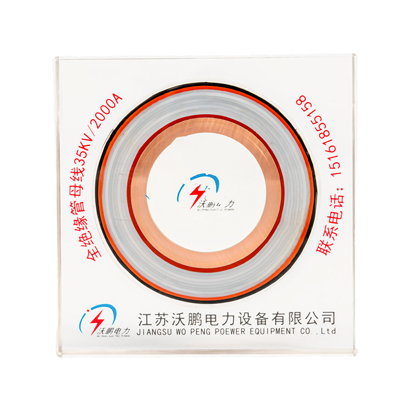
PTFE Tubular Bus Bar
3. Electric-Field Control Through Capacitive Screens
One of the most important differences between a basic insulated conductor and an engineered high-voltage tubular busbar is the control of electric-field distribution. When voltage is applied to a conductor surrounded by insulation, the electric field is not always uniform. It may become concentrated around sharp edges, changes in diameter, connection points, or poorly controlled interfaces. Local concentration can increase partial discharge and accelerate insulation aging.
The PTFE Tubular Bus Bar uses multiple capacitive screens to manage this condition. The screens are arranged at carefully determined positions within the insulation system. The zero screen establishes a controlled reference condition, grading screens divide voltage stress between layers, and the grounding screen provides a defined protective and electrical reference. Additional screens may be included to suit the rated voltage and insulation geometry.
Capacitive grading works by controlling the capacitance distribution across the insulation. Rather than allowing one region to absorb a disproportionate share of the voltage, the screen system creates a more predictable potential gradient. This is particularly important at high-voltage terminations and transitions, where field distortion is often most severe.
Screen continuity is a critical manufacturing requirement. A screen that is discontinuous, incorrectly overlapped, damaged during winding, or improperly connected may not perform as intended. For this reason, screen placement, overlap, connection, and insulation between layers must be verified as part of production control. The design should also include suitable grounding arrangements so that accessible conductive components remain at a safe potential.
Partial-Discharge Considerations
Partial discharge is a localized electrical discharge that does not completely bridge the insulation between conductors. It can occur in voids, defects, contaminated interfaces, or regions of elevated electric stress. Over time, repeated partial discharge may erode insulation and lead to breakdown.
The precision winding process and silicone-oil interlayer treatment are intended to reduce the formation of air pockets. Interlayer tension is controlled to maintain a consistent structure, with the technical information identifying a target uniformity within approximately ±2%. Ultrasonic assistance may be used to help detect or control bubbles during processing. These measures are particularly valuable because even small gas-filled voids can experience higher electrical stress than the surrounding solid insulation.
Partial-discharge testing, where required by the project specification, provides an additional method of verifying insulation quality. Test voltage, acceptance criteria, background-noise level, measurement sensitivity, and environmental conditions should be agreed before production. The final acceptance procedure may include routine and type testing, depending on the voltage class and customer requirements.
4. Manufacturing Process and Quality Control
The performance of a PTFE Tubular Bus Bar depends heavily on manufacturing process control. PTFE has a low surface energy, which contributes to its excellent chemical resistance but makes adhesion and bonding more difficult than with some other insulation materials. The product therefore requires specialized winding, surface treatment, dimensional control, and inspection methods.
Conductor Preparation
Manufacturing begins with the selection and preparation of the conductor. Copper is often chosen where maximum conductivity and compact dimensions are important. Aluminum can reduce weight and material cost while providing an attractive solution for large cross-sections and applications where mechanical support is carefully designed.
The conductor is inspected for dimensional accuracy, straightness, surface condition, and cleanliness. Burrs, sharp edges, oxidation, and contamination can damage the PTFE film or create local electric-field stress. The conductor ends are prepared to accept terminals, joints, or connection hardware. Where required, machining and surface treatment are carried out using controlled equipment.
Wopeng operates production lines supported by CNC machining equipment, automated assembly technologies, and standardized inspection procedures. CNC processing helps maintain repeatability for conductor interfaces, end fittings, drilling patterns, support points, and other project-specific features. This is especially important when multiple busbar sections must be joined on site with precise alignment.
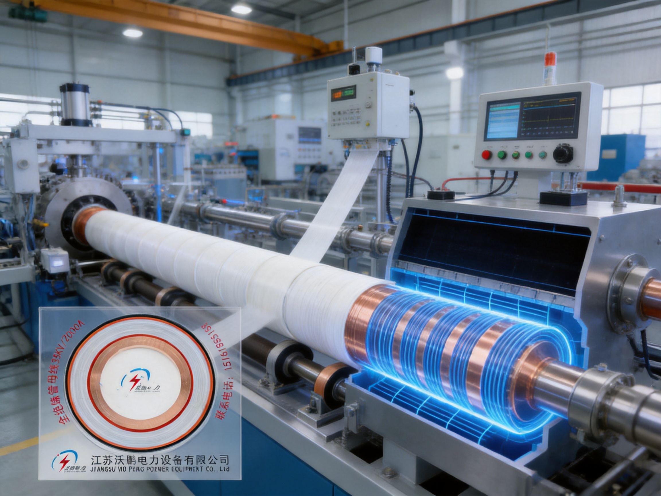
PTFE Film Winding
The PTFE film is applied through a controlled mechanical winding process. Film tension must remain stable throughout the operation. Excessive tension can deform the film, reduce the intended insulation thickness, or introduce mechanical stress. Insufficient tension can produce wrinkles, loose layers, or voids. The overlap ratio must also remain consistent to avoid weak points in the insulation.
The winding equipment is adjusted according to conductor diameter, film width, layer sequence, insulation thickness, and required overlap. Production operators and process engineers monitor alignment, tension, speed, and layer condition. Any variation can affect dielectric strength, flexibility, dimensional accuracy, and the performance of the capacitive screens.
For critical projects, process records can be maintained for each section. These records may include material batch information, winding parameters, inspection results, screen continuity checks, and final test data. Traceability supports quality assurance and helps the manufacturer investigate any future service issue.
Interlayer Treatment and Bubble Control
Because PTFE has a low surface energy, adjacent layers may not naturally bond strongly. Special treatment agents or controlled interlayer methods can be used to improve contact and prevent separation. Silicone oil between layers helps create a dense, gas-free continuous insulation structure, but the quantity, distribution, and compatibility of the medium must be controlled.
Bubble control is a major technical challenge. Trapped air can reduce dielectric reliability and create partial-discharge sites. Wopeng’s process information identifies ultrasonic assistance as a method that may be used to help control bubbles. The effectiveness of this method depends on equipment calibration, process speed, material condition, and operator control.
After winding, the insulation is examined for wrinkles, gaps, foreign particles, thickness variation, surface damage, and dimensional irregularities. Non-destructive inspection methods may be combined with electrical tests to verify the integrity of the completed structure.
Screen Installation and Termination Assembly
Capacitive screens are installed in their specified sequence and connected to the appropriate reference or grounding points. Screen overlaps must be electrically continuous and mechanically secure. The screen system must also be isolated from adjacent layers where required by the design.
Terminations are assembled with particular attention to stress control. The end of a high-voltage insulation system is a critical location because the electric field can spread outward and concentrate at the termination. Grading components, stress cones, screens, sealing interfaces, and creepage extenders are assembled according to controlled drawings and work instructions.
Silicone-rubber creepage extenders are fitted where the application requires additional surface distance. Their geometry, flexibility, weather resistance, and interface with the main insulation are checked before shipment. The end design may be adapted for switchgear connections, transformer terminals, cable-trench routing, or other installation arrangements.
Testing and Inspection
Quality control for a PTFE Tubular Bus Bar may include material inspection, dimensional verification, insulation resistance testing, high-voltage withstand testing, partial-discharge testing, mechanical inspection, screen continuity verification, sealing checks, and routine visual examination. The exact test plan depends on the product design and customer specification.
Wopeng reports standardized inspection processes that include high-voltage tests, insulation tests, mechanical verification, and routine quality checks. Collaboration with third-party testing institutions can provide independent validation for safety and performance. Such cooperation is useful when projects involve utility companies, international customers, EPC contractors, or formal qualification procedures.
A reliable quality system does more than test the finished product. It controls incoming materials, production conditions, equipment calibration, operator training, process documentation, nonconforming-product handling, and corrective action. This approach reduces variation and provides greater confidence that each manufactured section will perform consistently in service.
5. Advantages Compared with Other Insulated Busbar Types
PTFE Tubular Bus Bar is not intended to replace every other busbar technology. Epoxy-resin cast busbars, silicone-rubber insulated busbars, cable systems, and bare tubular conductors each have suitable applications. The main advantage of PTFE is its combination of thermal, chemical, dielectric, and low-friction properties in one insulation system.
| Busbar Type | Reference Breakdown Strength | Reference Temperature Range | Reference Dielectric Loss | Typical Strength |
|---|---|---|---|---|
| PTFE Tubular Bus Bar | At least 35 kV/mm | -60°C to 200°C or up to 250°C in specified configurations | Up to approximately 0.0002 | Extreme temperature and chemical resistance |
| Epoxy Resin Cast Busbar | At least 30 kV/mm | Approximately -30°C to 130°C | Up to approximately 0.001 | Rigid structure and mature cast-insulation technology |
| Silicone Rubber Insulated Busbar | At least 25 kV/mm | Approximately -40°C to 120°C | Up to approximately 0.0005 | Flexibility and weather resistance |
| Bare Tubular Busbar | Dependent on air clearance | Dependent on conductor and environment | Not applicable as an insulated system | Simple construction and low initial material cost |
The values in this table are comparative reference values rather than universal guarantees. Actual performance depends on dimensions, test standards, conductor material, insulation thickness, installation conditions, and the complete product configuration.
Compared with Epoxy Resin Cast Busbars
Epoxy resin cast busbars provide a rigid, compact, and mechanically stable solution. They are widely used in medium-voltage systems and can be manufactured with excellent dimensional control. However, epoxy systems may have a narrower temperature range and can be more sensitive to thermal cycling, impact, or cracking if the design and curing process are not carefully controlled.
PTFE offers a wider temperature capability and stronger resistance to many chemicals and solvents. Its low dielectric loss can also be advantageous in certain high-voltage or long-distance connections. On the other hand, PTFE winding requires specialized process control and may carry a higher material and manufacturing cost. The appropriate choice depends on the balance between environmental severity, voltage level, mechanical requirements, and project economics.
Compared with Silicone-Rubber Insulated Busbars
Silicone rubber provides flexibility, good weather resistance, and strong performance in many outdoor applications. It can be useful where movement, vibration, or installation flexibility is important. PTFE generally provides superior chemical resistance, a lower friction coefficient, and a broader high-temperature capability. The PTFE system may therefore be preferred in chemical, high-temperature, or highly contaminated environments.
Silicone rubber may remain attractive where flexibility, ease of installation, or lower initial cost is more important. The use of silicone-rubber creepage extenders within the PTFE Tubular Bus Bar combines some of the environmental and creepage advantages of silicone rubber with the primary insulation performance of PTFE.
Compared with Cables
Power cables are highly versatile and can be routed over long distances, around obstacles, and through complex infrastructure. They are often suitable for buried or flexible connections. A tubular busbar, however, can provide a clearer and more compact connection between transformers, switchgear, generators, and distribution equipment. It can also be easier to inspect visually and may offer lower impedance for high-current applications when properly designed.
Busbars are especially useful where large currents, short connection distances, controlled routing, and clearly defined termination points are involved. Cables may be preferable where flexibility, long-distance routing, or multiple directional changes are necessary. The selection should consider current rating, fault level, electromagnetic forces, installation space, maintenance, fire requirements, and total project cost.
Compared with Bare Busbars
Bare busbars may have a lower initial material cost and simple construction, but they require larger air clearances and more extensive protection against accidental contact, contamination, animals, and moisture. Their installation can require additional barriers, insulators, support frames, and maintenance procedures.
A fully insulated tubular busbar reduces exposed energized surfaces and can simplify routing through cable trenches, mezzanines, and enclosed electrical rooms. Its sealed design also reduces contamination-related maintenance. The increased manufacturing cost is often justified where safety, compactness, environmental protection, and long-term reliability are high priorities.
6. Application Solutions for PTFE and Insulated Tubular Busbars
Transformer-to-Switchgear Connections
One of the most common applications is the connection between the low-voltage or medium-voltage terminals of a main transformer and the switchgear or control-room cabinet. This arrangement can provide a direct, organized, and visually clean power path. The tubular busbar is engineered to match the transformer terminal arrangement, switchgear interface, phase spacing, support system, and required current rating.
For high-current transformer connections, a tubular busbar may reduce the number of parallel cables and associated cable-support requirements. It can also simplify phase identification and improve the organization of the electrical room. The final design must account for transformer vibration, thermal expansion, short-circuit forces, and the movement permitted by the connection interface.
Routing Through Cable Trenches
Insulated tubular busbars can be routed through underground cable trenches or dedicated cable channels. This method is suitable where the connection must pass below floors, between buildings, or through areas where overhead routing is undesirable. A fully insulated construction provides additional protection in locations that may experience humidity, dust, standing water, or accidental contact.
Drainage, support spacing, joint accessibility, and thermal ventilation should be addressed during design. Although the busbar can be sealed, the trench itself should not be treated as a substitute for correct product protection. The installation must provide adequate mechanical support and prevent excessive bending or impact during construction.
Cable Mezzanine and Switchgear Interconnections
A cable mezzanine provides a useful route between switchgear lineups, transformers, generators, and auxiliary electrical equipment. Tubular busbars can be arranged in a clear phase sequence and supported along the mezzanine structure. This can reduce congestion compared with large groups of parallel power cables.
Where a project contains several switchgear sections, prefabricated busbar sections can be manufactured to defined lengths and connection coordinates. This improves installation accuracy and can reduce field cutting, drilling, and termination work. Factory-made sections also allow more extensive testing before delivery.
Renewable-Energy and Wind-Power Systems
Wind-power equipment and other renewable-energy installations often experience vibration, temperature cycling, moisture, ultraviolet exposure, and difficult maintenance conditions. Tubular busbar systems can be designed for generator connections, transformer interfaces, tower sections, or collector systems. PTFE is particularly attractive where the installation combines temperature variation with chemical or moisture exposure.
Wind-turbine applications require special consideration of vibration, movement, lightning protection, grounding, and electromagnetic compatibility. The busbar system must be coordinated with the turbine’s converter, transformer, generator, and protection equipment. Wopeng’s broader product portfolio includes tubular busbars for wind-power applications, allowing the engineering process to consider the complete electrical system rather than an isolated conductor.
Industrial and Transport Infrastructure
Industrial plants, rail-transit facilities, large commercial buildings, and power-generation sites often require high-current connections in confined or environmentally challenging areas. A compact insulated tubular busbar can be used where safety clearances, reliable enclosure, and organized routing are important.
In rail and transport infrastructure, equipment may be exposed to vibration, dust, moisture, and limited access for maintenance. In industrial facilities, the atmosphere may include oils, solvents, acids, alkalis, or conductive dust. PTFE’s resistance to many of these contaminants can provide an advantage, provided that the complete assembly and external hardware are designed for the same conditions.
7. Custom Engineering and Product Configuration
There is no single PTFE Tubular Bus Bar dimension suitable for every installation. A professional manufacturer begins with the electrical and mechanical design conditions. Important input data includes rated voltage, rated current, frequency, short-circuit current, duration of fault, conductor material, conductor cross-section, insulation thickness, screen arrangement, ambient temperature, altitude, pollution severity, protection rating, terminal geometry, support spacing, and required service life.
Wopeng provides custom and OEM manufacturing support for customers requiring specific conductor sizes, insulation thicknesses, busbar lengths, terminal arrangements, bends, screen connections, and installation interfaces. Customization can also include the design of transformer connections, switchgear interfaces, flexible sections, expansion provisions, grounding points, and monitoring components.
Conductor Selection
Copper provides high electrical conductivity and strong mechanical performance in a relatively compact cross-section. It can be useful where installation space is limited or where a high current must be transmitted with controlled temperature rise. Aluminum offers lower weight and may be preferred for large conductors or applications where transportation and support loads must be minimized.
The choice between copper and aluminum should include conductivity, thermal expansion, joint design, surface treatment, galvanic compatibility, mechanical strength, and total material cost. Correct contact pressure and joint preparation are essential for either material.
Insulation Thickness and Voltage Class
The technical reference for the product identifies a typical PTFE insulation thickness of approximately 4 to 8 mm. Actual thickness depends on voltage, electric-field requirements, mechanical dimensions, screen structure, test voltage, and the required safety margin. Higher voltage does not simply require a thicker layer; it also requires correct grading, termination design, creepage distance, and control of defects.
Some reference materials describe applications ranging from 110 kV to 500 kV, while Wopeng’s general product portfolio is stated to cover systems from low voltage to 35 kV. These figures represent different product or design contexts and should not be combined without project verification. Customers should request a product-specific rating, test report, and application confirmation for the intended voltage level. The final design must comply with the relevant national and international standards.
Mechanical Design
Although PTFE has excellent low-friction properties, the complete busbar assembly must withstand transportation, installation, vibration, thermal expansion, electromagnetic forces, and short-circuit stress. Supports should be positioned according to calculated loads rather than convenience. Bends and connection points require particular attention because mechanical stress can affect insulation interfaces and screen continuity.
Low friction can reduce mechanical stress between sliding interfaces and help accommodate controlled movement. Nevertheless, PTFE’s dimensional behavior, creep characteristics, and interaction with metal supports must be considered. The use of suitable clamps, spacers, expansion provisions, and termination supports is necessary for a dependable installation.
8. Intelligent Monitoring and Condition Management
For critical power systems, inspection at the time of installation may not be sufficient. Continuous or periodic monitoring can provide information about operating conditions and support preventive maintenance. Wopeng has developed a tubular busbar monitoring system intended to support unmanned intelligent monitoring of multiple technical parameters.
Depending on the project, monitoring may involve temperature, leakage-related conditions, grounding status, insulation behavior, environmental humidity, or other operating indicators. The exact sensor arrangement and communication method should be selected according to the customer’s control system and maintenance strategy.
Condition monitoring is particularly useful in remote substations, renewable-energy sites, industrial plants with limited access, and facilities where an unexpected outage would have a high economic impact. Data can help maintenance personnel identify abnormal temperature rise, changes in operating conditions, or developing problems before they cause a major failure.
Monitoring does not replace correct insulation design or routine testing. It complements those measures by providing additional information during service. A complete condition-management plan should define alarm thresholds, data-storage requirements, communication protocols, inspection intervals, and response procedures.
9. Installation, Commissioning, and Maintenance
Proper installation is essential to achieve the performance demonstrated during factory testing. Before installation, the busbar sections should be inspected for shipping damage, contamination, moisture, deformation, and missing accessories. Protective packaging should remain in place until the product is ready to be installed in a clean and controlled area.
Connection surfaces must be clean and free from inappropriate grease, dust, metal particles, and oxidation. Bolted joints should be tightened according to the specified torque. Incorrect torque can create excessive contact resistance, damage the interface, or reduce mechanical stability. Phase identification and grounding connections must be verified before energization.
The installation team should confirm alignment between the busbar and connected equipment. Forced alignment can place stress on terminals, screens, supports, or insulation. Expansion provisions should be installed where temperature changes or equipment movement may cause displacement. The minimum bending radius and support spacing specified by the manufacturer should not be exceeded.
Commissioning may include insulation resistance measurement, high-voltage withstand testing, phase verification, continuity checks, grounding verification, visual inspection, and functional testing of monitoring equipment. Test voltage and duration must be selected carefully so that the commissioning procedure is compatible with the insulation system and connected equipment.
During service, maintenance requirements are generally reduced compared with exposed bare conductors because the insulated structure limits contamination and accidental contact. However, periodic inspection remains necessary. Personnel should examine accessible joints, support brackets, seals, termination areas, grounding connections, monitoring devices, and signs of mechanical movement or overheating.
In environments with heavy pollution, condensation, or vibration, inspection intervals may need to be shortened. Any visible cracking, swelling, discoloration, unusual odor, damaged creepage extender, loose support, or abnormal temperature should be investigated before the system is returned to full service.
10. Company Manufacturing Strengths
Jiangsu Wopeng Power Technology Co., Ltd. was founded in 2018 as a specialized high-tech enterprise focused on high- and low-voltage busbar systems. The company combines product development, engineering design, manufacturing, testing, and application support. This integrated capability is valuable for projects in which the busbar must be adapted to transformer terminals, switchgear layouts, cable routes, support structures, and monitoring systems.
The company’s product portfolio covers 35 kV epoxy resin vacuum-cast tubular busbars, low-voltage epoxy-cast busbar trunking, copper and aluminum tubular busbars, wind-power tubular busbars, compact busbar systems, and sliding contact line power supply systems. This range demonstrates experience with multiple insulation technologies, conductor materials, current levels, and installation environments.
Wopeng operates modern production lines equipped with vacuum casting systems, CNC machining equipment, and automated assembly technologies. Vacuum casting is important for producing resin-insulated busbar products with reduced void content and controlled insulation quality. CNC machining improves the accuracy of conductor interfaces and customized metal components. Automated assembly supports consistent positioning and repeatability, especially when multiple units must be produced to the same project drawings.
The company employs experienced engineers, technical specialists, and production professionals with knowledge of power equipment technology. Engineering personnel can participate in conductor selection, electric-field analysis, mechanical design, thermal evaluation, connection design, and product customization. This helps customers move from a general requirement to a manufacturable and testable busbar system.
Quality management includes high-voltage tests, insulation tests, mechanical verification, and routine inspections. Third-party testing cooperation provides additional independent evaluation when required. The company reports that its products operate across more than 17 provinces and key industrial sectors, including power generation, substations, wind energy, industrial manufacturing, rail transit, and large commercial facilities.
A manufacturer’s strength should be measured not only by the materials it purchases but also by its ability to control the complete production chain. For PTFE Tubular Bus Bar, this includes film handling, winding tension, interlayer treatment, screen installation, termination assembly, sealing, dimensional inspection, electrical testing, documentation, and technical support. Wopeng’s engineering and manufacturing structure is intended to address these requirements as one coordinated process.
11. Technical Challenges and How They Are Managed
Winding Tension Uniformity
Uniform winding tension is one of the most demanding production requirements. The technical information identifies an interlayer tension uniformity target within approximately ±2%. Maintaining this range requires stable equipment, accurate sensors, controlled film quality, and trained operators. Variations can result in uneven insulation thickness, wrinkles, excessive compression, or voids.
Process parameters should be monitored during production rather than checked only after completion. If a deviation is detected early, the affected section can be corrected before additional layers are applied. This reduces material waste and improves the consistency of the final product.
Low Surface Energy and Interlayer Adhesion
PTFE’s low surface energy is a performance advantage in chemical resistance and low friction, but it makes interlayer adhesion difficult. If layers are not properly treated or compressed, separation may occur during thermal cycling or mechanical handling. Special treatment agents, controlled interlayer media, suitable winding pressure, and process verification are therefore necessary.
The purpose of the interlayer structure is not necessarily to create a conventional adhesive bond between every PTFE surface. It is to form a stable, dense, continuous insulation system with controlled interfaces and minimal voids. The production method must be validated for the specific film, thickness, temperature range, and mechanical requirements.
Material Cost
PTFE is more expensive than many common insulation materials. The film, special treatment, precision winding equipment, screen system, and inspection requirements can make PTFE Tubular Bus Bar more costly than standard resin-cast or rubber-insulated alternatives.
However, initial purchase price is only one part of total ownership cost. A product that withstands severe temperature, chemical exposure, moisture, and contamination may reduce replacement frequency, outage risk, cleaning requirements, and maintenance labor. A lifecycle comparison should include installation, inspection, environmental protection, downtime, energy loss, and expected service life.
Recycling and Environmental Processing
PTFE is difficult to degrade and requires specialized environmental processing at the end of its service life. This is a genuine consideration for customers with strict sustainability policies. Product life extension, repairability, material documentation, controlled dismantling, and cooperation with qualified waste-processing organizations can help address this issue.
At the same time, long service life and reduced maintenance can offset some environmental impacts during operation. Customers should evaluate the complete lifecycle, including material sourcing, manufacturing energy, transport, operating losses, maintenance, and end-of-life treatment.
12. Selecting a Reliable PTFE Tubular Bus Bar Manufacturer
Purchasers should evaluate more than a product brochure when selecting a PTFE Tubular Bus Bar supplier. The manufacturer should be able to explain the insulation structure, conductor material, screen arrangement, winding process, testing program, terminal design, protection rating, and installation requirements.
Important evaluation questions include:
- Can the supplier provide product-specific electrical and mechanical drawings?
- Are the insulation thickness, conductor size, and screen configuration clearly defined?
- Can the supplier provide insulation, high-voltage, partial-discharge, and mechanical test documentation where required?
- Does the factory have suitable winding, machining, assembly, and inspection equipment?
- Are process records and material traceability available?
- Can the product be customized for transformer, switchgear, trench, mezzanine, or renewable-energy applications?
- Does the supplier provide installation instructions, joint procedures, and commissioning support?
- Can the manufacturer explain the applicable operating temperature and protection rating for the complete assembly?
- Are third-party tests or independent validations available for the intended application?
A professional supplier should also identify limitations rather than presenting every application as universally suitable. The rated voltage, current, temperature, IP level, and service life must be connected to a defined design and test condition. Clear technical communication reduces the risk of selecting a product based on isolated material properties.
13. Frequently Asked Questions
Q1: What is the main purpose of a PTFE Tubular Bus Bar?
A PTFE Tubular Bus Bar provides a compact, insulated, and high-current power connection using a metal tubular conductor surrounded by a multilayer PTFE insulation system. It is intended for applications requiring strong environmental resistance, controlled electric fields, and reliable insulation in demanding conditions.
Q2: What conductor materials are available?
Copper and aluminum conductors can be considered. Copper offers high conductivity and compact dimensions, while aluminum can reduce weight and material cost for large conductor sizes. The correct choice depends on current, temperature rise, mechanical loading, joint design, and project economics.
Q3: What temperature range can the product withstand?
The extreme-environment configuration is described as operating from approximately -60°C to 250°C. Other configurations may have a lower upper limit, such as 200°C, because the final rating depends on terminals, seals, screens, conductor loading, and the complete assembly. The supplier should confirm the rating for the exact project model.
Q4: Is PTFE Tubular Bus Bar resistant to chemicals?
PTFE is resistant to many acids, alkalis, salts, moisture, and organic solvents. This makes it suitable for many corrosive or polluted environments. Nevertheless, terminals, fasteners, seals, supports, and external accessories must also be selected for compatibility with the site atmosphere.
Q5: What is the purpose of the capacitive screens?
Capacitive screens control the distribution of electric stress across the insulation. They help reduce field concentration at interfaces and terminations. The system may include zero, grading, and grounding screens, with the exact arrangement determined by voltage level and product geometry.
Q6: Can the busbar achieve IP68 protection?
The specified product configuration can achieve protection up to IP68. The rating applies to the tested assembly and depends on correct sealing, joint construction, end termination, and installation. Field modifications or improperly sealed connections may reduce the achieved protection level.
Q7: Is the product suitable for every high-voltage system?
No. Suitability depends on rated voltage, current, fault level, insulation coordination, installation conditions, applicable standards, and the complete electrical design. Some reference material describes high-voltage applications up to 110 kV–500 kV, while the company’s general product portfolio covers systems up to 35 kV. Customers should obtain project-specific confirmation before ordering.
Q8: How does PTFE compare with epoxy resin insulation?
PTFE generally provides a broader temperature range, stronger chemical resistance, lower friction, and very low dielectric loss. Epoxy resin cast busbars can offer excellent rigidity, dimensional stability, and mature medium-voltage manufacturing. The best selection depends on environmental conditions, mechanical requirements, voltage, and cost.
Q9: Can special sizes and connection arrangements be manufactured?
Yes. A custom manufacturer can produce specific conductor dimensions, insulation thicknesses, lengths, terminal designs, bends, screen arrangements, support points, and monitoring interfaces. Accurate project drawings and installation data are required before engineering approval.
Q10: What tests should be requested before shipment?
Depending on the project, customers may request dimensional inspection, insulation resistance testing, high-voltage withstand testing, partial-discharge testing, screen continuity testing, mechanical verification, sealing inspection, and routine visual examination. The complete test plan should be agreed during technical clarification.
Q11: What service life can be expected?
The reference information indicates a potential service life of approximately 35 to 45 years under normal high-voltage working conditions. Actual service life depends on temperature, current loading, thermal cycling, mechanical vibration, pollution, installation quality, maintenance, and compliance with the specified operating limits.
Q12: Does Wopeng provide OEM support?
Jiangsu Wopeng Power Technology provides custom and OEM busbar solutions. Its engineering team can support product selection, conductor configuration, insulation design, terminal adaptation, manufacturing, testing, and application coordination for project-specific requirements.
14. Conclusion
PTFE Tubular Bus Bar technology provides a specialized answer to the challenges of high-current power transmission in extreme environments. Its value is based on more than the use of PTFE as an insulation material. Precision mechanical winding, controlled interlayer treatment, bubble reduction, multiple capacitive screens, silicone-rubber creepage extenders, sealed construction, and systematic testing work together to create a reliable insulated busbar assembly.
Compared with conventional epoxy, silicone-rubber, cable, or bare-busbar solutions, PTFE can offer a stronger combination of temperature resistance, chemical resistance, low dielectric loss, low friction, and moisture protection. The technology is especially attractive for corrosive industrial sites, outdoor substations, renewable-energy facilities, cable trenches, switchgear connections, and other locations where maintenance access is limited or environmental conditions are severe.
The product does require specialized manufacturing and may have a higher initial cost. PTFE’s low surface energy creates challenges in interlayer adhesion, its material is difficult to recycle, and the complete system must be carefully engineered for thermal, electrical, and mechanical performance. These factors make supplier capability particularly important.
Jiangsu Wopeng Power Technology combines engineering experience, CNC machining, vacuum casting capability, automated assembly, high-voltage testing, insulation testing, mechanical verification, and customized OEM production. This manufacturing foundation enables the company to develop busbar systems adapted to the actual requirements of transformers, switchgear, substations, wind-power equipment, industrial plants, rail transit, and large commercial facilities.
For customers seeking a long-life insulated conductor for demanding service, the correct approach is to evaluate the complete design, not only the material name. With accurate technical data, project-specific testing, correct installation, and appropriate monitoring, a PTFE Tubular Bus Bar can provide a dependable and efficient component within a modern power-distribution system.
References
1. IEC 60137, Insulated Bushings for Alternating Voltages above 1,000 V.
2. IEC 60840, Power Cables with Extruded Insulation and Their Accessories for Rated Voltages above 30 kV up to 150 kV.
3. IEC 62271 Series, High-Voltage Switchgear and Controlgear.
4. IEC 60529, Degrees of Protection Provided by Enclosures.
5. IEC 60071 Series, Insulation Coordination.
6. ASTM D149, Standard Test Method for Dielectric Breakdown Voltage and Dielectric Strength of Solid Electrical Insulating Materials at Commercial Power Frequencies.
7. ASTM D257, Standard Test Methods for DC Resistance or Conductance of Insulating Materials.
8. Technical product information for PTFE Tubular Bus Bar systems, including insulation construction, temperature performance, screen configuration, and application requirements.
9. Technical manufacturing information concerning PTFE film winding, interlayer treatment, bubble control, CNC machining, automated assembly, and electrical inspection.
10. Manufacturer engineering data for custom insulated busbar systems, tubular busbars, cast-resin busways, and related power-transmission equipment.
Product: PTFE Tubular Bus Bar




-
 +86-180 3625 3000
-
 admin@wpbusbar.com
-
 No. 8, Yanjin Road, Chengxi Industrial Park, Shanyang Town, Baoying County, Yangzhou City, Jiangsu Province, China
Copyright © Jiangsu Wopeng Power Technology Co., Ltd.
All Rights Reserved.
 Custom Insulated Bus Bar Manufacturer
Tubular Busbar System Factory
Custom Insulated Bus Bar Manufacturer
Tubular Busbar System Factory