

 EN
EN

 English
 русский
 Français
 Español
 عربى
عربى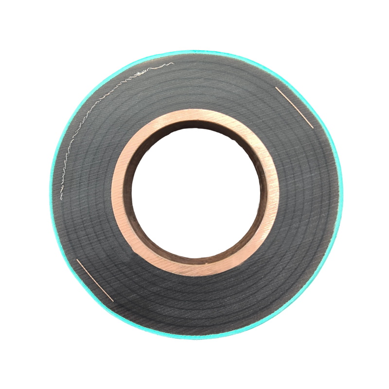
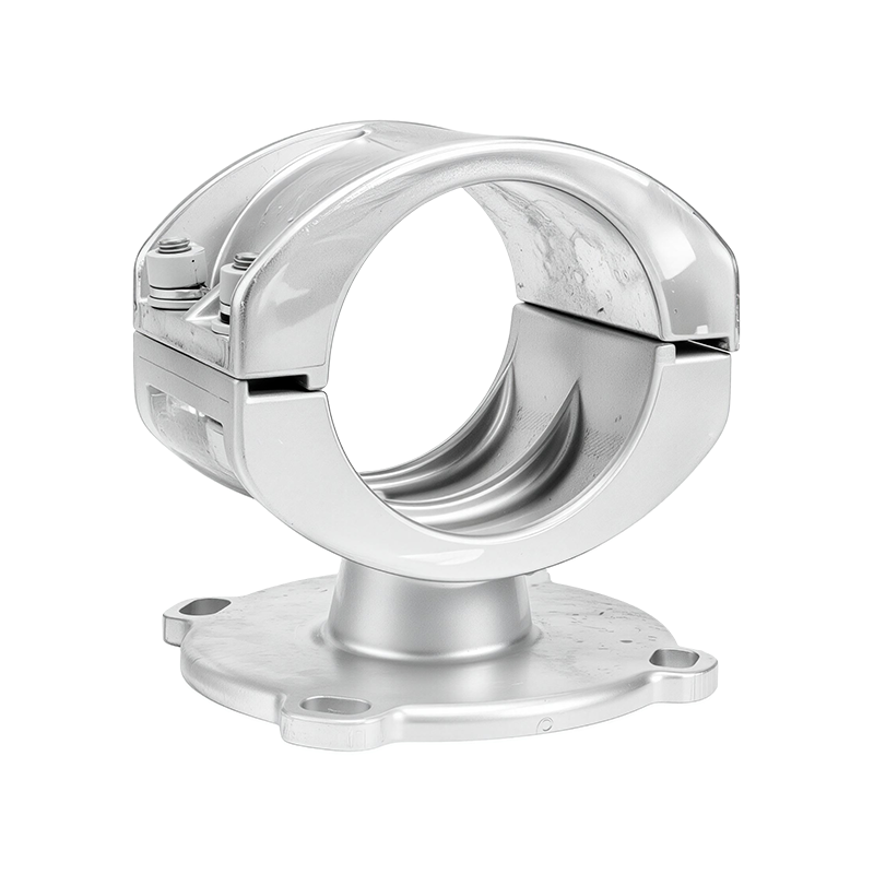
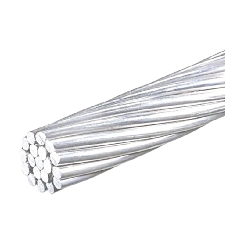
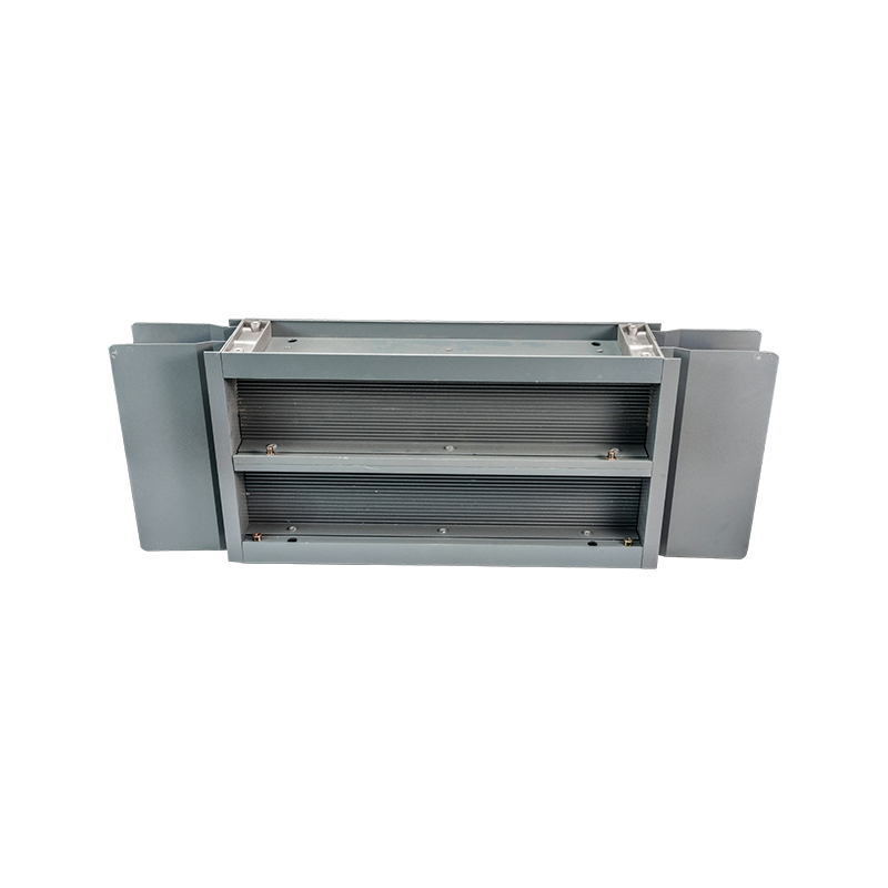
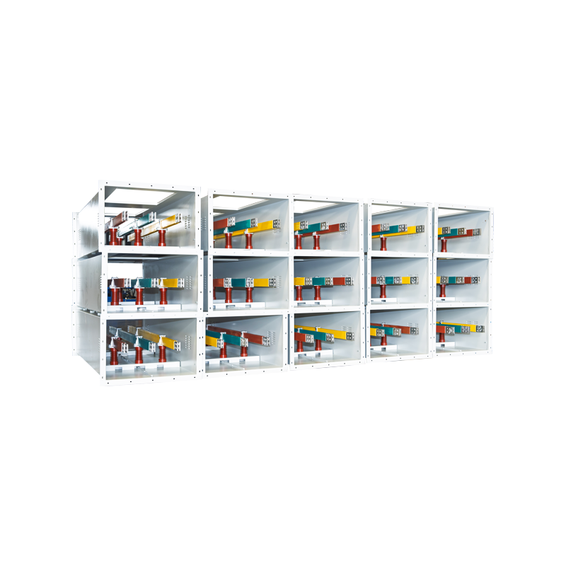
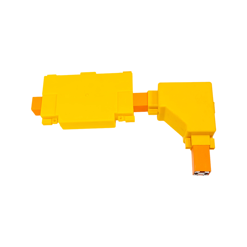

PTFE Tubular Bus Bar: Advanced Insulation for Extreme-Environment Power Systems
Content
- 1 1. What Is a PTFE Tubular Bus Bar?
- 2 2. Why PTFE Is Suitable for Extreme Environments
- 3 3. Electrical Performance and Field Control
- 4 4. Performance Advantages Over Conventional Insulated Busbars
- 5 5. Advanced Manufacturing Process
- 5.1 5.1 Engineering and Design Review
- 5.2 5.2 Conductor Preparation
- 5.3 5.3 PTFE Film Preparation
- 5.4 5.4 Precision Mechanical Winding
- 5.5 5.5 Bubble and Void Control
- 5.6 5.6 Inter-Layer Adhesion Treatment
- 5.7 5.7 Silicone Oil Application
- 5.8 5.8 Installation of Creepage Extenders
- 5.9 5.9 End Terminations and Sealing
- 5.10 5.10 CNC Machining and Automated Assembly
- 6 6. Quality Assurance and Testing
- 7 7. Applications of PTFE Tubular Bus Bar
- 7.1 7.1 Outdoor Substations
- 7.2 7.2 Chemical and Process Industries
- 7.3 7.3 Coastal and Marine Infrastructure
- 7.4 7.4 High-Temperature Industrial Areas
- 7.5 7.5 Renewable Energy and Wind Power
- 7.6 7.6 Rail Transit and Large Facilities
- 7.7 7.7 Transformer-to-Switchgear Connections
- 7.8 7.8 Cable Trenches and Cable Mezzanines
- 8 8. Installation and System Design Considerations
- 9 9. Customization Capabilities
- 10 10. Manufacturing Strengths of Jiangsu Wopeng Power Technology
- 11 11. Maintenance and Service Life
- 12 12. Economic Evaluation
- 13 13. How to Select the Right Product
- 14 14. Frequently Asked Questions
- 14.1 Q1: What is the main advantage of PTFE Tubular Bus Bar?
- 14.2 Q2: What voltage levels are suitable for this product?
- 14.3 Q3: Can the product operate at 250°C?
- 14.4 Q4: Why are capacitive screens needed?
- 14.5 Q5: What is the function of silicone oil between PTFE layers?
- 14.6 Q6: Is PTFE better than epoxy resin for every application?
- 14.7 Q7: Can PTFE Tubular Bus Bar be customized?
- 14.8 Q8: Can the product be used outdoors?
- 14.9 Q9: Does IP68 apply to every PTFE tubular busbar?
- 14.10 Q10: How long can the product last?
- 14.11 Q11: What tests should be requested before shipment?
- 14.12 Q12: Why should an experienced manufacturer be selected?
- 15 15. Conclusion
- 16 References
- 17 Product: PTFE Tubular Bus Bar
PTFE Tubular Bus Bar
Modern power systems require busbar equipment that can transmit high currents safely while maintaining stable insulation, mechanical strength, and environmental resistance over many years. Conventional insulated busbars can perform reliably under ordinary indoor conditions, but demanding applications may expose them to severe temperature changes, corrosive chemicals, salt spray, moisture, dust, vibration, and complex electrical stresses. In these environments, the insulation system becomes just as important as the conductor itself.
PTFE Tubular Bus Bar is engineered for applications where ordinary insulation materials may not provide sufficient protection. Its primary insulation is produced by precision mechanical winding of polytetrafluoroethylene, commonly known as PTFE. Silicone oil is applied between the layers during the winding process to create a dense, continuous, and substantially gas-free insulating structure. The product also incorporates multiple capacitive screens, including zero screens, grading screens, and grounding screens, to improve electric-field distribution and reduce localized electrical stress.
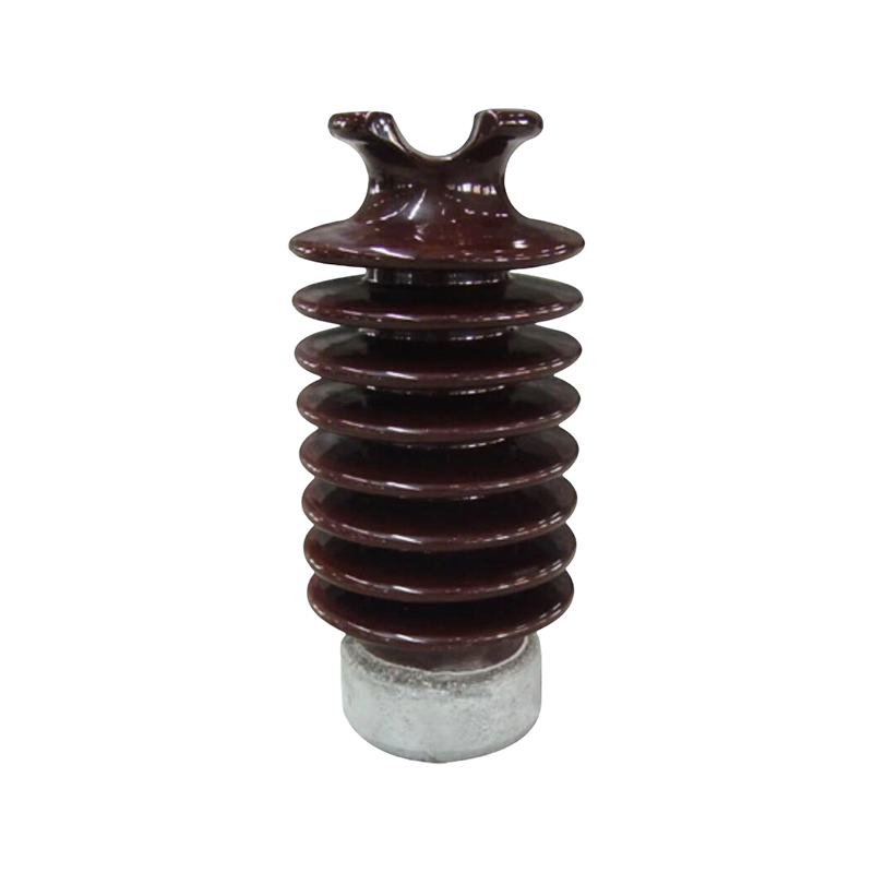
In addition to the PTFE insulation system, silicone rubber creepage extenders can be installed to increase the effective creepage distance. This combination gives the tubular busbar strong resistance to surface tracking, moisture-related flashover, and contamination. With a design operating range that can extend from approximately -60°C to 250°C, depending on the configuration and applicable rating, the product is suitable for severe cold, high-temperature, coastal, chemical, industrial, and outdoor environments.
This article explains the construction, operating principles, performance advantages, manufacturing technology, applications, quality controls, and customization possibilities of PTFE Tubular Bus Bar. It also examines how the product compares with epoxy resin casting and silicone rubber insulation, and why an experienced manufacturer is essential when the busbar forms part of a high-voltage or high-current power system.
1. What Is a PTFE Tubular Bus Bar?
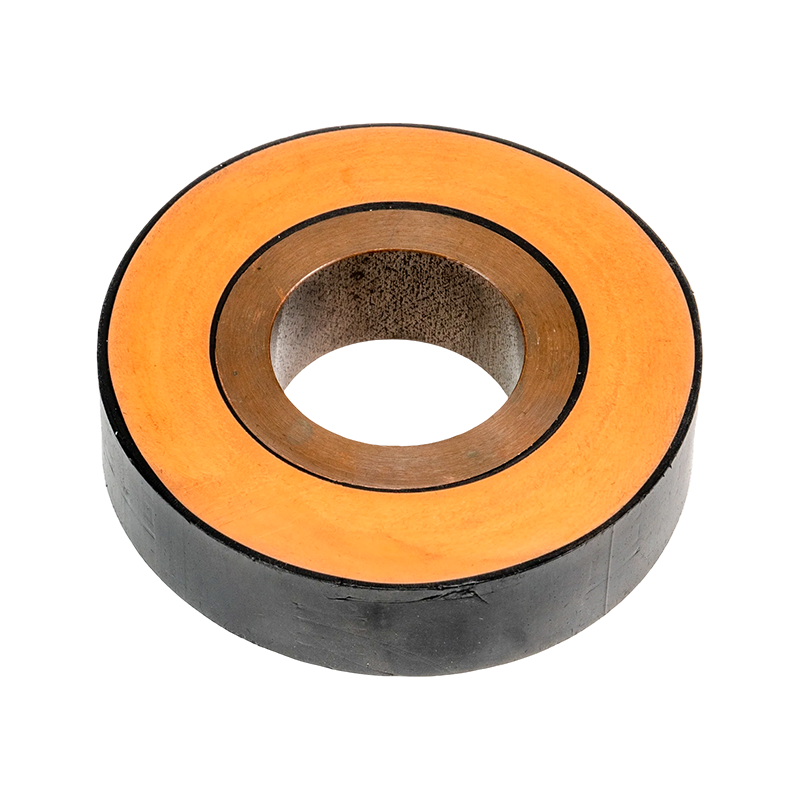
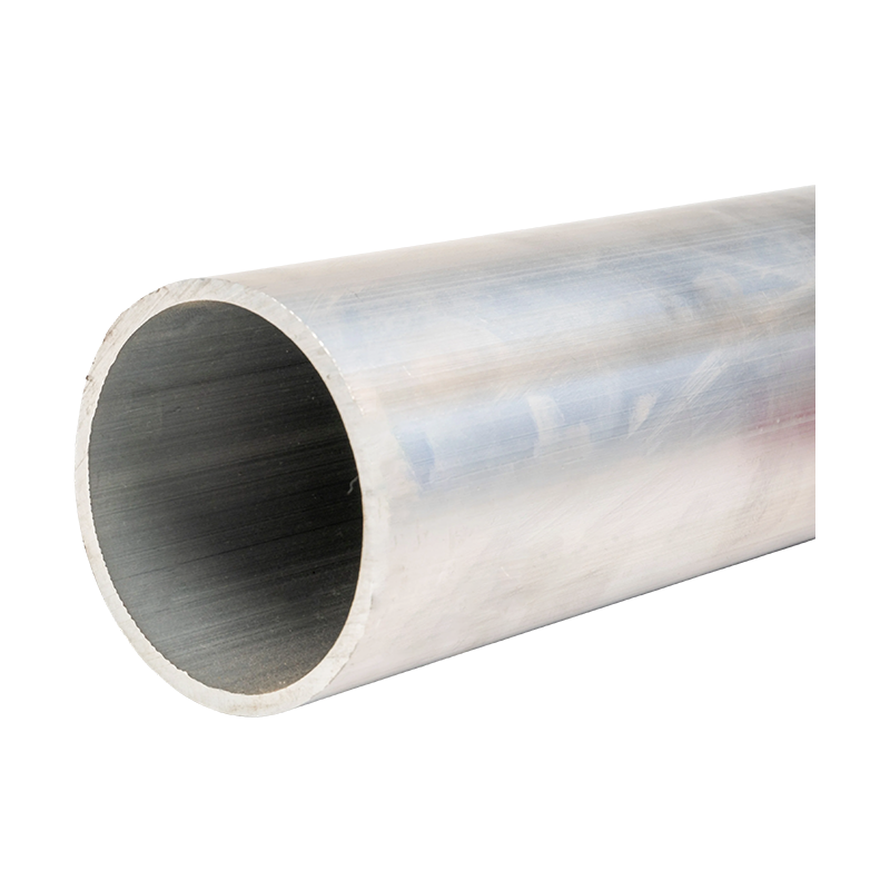
A PTFE Tubular Bus Bar is an insulated tubular conductor assembly designed to distribute or transmit electrical power. It normally consists of a copper or aluminum alloy conductor, a precision-engineered PTFE insulation layer, capacitive screens, grounding provisions, and external protective or creepage-enhancing components. The complete assembly is designed to provide electrical insulation, mechanical stability, environmental protection, and controlled electric-field performance.
Unlike an ordinary bare busbar, the tubular design encloses the conductor within a continuous insulated structure. This reduces the possibility of accidental contact, phase-to-phase faults, and contamination-related failures. Unlike a conventional cable, the tubular busbar can provide a rigid or semi-rigid power connection with a defined geometry and high current-carrying capability. It is therefore suitable for connecting transformers, switchgear, substations, generator systems, industrial equipment, and other high-current installations.
The conductor may be manufactured from copper or aluminum alloy according to current capacity, weight, installation conditions, cost targets, and project specifications. Copper offers high conductivity and strong short-circuit performance. Aluminum alloy provides lower weight and can be advantageous for long spans, elevated structures, and applications where transportation or support loads are important.
The PTFE insulation is the defining feature of this product. PTFE has a low dielectric constant, low dielectric loss, excellent chemical inertness, a very low friction coefficient, and strong resistance to moisture. It remains stable across a broad temperature range and does not easily react with acids, alkalis, salt spray, or many organic solvents. These properties make it particularly valuable in locations where the insulation must remain stable despite thermal cycling, chemical exposure, or difficult maintenance conditions.
1.1 Main Components
The conductor core carries the electrical current. Its cross-sectional area, shape, wall thickness, and alloy selection are calculated according to the continuous current, short-time withstand current, voltage level, heat dissipation, and installation method. The conductor may be tubular, hollow, or formed with a specific profile to optimize electrical and mechanical performance.
The PTFE insulation layer is applied by controlled mechanical winding. Several layers may be used to obtain the required dielectric strength and mechanical protection. The winding process must maintain consistent tension, alignment, overlap, and layer thickness. In high-performance manufacturing, inter-layer tension is controlled to a narrow tolerance, with a target uniformity of approximately ±2% in demanding applications.
Silicone oil between the PTFE layers helps reduce voids and supports a dense, continuous insulating structure. Avoiding air pockets is essential because gas-filled voids can intensify local electric fields and become sites for partial discharge. The manufacturing process therefore places strong emphasis on bubble control, layer compression, and consistent winding geometry.
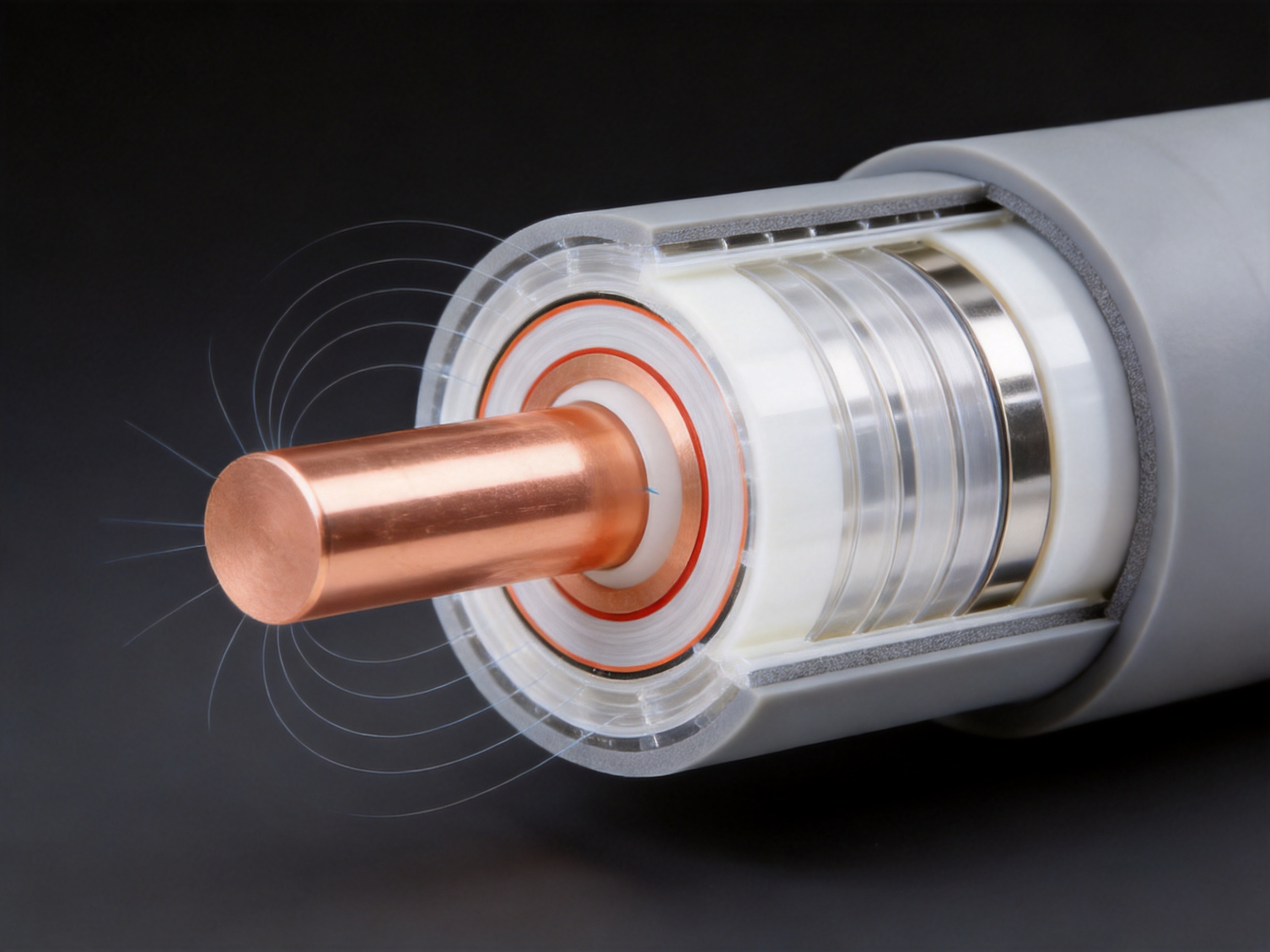
Capacitive screens are integrated into the insulation system to control the electric field. Depending on the voltage class and design, the product may include no fewer than five screens, such as a zero screen, grading screens, and a grounding screen. These layers help distribute voltage more evenly around the conductor and along the insulation, reducing electrical stress concentrations.
Silicone rubber creepage extenders may be fitted to the external surface or at specific connection areas. Their function is to increase creepage distance and improve the product’s resistance to surface leakage under wet, dusty, salty, or polluted conditions. The external surface can also be designed to meet a high ingress protection level, with configurations reaching IP68 when properly integrated with end seals, joints, and connection accessories.
2. Why PTFE Is Suitable for Extreme Environments
Insulation materials used in power equipment must withstand more than the nominal system voltage. They must also tolerate temperature changes, mechanical movement, humidity, pollution, ultraviolet exposure, chemical contact, and long-term electrical aging. PTFE offers a combination of properties that is difficult to achieve with many conventional materials.
2.1 Wide Temperature Capability
PTFE remains functional over a broad temperature range. The product described for extreme-environment use is designed for operating conditions from approximately -60°C to 250°C. Actual permitted temperature depends on conductor material, current loading, connection design, mechanical supports, installation environment, and the relevant technical standard. Some high-voltage configurations may use a more conservative continuous operating range, such as -60°C to 200°C, to maintain an appropriate electrical and thermal safety margin.
At low temperatures, brittle insulation can crack when exposed to vibration or mechanical movement. PTFE retains useful flexibility and stability in very cold environments, making it suitable for outdoor substations, energy infrastructure in northern climates, cold storage facilities, and high-altitude installations.
At elevated temperatures, the insulation must resist softening, deformation, and accelerated aging. PTFE provides good thermal stability and can support applications near high-temperature equipment when the conductor temperature and joint temperature are properly calculated. It is particularly useful where large daily temperature variations create repeated expansion and contraction cycles.
2.2 Chemical and Corrosion Resistance
Industrial power equipment may be exposed to acids, alkalis, solvents, oil mist, salt spray, cleaning chemicals, and process vapors. Some insulation materials absorb moisture or gradually degrade after long exposure to aggressive substances. PTFE is chemically inert against a broad range of common corrosive agents. This helps preserve insulation thickness, surface quality, and dielectric performance.
The corrosion resistance of the insulation is especially valuable in chemical plants, coastal substations, wastewater treatment facilities, metal processing plants, marine infrastructure, and industrial workshops. PTFE does not replace the need for proper conductor protection, suitable terminals, and corrosion-resistant hardware, but it provides a strong first line of defense around the energized conductor.
2.3 Moisture and Pollution Resistance
Moisture can reduce surface resistance and contribute to leakage current, tracking, and flashover. Dust and salt deposits may create a conductive film when wet. PTFE has low water absorption and a non-stick surface that makes contamination less likely to form a persistent bond. When combined with silicone rubber creepage extenders and sealed connection systems, the tubular busbar can provide strong resistance to wet and polluted environments.
A protection rating reaching IP68 may be available for suitable designs. IP68 performance depends on the complete assembly rather than the insulation material alone. End fittings, joints, inspection points, seals, and installation practices must all be designed to prevent water ingress. For this reason, manufacturers should validate the completed product, not just individual components.
2.4 Low Friction and Reduced Mechanical Stress
PTFE has an extremely low coefficient of friction. This property is useful during manufacturing because it supports smooth film handling and controlled layering. It can also reduce mechanical stress between insulation layers during thermal expansion and contraction. Lower friction may help limit abrasion and localized movement when the busbar experiences vibration or temperature cycling.
Low friction does not mean that the busbar can be installed without mechanical supports. Proper supports, bending limitations, joint alignment, and expansion provisions remain necessary. However, the material’s friction characteristics can contribute to a more stable insulation structure when the complete mechanical design is correctly executed.
3. Electrical Performance and Field Control
High-voltage insulation must withstand the normal operating voltage, temporary overvoltages, switching impulses, lightning impulses, and local electric-field concentrations. A thick insulation layer alone does not guarantee reliable performance. The geometry, interfaces, screen arrangement, surface condition, and absence of voids are all important.
3.1 High Dielectric Strength
The PTFE insulation system can provide a dielectric strength of approximately 35 kV/mm or higher under suitable test conditions and material specifications. This figure represents a material or insulation-system characteristic, not a universal system voltage rating. The final voltage rating depends on insulation thickness, screen design, conductor geometry, manufacturing quality, test requirements, creepage distance, clearances, and accessories.
High dielectric strength allows the designer to achieve the required insulation level without using an unnecessarily bulky structure. A compact design can simplify installation in switchgear rooms, cable trenches, substations, and equipment interfaces. It may also reduce the overall weight and support requirements of the power connection.
3.2 Low Dielectric Loss
PTFE has a low dielectric constant and low dielectric loss. A low dielectric loss factor, potentially at or below 0.0002 at 50 Hz for a qualified material system, helps minimize energy dissipation within the insulation. This is useful in long-duration, high-voltage operation because lower dielectric losses can reduce heating and improve system efficiency.
Actual dielectric loss depends on the complete insulation structure, frequency, temperature, manufacturing quality, screen arrangement, and test method. The manufacturer should therefore provide test data for the actual product configuration rather than relying only on general material values.
3.3 Capacitive Screen Arrangement
Capacitive screens form an important part of the product’s electrical design. Without adequate field control, the electric field may become concentrated at conductor edges, insulation interfaces, joints, or termination points. These concentrations can increase partial discharge activity and accelerate insulation aging.
A zero screen can establish a defined electrical reference within the insulation system. Grading screens help divide the voltage stress into controlled sections. A grounding screen provides a safe external reference and can support monitoring or protection functions. The use of multiple screens allows the manufacturer to tailor the electric-field distribution to the voltage class and geometry of the busbar.
Screen continuity is essential. A screen that is incorrectly overlapped, damaged, poorly connected, or separated from the intended reference point can produce unexpected electrical stress. Quality control must therefore include dimensional inspection, continuity testing, grounding verification, and high-voltage testing of the finished assembly.
3.4 Partial Discharge Control
Partial discharge is a localized electrical discharge that does not completely bridge the insulation between electrodes. Repeated partial discharge can gradually damage insulation and eventually lead to failure. The risk increases when air pockets, foreign particles, sharp edges, moisture, or poor interfaces are present.
The precision PTFE winding process is intended to produce a dense and uniform insulation system. Silicone oil between layers supports a gas-free structure and reduces the likelihood of void-related discharge. Ultrasonic assistance may be used during manufacturing to identify or control bubbles. The combination of careful winding, screen design, clean processing, and electrical testing supports improved partial discharge performance.
4. Performance Advantages Over Conventional Insulated Busbars
PTFE Tubular Bus Bar is not intended to replace every other busbar type. Epoxy resin, silicone rubber, PVC, and other insulation systems can be appropriate for many applications. The advantage of PTFE becomes most apparent when the project requires a wide temperature range, chemical resistance, low dielectric loss, low moisture absorption, and stable insulation in difficult environments.
| Performance Category | PTFE Tubular Bus Bar | Epoxy Resin Casting Busbar | Silicone Rubber Insulated Busbar |
|---|---|---|---|
| Typical temperature capability | Approximately -60°C to 200°C or higher, with selected designs reaching 250°C | Approximately -30°C to 130°C | Approximately -40°C to 120°C |
| Dielectric strength | Approximately 35 kV/mm or higher under specified conditions | Approximately 30 kV/mm under specified conditions | Approximately 25 kV/mm under specified conditions |
| Dielectric loss | Very low; qualified systems may reach approximately 0.0002 at 50 Hz | Higher than PTFE in typical configurations | Moderate and dependent on compound formulation |
| Chemical resistance | Excellent against acids, alkalis, salt spray, and many solvents | Good against selected agents, but dependent on resin formulation | Good, but may be affected by particular chemicals and oils |
| Moisture absorption | Very low | Low to moderate depending on formulation and defects | Low, but surface contamination must be managed |
| Electric-field control | Multiple capacitive screens available | Usually based on casting geometry and embedded screens | Depends on design and screen arrangement |
| Extreme-environment suitability | Very high for properly engineered configurations | Good for standard industrial environments | Good for flexible and outdoor applications |
| Relative material cost | High | Moderate | Moderate to high |
Epoxy resin casting offers excellent rigidity, dimensional stability, and efficient mass production. It is widely used in medium-voltage systems and indoor equipment. However, epoxy systems may have more limited temperature flexibility and can be vulnerable to stress concentration or cracking if the casting process, thermal design, or mechanical structure is not properly controlled.
Silicone rubber provides flexibility, weather resistance, and useful outdoor performance. It is often selected where movement, vibration, or complex routing is important. Compared with PTFE, however, its dielectric, thermal, and chemical performance depends strongly on compound formulation and the surrounding design. PTFE is especially attractive when very low dielectric loss and exceptional chemical inertness are priorities.
The main disadvantage of PTFE is cost. PTFE raw material is more expensive than many conventional insulation materials, and the precision winding process requires specialized equipment, skilled operators, and careful inspection. PTFE is also difficult to recycle or degrade, so responsible material management is important. These disadvantages should be evaluated against the cost of maintenance, downtime, replacement, and failure in a severe operating environment.
5. Advanced Manufacturing Process
The performance of a PTFE Tubular Bus Bar depends heavily on manufacturing discipline. The material itself has excellent properties, but inconsistent winding, poor screen placement, contamination, or inadequate joint sealing can undermine the final product. A qualified manufacturer therefore combines material control, mechanical precision, electrical engineering, and inspection throughout the production cycle.
5.1 Engineering and Design Review
Manufacturing begins with a technical review of the project requirements. Engineers evaluate rated voltage, continuous current, short-circuit current, frequency, conductor material, ambient temperature, installation height, pollution level, chemical exposure, support spacing, bending requirements, connection type, and required protection rating.
The design team then calculates conductor dimensions, thermal rise, insulation thickness, screen arrangement, creepage distance, mechanical supports, and terminal geometry. Computer-aided design and electrical-field analysis may be used to identify high-stress regions around joints, elbows, terminations, and changes in diameter.
For customized products, the engineering review also considers transformer terminals, switchgear interfaces, cable trench dimensions, vertical or horizontal routing, expansion requirements, and site assembly limitations. This stage helps prevent costly modifications after production.
5.2 Conductor Preparation
Copper or aluminum alloy conductors are inspected for dimensional accuracy, surface quality, conductivity, and mechanical integrity. The conductor surface must be clean and free from sharp burrs, oil, oxidation, and foreign particles that could damage the insulation or create electrical stress.
CNC machining can be used to produce accurate conductor ends, connection holes, joint surfaces, and special terminal profiles. Dimensional control is important because even small irregularities may affect screen alignment, joint fit, or contact resistance.
For aluminum conductors, surface treatment and connection design require particular attention. Aluminum oxide can increase contact resistance, so suitable preparation, joint compounds, plating, washers, or transition connectors may be required. For copper conductors, the manufacturing process must also control oxidation and surface contamination.
5.3 PTFE Film Preparation
PTFE film must be stored and handled in a clean environment. The film width, thickness, surface condition, and batch information should be verified before use. Damage, contamination, wrinkles, and edge defects can affect the continuity of the insulation layer.
The film is fed into a controlled winding system. Tension control is a critical parameter. Excessive tension may deform or stretch the film, while insufficient tension may create wrinkles, gaps, or unstable overlaps. Advanced winding equipment maintains consistent tension and alignment throughout the length of the busbar.
5.4 Precision Mechanical Winding
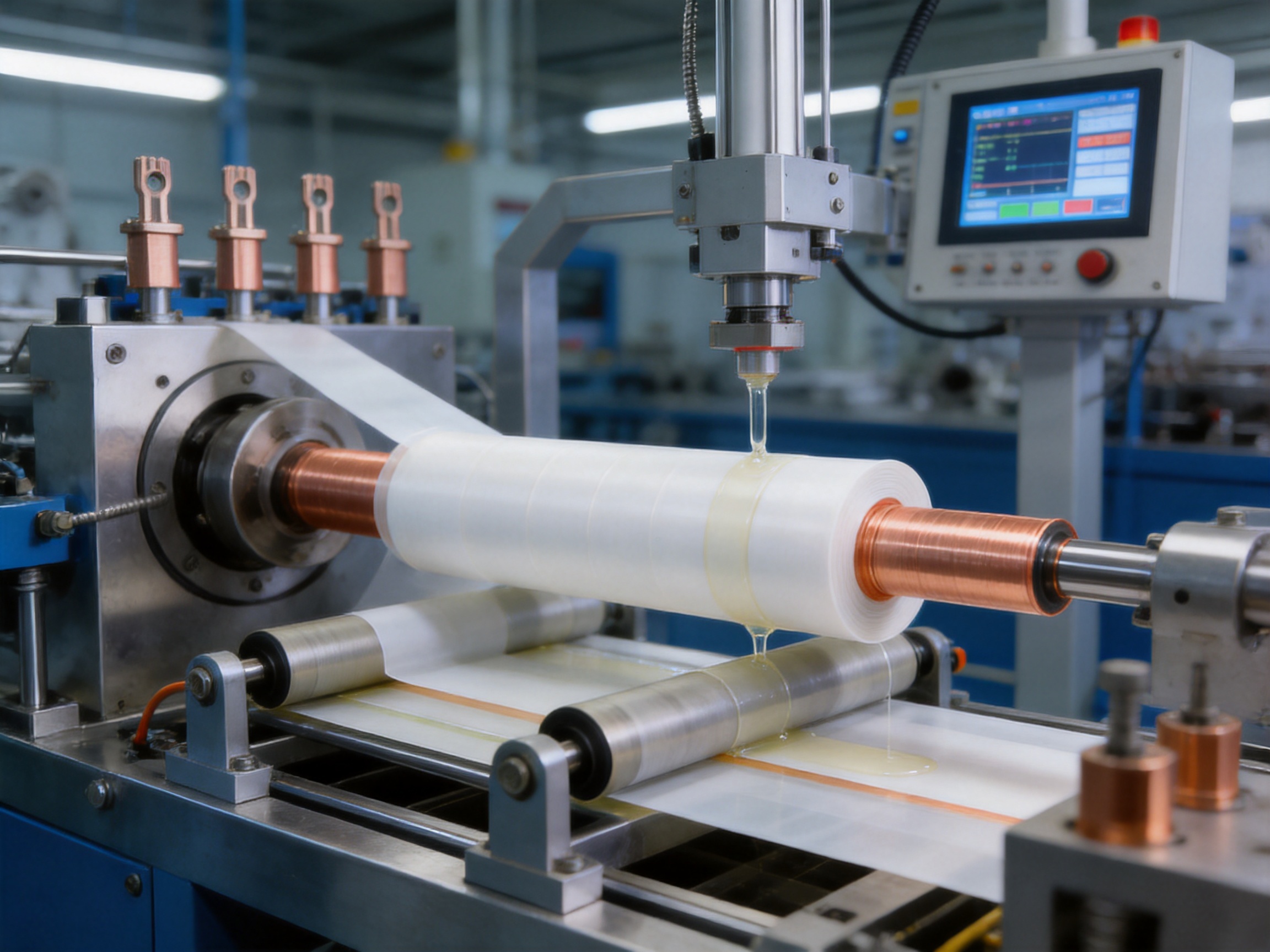
During winding, PTFE film is applied in multiple layers around the conductor. The overlap ratio, winding angle, layer sequence, and axial position are controlled according to the design. The objective is to create a uniform insulation wall with no discontinuities or weak regions.
Inter-layer tension uniformity may be controlled within approximately ±2% for demanding configurations. This narrow tolerance supports consistent compression and reduces the risk of localized voids. Automated monitoring can record tension, speed, overlap, temperature, and other process parameters for traceability.
The winding process must also accommodate screen layers. Each screen is positioned at the correct radial and axial location, with controlled overlaps and reliable electrical continuity. The zero screen, grading screens, and grounding screen must not be confused or incorrectly connected. Process documentation and visual inspection are required at every critical stage.
5.5 Bubble and Void Control
Air bubbles and voids are among the most serious risks in high-voltage insulation. A void has a different dielectric behavior from the surrounding PTFE and silicone oil. Under voltage stress, the electric field may concentrate within the void, increasing the risk of partial discharge.
Manufacturers may use ultrasonic assistance and controlled compression to identify or reduce bubbles during winding. Clean-room practices, stable material temperature, controlled winding speed, and proper layer pressure all contribute to a dense insulation structure. The completed product may undergo partial discharge testing or other dielectric inspections to verify the result.
5.6 Inter-Layer Adhesion Treatment
PTFE has a very low surface energy, which means that layers do not naturally bond strongly to one another. This characteristic is beneficial for low friction but creates a manufacturing challenge when a stable multi-layer insulation structure is required.
Special surface treatment agents or carefully controlled mechanical methods may be used to improve inter-layer stability. The treatment must be compatible with the electrical, thermal, and chemical requirements of the product. Excessive treatment, contamination, or uneven application may reduce insulation performance, so process control and verification are essential.
5.7 Silicone Oil Application
Silicone oil is applied between selected PTFE layers to support a dense, gas-free continuous insulation system. The amount and distribution must be controlled. Too little material may leave microscopic gaps, while too much may affect dimensional stability, handling, or sealing.
The oil must be clean and compatible with PTFE, screens, seals, and other internal materials. Manufacturers should control viscosity, storage conditions, application rate, and cleanliness. The final structure must prevent migration or leakage during normal operation and temperature cycling.
5.8 Installation of Creepage Extenders
Silicone rubber creepage extenders are installed where increased surface leakage distance is required. Their profile can be adjusted according to voltage level, pollution severity, orientation, and available space. The extenders should be securely fitted without creating sharp edges, trapped moisture, or mechanical stress on the insulation.
In coastal, industrial, and dusty environments, creepage design is particularly important. A longer surface path makes it more difficult for contamination and moisture to create a continuous conductive route. This improves resistance to tracking and surface flashover.
5.9 End Terminations and Sealing
The ends of the tubular busbar are prepared for connection to transformers, switchgear, generators, or other equipment. Terminations must preserve conductor conductivity while maintaining insulation continuity and field control. Stress cones, screen connections, sealing elements, and grounding points are positioned according to the electrical design.
Sealing is essential where a high ingress protection rating is required. The end structure must prevent water, dust, and chemicals from entering the insulation system. Gaskets, molded components, compression fittings, and protective covers are selected according to the operating environment.
5.10 CNC Machining and Automated Assembly
Advanced CNC machining improves the accuracy of conductor joints, support components, flanges, and terminal parts. Automated assembly technologies help maintain repeatability in screen installation, sealing, fastening, and dimensional alignment. These processes reduce variation between production batches and provide better control for customized products.
A modern manufacturing line may combine vacuum casting equipment for other product families, CNC machining centers, automated assembly stations, precision winding equipment, electrical test systems, and digital production records. This broad capability allows the manufacturer to develop complete busbar solutions rather than supplying only a basic conductor section.
6. Quality Assurance and Testing
Quality assurance must cover raw materials, intermediate processes, finished assemblies, and documentation. A product designed for high-voltage service cannot rely on visual inspection alone. Electrical, mechanical, dimensional, thermal, and environmental checks are necessary.
6.1 Material Inspection
Incoming copper and aluminum alloy materials should be checked for conductivity, dimensions, surface condition, and chemical or mechanical certificates. PTFE film should be inspected for thickness, width, cleanliness, tensile properties, and surface defects. Silicone rubber components should be verified for hardness, dimensional accuracy, and material compatibility.
6.2 Dimensional Inspection
Finished busbars are inspected for outer diameter, insulation thickness, conductor alignment, screen position, terminal dimensions, bend radius, flange location, and overall length. Accurate dimensions are essential for connection to transformers and switchgear. A small mismatch at a terminal can create mechanical stress or prevent proper sealing.
6.3 Electrical Testing
High-voltage withstand testing verifies that the insulation can resist the specified test voltage for the required duration. Insulation resistance testing identifies leakage paths or contamination. Screen continuity and grounding tests verify the intended electrical structure.
Partial discharge testing may be performed to detect internal defects that are not visible externally. Dielectric loss and capacitance measurements can provide additional information about the insulation condition. Test voltage, test duration, acceptance criteria, and test environment should be defined according to the project specification and applicable standards.
6.4 Mechanical and Environmental Verification
Mechanical checks may include terminal pull tests, support load verification, vibration evaluation, bending assessment, and dimensional stability checks. For outdoor or chemically exposed installations, environmental testing may include temperature cycling, humidity exposure, salt spray, water ingress, and contamination evaluation.
When an IP68 configuration is specified, the complete assembly should be evaluated for protection against dust and prolonged water immersion under the defined test conditions. The rating applies to the tested design and installation method, so field assembly must follow the manufacturer’s instructions.
6.5 Third-Party Validation
Testing collaboration with independent institutions can provide additional confidence in product safety and performance. Third-party verification is particularly useful for high-voltage projects, infrastructure contracts, utility applications, and projects requiring formal compliance documentation.
A strong manufacturer should be able to provide inspection records, routine test reports, material certificates, drawings, installation instructions, and traceability information. These documents support commissioning, maintenance, and future troubleshooting.
7. Applications of PTFE Tubular Bus Bar
7.1 Outdoor Substations
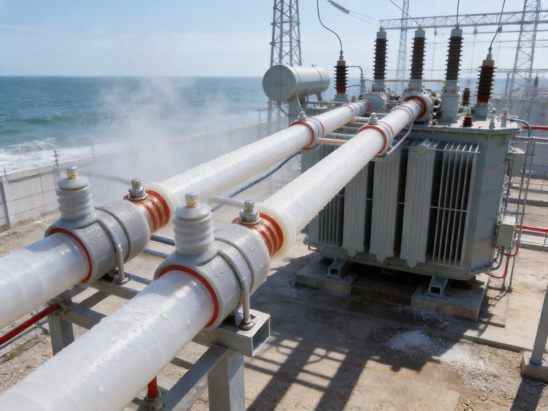
Outdoor substations are exposed to rain, sunlight, dust, salt, wind, and wide temperature changes. PTFE Tubular Bus Bar can provide a protected connection between transformers, switchgear, and other high-voltage equipment. Its field-control system and creepage extenders are valuable where pollution and humidity increase the risk of surface discharge.
7.2 Chemical and Process Industries
Chemical plants often contain corrosive vapors and cleaning agents that can attack conventional insulation or exposed metalwork. PTFE’s chemical resistance makes the product suitable for selected connections in chemical processing, pharmaceutical production, wastewater treatment, and industrial laboratories.
7.3 Coastal and Marine Infrastructure
Salt spray can create conductive contamination on exposed electrical equipment. The combination of PTFE insulation, sealed construction, capacitive screens, and extended creepage paths can improve reliability in coastal substations, ports, shipyard facilities, desalination plants, and marine infrastructure.
7.4 High-Temperature Industrial Areas
Steel mills, glass plants, foundries, ceramic factories, and other heavy industries may expose electrical equipment to radiant heat and elevated ambient temperatures. A properly rated PTFE tubular busbar can be routed near high-temperature equipment while maintaining insulation performance, provided that conductor temperature, heat dissipation, and connection ratings are fully evaluated.
7.5 Renewable Energy and Wind Power
Wind power installations experience vibration, temperature cycling, humidity, and limited maintenance access. Tubular busbar systems can provide compact high-current connections within wind turbines, substations, and renewable energy collection systems. The mechanical design must account for movement, support spacing, installation access, and vibration isolation.
7.6 Rail Transit and Large Facilities
Rail transit systems, airports, data centers, commercial complexes, and industrial campuses require reliable power distribution with controlled installation space. A tubular busbar can reduce the need for multiple parallel cables and provide a clean, organized route between major electrical equipment.
7.7 Transformer-to-Switchgear Connections
One of the most common applications is the direct connection from the low-voltage or medium-voltage terminals of a main transformer to switchgear in a control room. The arrangement is suitable for large currents and can create a neat, compact, and fully insulated connection. Correct alignment, flexible expansion provisions, and proper termination design are important.
7.8 Cable Trenches and Cable Mezzanines
The busbar may be routed through an underground cable trench or a cable mezzanine. This arrangement is useful when traditional cable routing is difficult or when the project requires a defined, compact power path. It can also connect multiple switchgear sections while reducing exposed energized surfaces.
8. Installation and System Design Considerations
Even a high-performance busbar can fail if it is incorrectly installed. The installation team should review drawings, transportation instructions, lifting points, support positions, joint procedures, grounding requirements, and minimum bending or alignment limits before work begins.
Support spacing must be calculated according to the busbar weight, short-circuit forces, span length, vibration, and installation orientation. Supports should not place excessive pressure on the insulation or force the conductor out of alignment. Where thermal expansion is expected, expansion joints or suitable flexible connections may be required.
Connection surfaces should be clean and correctly prepared. Bolted joints must use the specified hardware and tightening torque. Contact resistance should be minimized, especially for high-current aluminum connections. Grounding screens and external metal components must be connected according to the electrical design.
Terminations should be protected from sharp tools, uncontrolled bending, impact, and contamination. Seals must be correctly seated, and any field-applied compounds must be compatible with PTFE, silicone rubber, conductor metals, and the operating environment.
After installation, the system should undergo visual inspection, insulation resistance testing, screen continuity verification, grounding checks, and the required high-voltage tests. Test results should be recorded as part of the commissioning documentation.
9. Customization Capabilities
Electrical projects rarely use a single standard dimension. A custom PTFE Tubular Bus Bar can be engineered for specific conductor sizes, insulation thicknesses, voltage levels, current ratings, lengths, terminal configurations, support arrangements, and environmental conditions.
Customization may include copper or aluminum conductors, different tubular diameters, straight sections, offset sections, elbows, expansion sections, transformer interfaces, switchgear interfaces, flexible joints, grounding connections, inspection points, and special sealing structures.
The manufacturer can also adjust the screen configuration according to the voltage gradient and equipment geometry. In installations with severe pollution, additional creepage extenders or specially shaped external profiles may be recommended. In high-temperature projects, conductor cross-section, ventilation, support material, and thermal clearances must be considered together.
For a successful custom design, the customer should provide rated voltage, rated current, short-circuit current, system frequency, installation drawings, ambient temperature, altitude, pollution level, chemical exposure, indoor or outdoor conditions, required ingress protection, connection dimensions, and applicable standards. Detailed information at the beginning of the project reduces design changes and improves delivery efficiency.
10. Manufacturing Strengths of Jiangsu Wopeng Power Technology
Jiangsu Wopeng Power Technology Co., Ltd. is a specialized high-tech enterprise established in 2018 and focused on high- and low-voltage busbar systems. Its product range includes 35kV epoxy resin vacuum-cast tubular busbars, low-voltage cast resin busways, copper and aluminum tubular busbars, wind power tubular busbars, compact busbar systems, and sliding contact line systems.
This product range provides an important engineering advantage. A customer may require different busbar technologies across one project or across several operating locations. A manufacturer experienced in multiple busbar structures can compare alternatives and recommend a solution based on current, voltage, environment, installation space, and cost rather than promoting only one construction method.
Wopeng has developed a team of engineers, technical specialists, and production professionals with experience in power equipment technology. Its manufacturing capabilities include vacuum casting systems, CNC machining equipment, automated assembly technologies, and standardized inspection processes. These capabilities support the production of both standard and customized busbar assemblies.
The company’s quality process includes high-voltage tests, insulation tests, mechanical verification, dimensional checks, and routine inspections. Cooperation with third-party testing institutions provides independent validation for selected products and projects. Such testing is valuable when equipment is used in substations, power generation facilities, industrial plants, renewable energy systems, rail transit, and large commercial infrastructure.
Wopeng products operate in more than 17 provinces and across multiple industrial sectors. This field experience helps the company understand practical installation requirements, transportation challenges, environmental conditions, maintenance expectations, and interface issues between transformers, switchgear, and busbar systems.
For PTFE Tubular Bus Bar projects, the most important manufacturing strengths include process control, customized engineering, conductor machining, screen integration, insulation inspection, and complete project documentation. These strengths help transform PTFE’s material advantages into a reliable finished product.
11. Maintenance and Service Life
PTFE Tubular Bus Bar is designed to reduce maintenance requirements, but it should not be treated as maintenance-free. Periodic inspections should verify external condition, support integrity, termination sealing, grounding continuity, signs of contamination, and evidence of overheating.
Thermal imaging can help identify abnormal heating at joints and terminals. Insulation resistance and partial discharge measurements may be included in planned maintenance programs, particularly for high-voltage or mission-critical installations. Inspection frequency should reflect system voltage, operating load, environment, importance, and local regulations.
In normal high-voltage operating conditions, a service life of approximately 35 to 45 years may be achievable when the product is correctly designed, installed, and maintained. Actual service life depends on thermal aging, electrical stress, mechanical vibration, chemical exposure, ultraviolet radiation, joint condition, and maintenance quality.
The use of PTFE does not eliminate the need for correct system protection. Overcurrent protection, surge protection, grounding, clearance, and coordination with connected equipment remain essential. A durable insulation material must still be used within a complete and properly protected electrical system.
12. Economic Evaluation
The initial price of PTFE Tubular Bus Bar is generally higher than that of many conventional insulated busbars. The higher cost reflects the price of PTFE raw material, precision film winding, special treatment for inter-layer stability, screen integration, specialized inspection, and customized engineering.
However, purchase price is only one part of the total cost of ownership. In severe environments, a lower-cost insulation system may require more frequent inspection, cleaning, replacement, or repair. An insulation failure can also create production losses, equipment damage, safety risks, and extended downtime.
PTFE can provide economic value when the installation demands very long service life, high temperature capability, strong chemical resistance, low dielectric loss, and limited access for maintenance. The appropriate comparison should include installation cost, support requirements, maintenance labor, outage risk, replacement difficulty, energy losses, and expected service life.
Because PTFE is difficult to recycle and can create environmental processing challenges, responsible material selection and end-of-life planning should be included in the project evaluation. Manufacturers and users should manage production waste, damaged components, and removed insulation in accordance with applicable environmental requirements.
13. How to Select the Right Product
13.1 Confirm Electrical Requirements
Begin with rated voltage, rated current, system frequency, short-circuit withstand current, insulation level, and required clearances. Do not select a busbar solely by conductor size. The insulation system, screen arrangement, terminations, and connection accessories must all match the electrical duty.
13.2 Evaluate the Environment
Record minimum and maximum ambient temperature, humidity, altitude, salt exposure, chemical vapors, dust, ultraviolet radiation, vibration, and water exposure. These factors determine the insulation material, creepage design, seals, external protection, and support system.
13.3 Check Installation Geometry
Provide accurate drawings showing transformer terminals, switchgear terminals, cable trenches, mezzanines, support locations, elevations, offsets, and access restrictions. A custom manufacturer can use this information to produce correctly dimensioned sections and reduce field modifications.
13.4 Review Manufacturer Capability
A reliable supplier should have documented experience in insulated busbar systems, appropriate production equipment, electrical testing capability, skilled technical personnel, and a formal quality management process. Evidence may include test reports, inspection records, reference projects, technical drawings, and installation guidelines.
13.5 Confirm Documentation and Support
Before purchase, confirm that the supplier can provide product specifications, drawings, material information, test certificates, packing instructions, installation procedures, maintenance recommendations, and after-sales technical support. Documentation is particularly important for equipment that will be integrated into a larger high-voltage system.
14. Frequently Asked Questions
Q1: What is the main advantage of PTFE Tubular Bus Bar?
The main advantage is the combination of high dielectric performance, very broad temperature capability, chemical resistance, low dielectric loss, low moisture absorption, and controlled electric-field distribution. This combination makes it suitable for severe environments where ordinary insulation may experience accelerated aging.
Q2: What voltage levels are suitable for this product?
PTFE Tubular Bus Bar can be engineered for high-voltage applications, including systems in the approximate range of 110kV to 500kV in suitable configurations. The exact voltage rating must be confirmed through insulation design, screen arrangement, testing, terminal construction, and the applicable project standard.
Q3: Can the product operate at 250°C?
Selected designs can be specified for operating temperatures approaching 250°C. The permitted temperature depends on the conductor, current loading, joint components, seals, screens, support materials, and system design. A project-specific thermal calculation and technical confirmation are required before operation at the upper limit.
Q4: Why are capacitive screens needed?
Capacitive screens control and distribute electric-field stress within the insulation system. They reduce the possibility of concentrated voltage gradients at interfaces, terminations, and changes in geometry. Multiple screens can be arranged as zero, grading, and grounding screens according to the voltage and construction requirements.
Q5: What is the function of silicone oil between PTFE layers?
Silicone oil helps create a dense, continuous, and substantially gas-free insulation structure between PTFE layers. It supports void control and reduces the risk of local electrical stress caused by air pockets. Its cleanliness, compatibility, and application quantity must be controlled during manufacturing.
Q6: Is PTFE better than epoxy resin for every application?
No. Epoxy resin can be an economical and highly reliable choice for many indoor medium-voltage applications. PTFE is advantageous when the project requires exceptionally broad temperature capability, chemical resistance, low dielectric loss, or extreme-environment performance. Selection should be based on the full electrical, mechanical, environmental, and economic requirements.
Q7: Can PTFE Tubular Bus Bar be customized?
Yes. Customization can include conductor material, conductor size, insulation thickness, overall diameter, length, bends, offsets, terminal dimensions, screen structure, creepage extenders, seals, grounding connections, and protection level. A manufacturer should review the project drawings and technical data before confirming the design.
Q8: Can the product be used outdoors?
Yes, when it is designed with suitable weather protection, creepage distance, sealing, grounding, and mechanical supports. Outdoor applications should account for rain, salt spray, dust, ultraviolet exposure, wind, temperature cycling, and possible water immersion.
Q9: Does IP68 apply to every PTFE tubular busbar?
No. IP68 is a rating for a complete tested enclosure or assembly. It depends on end seals, joints, covers, interfaces, and installation procedures. The manufacturer must confirm the protection level for the specific configuration ordered.
Q10: How long can the product last?
Under properly designed, installed, and maintained conditions, a service life of approximately 35 to 45 years may be achievable. Actual life depends on electrical stress, thermal exposure, chemical conditions, vibration, joint performance, and maintenance practices.
Q11: What tests should be requested before shipment?
Typical tests include dimensional inspection, conductor resistance or conductivity verification, insulation resistance, high-voltage withstand, screen continuity, grounding verification, partial discharge evaluation where applicable, mechanical checks, and sealing or ingress protection verification for specified designs.
Q12: Why should an experienced manufacturer be selected?
The performance of the product depends on more than the PTFE material. Precision winding, tension control, bubble reduction, screen placement, inter-layer treatment, terminal machining, sealing, testing, and documentation all affect reliability. An experienced manufacturer can coordinate these factors and provide a complete engineered solution.
15. Conclusion
PTFE Tubular Bus Bar is a specialized solution for power transmission systems that operate under severe electrical, thermal, mechanical, or chemical conditions. Its PTFE film insulation, silicone oil-assisted layer structure, multiple capacitive screens, silicone rubber creepage extenders, and sealed tubular construction provide a combination of performance characteristics that conventional insulated busbars may not match.
The product offers strong dielectric strength, low dielectric loss, wide temperature adaptability, excellent chemical resistance, low moisture absorption, and improved electric-field control. These advantages are especially relevant to substations, chemical facilities, coastal infrastructure, renewable energy systems, heavy industry, rail transit, and other critical power installations.
At the same time, PTFE Tubular Bus Bar requires advanced manufacturing and careful quality control. Precise winding tension, bubble control, inter-layer treatment, screen continuity, conductor machining, termination design, and high-voltage testing are essential. The higher initial cost should be evaluated against long-term reliability, reduced maintenance, improved environmental resistance, and the cost of electrical failure.
Jiangsu Wopeng Power Technology combines engineering experience, specialized production equipment, CNC machining, automated assembly, electrical testing, and customized busbar development. Its broad product portfolio and project experience allow customers to select PTFE tubular busbars alongside other suitable insulated busbar technologies. For demanding power systems, this combination of material performance and manufacturing capability can provide a safer, more stable, and more durable power transmission solution.
References
1. IEC 60840, Power Cables with Extruded Insulation and Their Accessories for Rated Voltages Above 30 kV up to 150 kV.
2. IEC 62271 Series, High-Voltage Switchgear and Controlgear.
3. IEC 60071 Series, Insulation Coordination.
4. IEC 60529, Degrees of Protection Provided by Enclosures.
5. IEC 60270, High-Voltage Test Techniques and Partial Discharge Measurements.
6. ASTM D149, Standard Test Method for Dielectric Breakdown Voltage and Dielectric Strength of Solid Electrical Insulating Materials.
7. ASTM D257, Standard Test Methods for DC Resistance or Conductance of Insulating Materials.
8. Technical data supplied for PTFE Tubular Bus Bar design, insulation construction, temperature performance, and application engineering.
9. Manufacturer quality-control procedures for conductor preparation, PTFE film winding, capacitive screen installation, electrical testing, and final inspection.
Product: PTFE Tubular Bus Bar




-
 +86-180 3625 3000
-
 admin@wpbusbar.com
-
 No. 8, Yanjin Road, Chengxi Industrial Park, Shanyang Town, Baoying County, Yangzhou City, Jiangsu Province, China
Copyright © Jiangsu Wopeng Power Technology Co., Ltd.
All Rights Reserved.
 Custom Insulated Bus Bar Manufacturer
Tubular Busbar System Factory
Custom Insulated Bus Bar Manufacturer
Tubular Busbar System Factory