

 EN
EN

 English
 русский
 Français
 Español
 عربى
عربى
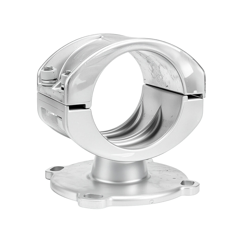
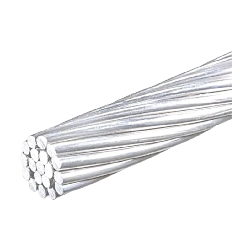
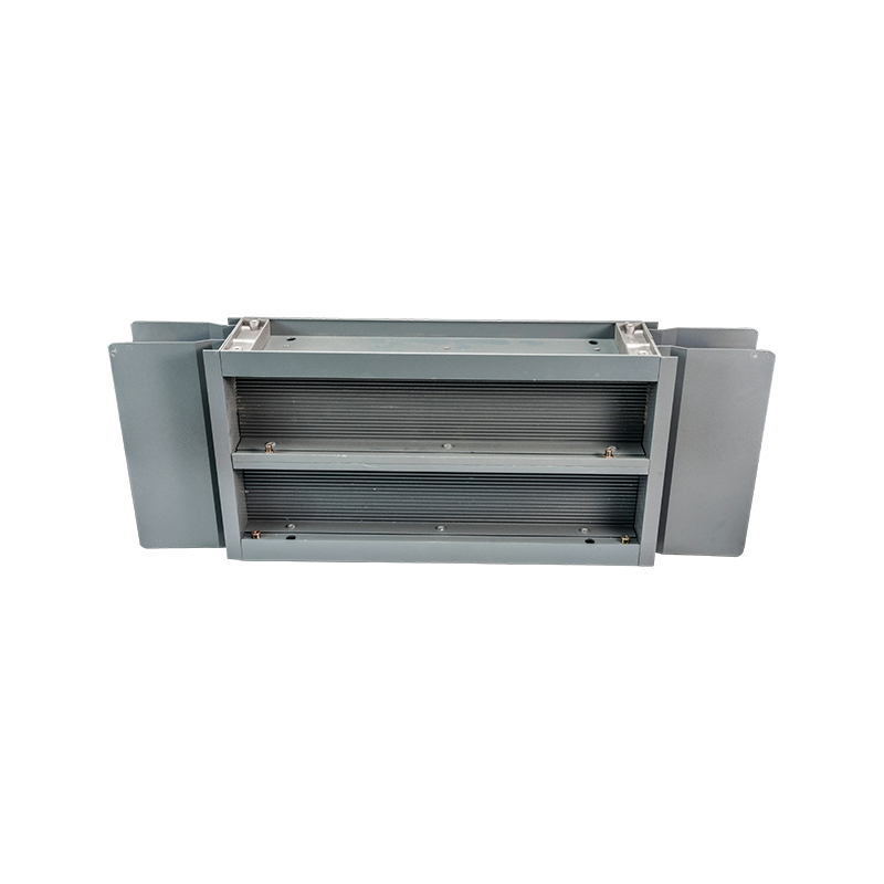
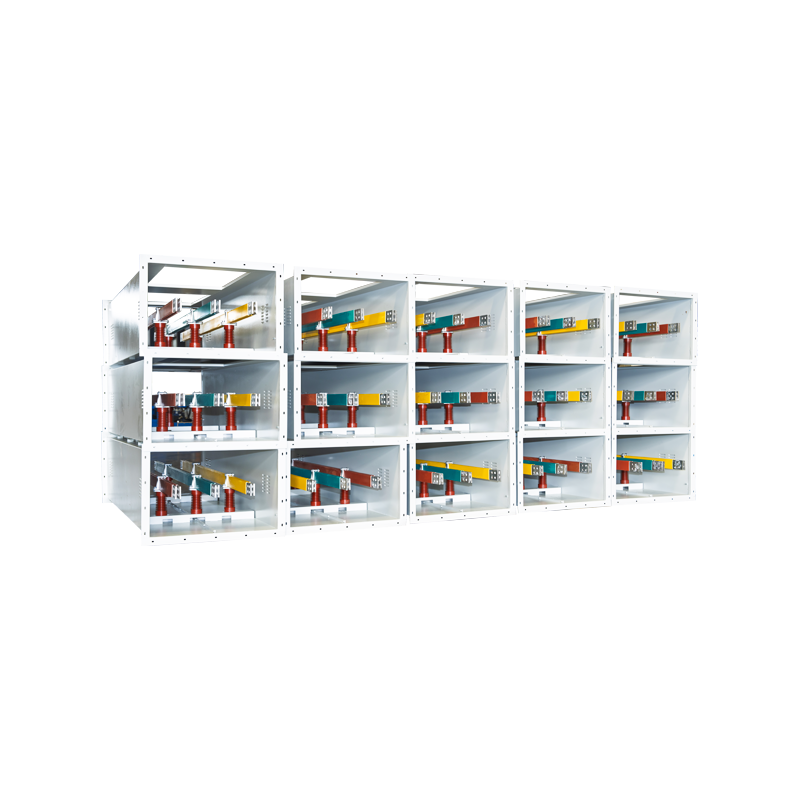


Post Insulators for Reliable Tubular Busbar and Power Distribution Systems
Content
- 1 1. What Is a Post Insulator?
- 2 2. The Role of Post Insulators in Tubular Busbar Systems
- 3 3. Main Advantages Compared with Conventional Busbar Arrangements
- 4 4. Materials Used for Post Insulators
- 5 5. Environmental Adaptability
- 6 6. Seismic and Vibration Performance
- 7 7. Manufacturing Processes and Quality Control
- 8 8. Engineering Strengths of the Manufacturer
- 9 9. Applications
- 10 10. Selection Guide
- 11 11. Installation and Maintenance Recommendations
- 12 12. Frequently Asked Questions
- 12.1 Q1: What is the main purpose of a post insulator?
- 12.2 Q2: Can an insulated tubular busbar eliminate post insulators?
- 12.3 Q3: What is the maximum span of the described tubular busbar?
- 12.4 Q4: What materials are available for post insulators?
- 12.5 Q5: Are composite post insulators suitable for polluted areas?
- 12.6 Q6: What pollution level can the system withstand?
- 12.7 Q7: Can the system operate at high altitude?
- 12.8 Q8: How long can a post insulator last?
- 12.9 Q9: What mechanical load can a post insulator withstand?
- 12.10 Q10: What tests should be requested from a manufacturer?
- 13 13. Why Choose an Integrated Tubular Busbar Solution?
- 14 14. Conclusion
- 15 References
- 16 Product: Post Insulator
Post insulators are essential mechanical and electrical components in many power distribution, substation, switchgear, and busbar applications. They support energized conductors, maintain the required clearance from grounded structures, withstand mechanical forces, and prevent current leakage between live parts and earth. In modern tubular busbar systems, their role is becoming more specialized because the busbar structure itself can provide greater mechanical strength, longer support spans, and simplified installation.
A well-designed insulated tubular busbar system may reduce or even eliminate the need for conventional post insulators in selected sections. Instead of relying on multiple separate insulators, fittings, wall bushings, and supporting foundations, the tubular busbar can be fixed directly to steel structures or concrete supports through dedicated brackets. This integrated approach improves structural efficiency, reduces installation complexity, and minimizes the number of potential failure points.
However, post insulators remain important wherever independent electrical insulation and mechanical support are required. They are used in substations, medium- and high-voltage switchgear, industrial power systems, transformer stations, renewable energy facilities, and distribution cabinets. The appropriate solution depends on voltage level, short-circuit current, span length, environmental pollution, seismic conditions, installation method, and required mechanical strength.
Jiangsu Wopeng Power Technology Co., Ltd. develops and manufactures high- and low-voltage busbar systems, including aluminum alloy tubular busbars, copper and aluminum tube busbars, epoxy resin vacuum-cast tube busbars, low-voltage cast-resin busways, wind power tubular busbars, compact busbar systems, and sliding contact line systems. Its engineering capability allows post insulators and tubular busbar structures to be evaluated as part of a complete power transmission solution rather than as isolated components.
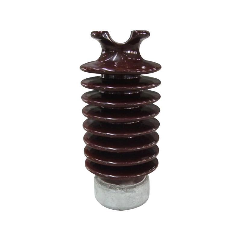
Post Insulator
1. What Is a Post Insulator?
A post insulator is a rigid insulating component designed to support an energized conductor, busbar, cable termination, or electrical apparatus while maintaining electrical isolation from the supporting structure. Unlike suspension insulators, which are generally used in strings or flexible hanging arrangements, post insulators provide a fixed and stable support point.
In a typical installation, the post insulator is mounted on a steel frame, concrete foundation, switchgear panel, or other grounded structure. The conductor or busbar is fixed to the upper portion of the insulator. The insulating body separates the energized part from the grounded mounting surface and provides the required creepage distance and air clearance.
Post insulators must perform two functions simultaneously. First, they must withstand the normal operating voltage and temporary overvoltages without flashover or puncture. Second, they must resist mechanical loads generated by conductor weight, wind, thermal expansion, vibration, short-circuit forces, and seismic movement.
For this reason, post insulators are selected according to both electrical and mechanical parameters. A product with an adequate voltage rating but insufficient bending strength may fail under short-circuit conditions. Conversely, a mechanically strong component with inadequate creepage distance may experience surface flashover in polluted or humid environments.
1.1 Electrical Isolation
The primary electrical function of a post insulator is to prevent current from flowing between an energized conductor and a grounded support. The insulating material must possess high dielectric strength and stable insulation resistance over the expected service life.
Electrical insulation performance is affected by operating voltage, transient overvoltage, surface contamination, humidity, altitude, temperature, and the shape of the insulating sheds. In outdoor installations, dust, salt, industrial chemicals, and moisture can form a conductive film on the surface. The design must therefore provide sufficient creepage distance and an effective shed profile.
The creepage distance is the shortest path along the surface of the insulator between two conductive points. A longer creepage distance generally improves resistance to surface leakage and pollution flashover. For heavily polluted environments, the design may include additional sheds or creepage extenders, especially at outdoor terminals.
1.2 Mechanical Support
Post insulators also act as structural supports. They carry the weight of the busbar and connected fittings while resisting horizontal and vertical forces. During a short circuit, the electromagnetic force between adjacent conductors can increase rapidly. The supporting insulator, mounting hardware, and busbar must work together to withstand this dynamic load.
Mechanical performance is commonly evaluated through bending strength, cantilever load, tensile strength, compression strength, and impact resistance. The required rating depends on busbar size, phase spacing, support spacing, short-circuit current, and installation configuration.
In conventional rectangular busbar systems, support spacing is often relatively short because the conductors have limited bending stiffness and are more sensitive to electromagnetic forces. Tubular busbars provide a different structural solution. Their circular cross-section offers a favorable strength-to-weight ratio and allows longer spans with fewer support points.
2. The Role of Post Insulators in Tubular Busbar Systems
Tubular busbars are used to transmit high currents in substations, power plants, industrial plants, renewable energy stations, and other high-demand electrical installations. The busbar may be made from copper or aluminum alloy and may be bare, insulated, epoxy cast, or otherwise enclosed depending on the system design.
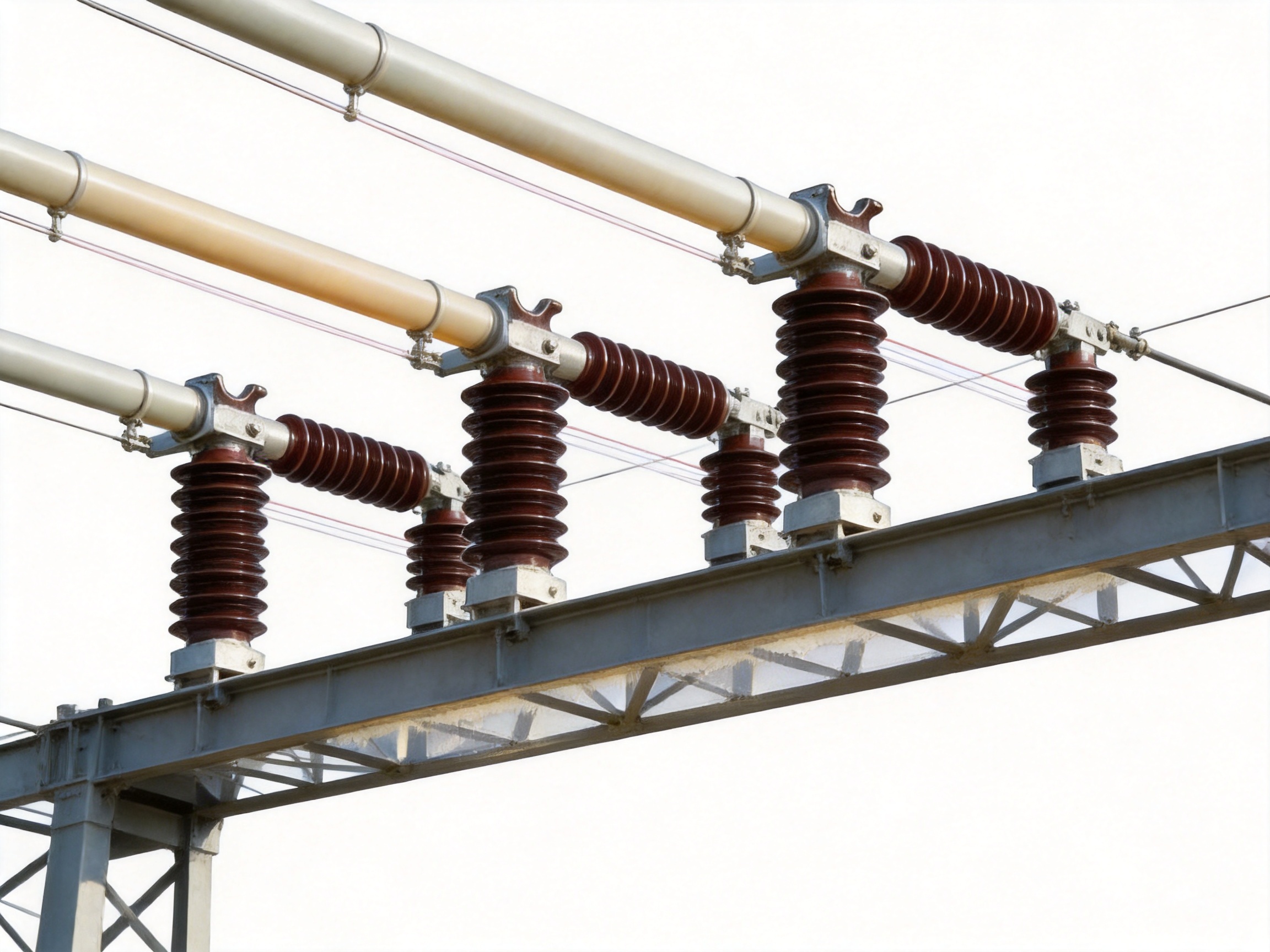
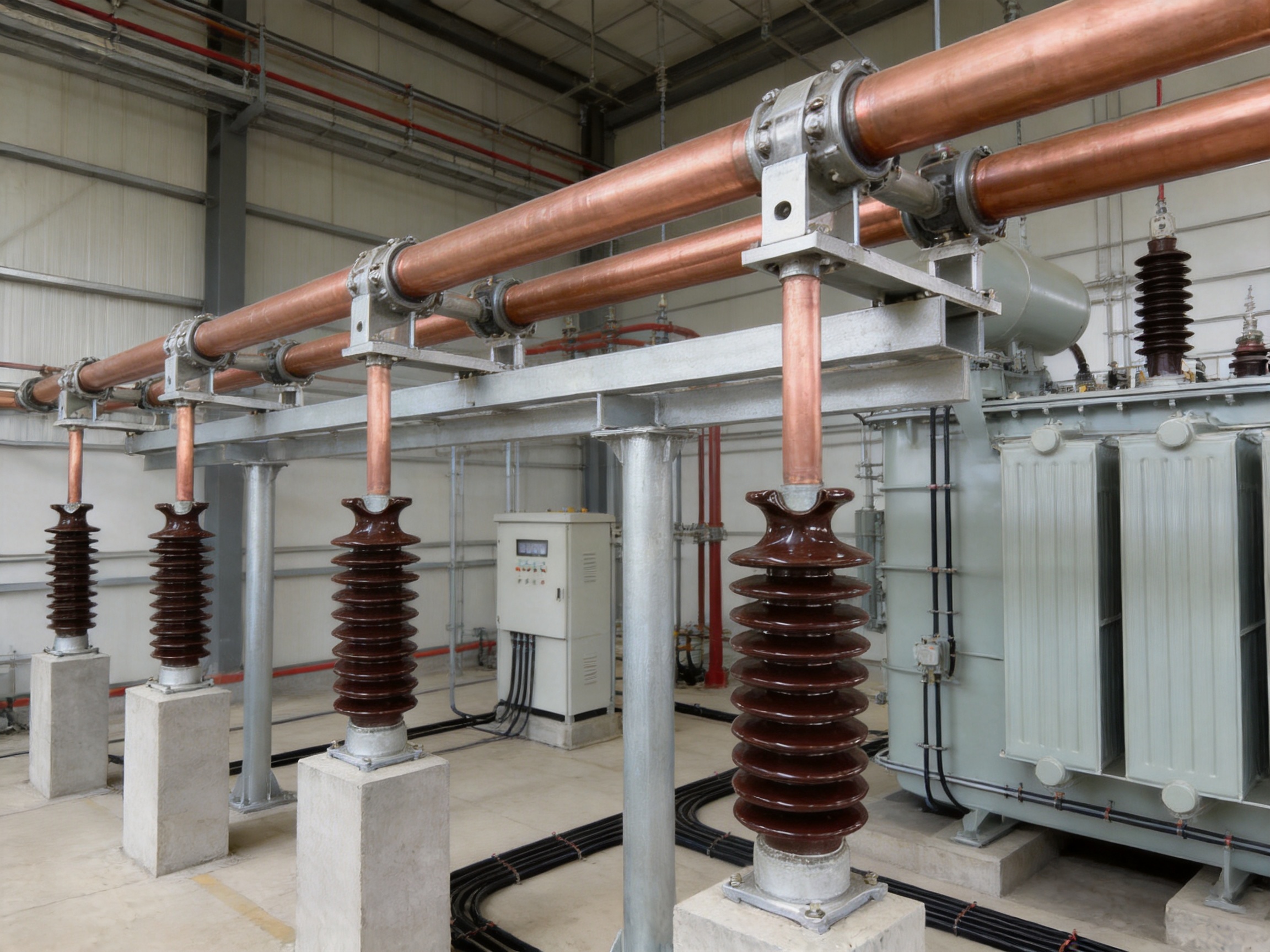
In a traditional arrangement, post insulators support the busbar at regular intervals. Each support point requires mechanical hardware, mounting plates, and sometimes a dedicated concrete or steel foundation. The number of components increases with the length of the busbar and the required short-circuit withstand level.
An insulated tubular busbar can simplify this arrangement. Because the tube has high mechanical stiffness and an integrated insulating outer layer, it may be directly fixed to steel structures or concrete supports using specially designed brackets. The supporting structure can replace some of the functions traditionally provided by post insulators and separate busbar fittings.
This does not mean that post insulators are unsuitable for tubular busbars. Rather, their use becomes application-dependent. Post insulators may still be required at transition points, terminal connections, equipment interfaces, expansion sections, vertical risers, or areas where electrical separation from the supporting structure must be independently maintained.
The most efficient design evaluates the complete current path, support structure, insulation system, and installation environment. In some sections, direct bracket support may be preferable. In other sections, a high-strength post insulator may provide the most reliable solution. A professional manufacturer should be able to offer both approaches and explain the engineering basis for the selection.
2.1 Direct Fixing and Structural Simplification
One of the main advantages of an insulated tubular busbar is the possibility of direct fixing to structural steel or concrete supports. This approach can eliminate wall bushings and reduce the number of conventional post insulators required between equipment and busbar sections.
The result is a more compact system with fewer separate components. Fewer components can reduce assembly time, simplify alignment, and lower the probability of loose connections or installation errors. It may also reduce the quantity of steelwork, foundation construction, and maintenance access required by the project.
Dedicated tubular busbar brackets are used to maintain the designed position and clearance. The recommended bracket spacing in the described system is not less than 275 millimeters where applicable to the exposed installation arrangement. Fixed brackets are required for spans from 6 meters to 13 meters to control movement and maintain alignment.
2.2 Mechanical Strength and Span Capability
The allowable stress of an insulated tubular busbar can be approximately four times that of a comparable rectangular busbar design, depending on the material, dimensions, and engineering conditions. This high mechanical efficiency allows the system to withstand substantial short-circuit forces while using fewer supports.
Under a short-circuit current of 50 kA, a tubular busbar with a diameter of 100 millimeters and a wall thickness of 6 millimeters can achieve a suspended span of up to 9 meters in the specified design conditions. When supported by dedicated busbar brackets, the span may reach 13 meters.
Longer support spans provide several practical benefits. They reduce the number of foundations, insulators, brackets, and connection points. They can also create more open equipment layouts, improve access for inspection, and simplify the routing of busbars across large electrical rooms or outdoor substation structures.
Actual span capability must always be confirmed through engineering calculation. Factors such as conductor weight, thermal expansion, wind load, seismic acceleration, phase spacing, short-circuit peak current, support stiffness, and connection geometry affect the final design.
3. Main Advantages Compared with Conventional Busbar Arrangements
3.1 Reduced Number of Components
Conventional busbar systems often require numerous post insulators, support plates, wall bushings, clamps, fittings, and structural foundations. Each component adds to the bill of materials and requires inspection during installation.
An insulated tubular busbar system can integrate mechanical support, electrical insulation, and current transmission into a more compact structure. Direct fixing to steel or concrete supports reduces dependence on separate post insulators in suitable sections. This can reduce material consumption and shorten the installation schedule.
Fewer components also improve system consistency. When many individual supports are installed, small alignment differences can accumulate along a long busbar route. A standardized tubular bracket arrangement provides a more controlled installation method and supports repeatable manufacturing and site assembly.
3.2 Longer Support Spans
The circular geometry of a tubular busbar offers high resistance to bending. Compared with a flat rectangular conductor of similar material volume, a tube can provide improved stiffness and a more balanced response to forces from multiple directions.
The longer support span reduces the number of intermediate support points. This is particularly useful in power plants, substations, wind power installations, and industrial facilities where busbars must cross wide equipment areas or connect separate rooms.
Long spans can also reduce visual obstruction and improve working space around the electrical equipment. The design may require fewer structural foundations, which is valuable where construction space is limited or where the site has difficult soil conditions.
3.3 Strong Short-Circuit Performance
Short-circuit current produces considerable electromagnetic force between adjacent phases. The force can cause conductor movement, deformation, support damage, or connection failure if the busbar system is not properly designed.
The high stiffness of a tubular busbar helps control deformation during a fault. The insulated tubular construction also provides a protected external surface that can reduce the risk of accidental contact and contamination of the conductor. When combined with correctly rated brackets and connection hardware, the system can maintain its position during severe fault conditions.
The specified design is intended to operate under a short-circuit current of 50 kA in defined configurations. This performance is not solely a property of the tube. It depends on the complete system, including phase arrangement, support spacing, bracket strength, joint design, enclosure or insulation, and foundation stiffness.
3.4 Simplified Connection to Electrical Equipment
The tubular busbar can be directly connected to high-voltage rooms, indoor current-limiting reactors, and 10 kV switchgear cabinets. Direct connection reduces the transition pieces and support assemblies traditionally used between the busbar and the equipment.
A simplified transition can reduce voltage stress concentration and mechanical discontinuities. It may also reduce the physical footprint of the equipment connection area. This is beneficial in compact substations, indoor switchgear rooms, and industrial plants where available floor space is limited.
Connection design must account for thermal expansion, equipment vibration, terminal tolerances, and maintenance requirements. Flexible connectors, expansion joints, or specially designed terminal structures may be required to avoid excessive force on the equipment bushing or switchgear terminal.
3.5 Lower Maintenance Requirements
Traditional exposed post insulators require periodic inspection for contamination, cracks, chips, surface erosion, loose hardware, and signs of flashover. In locations with heavy pollution, cleaning may be required at regular intervals.
Insulated tubular busbars reduce the exposed conductive area and can provide a more enclosed current path. This reduces the amount of contamination that reaches the live conductor and lowers the frequency of cleaning and corrective maintenance.
Maintenance is not eliminated completely. Operators should still inspect brackets, joints, terminal areas, insulation surfaces, grounding arrangements, and signs of overheating. However, the integrated structure can reduce the number of individual components that need routine inspection.
4. Materials Used for Post Insulators
4.1 Electrical Porcelain
Electrical porcelain has been used for post insulators for many decades. It offers high compressive strength, good resistance to ultraviolet radiation, and stable performance across a broad temperature range. Porcelain is suitable for many indoor and outdoor medium- and high-voltage applications.
Its disadvantages include relatively high weight and susceptibility to brittle fracture under severe mechanical impact. A damaged porcelain insulator may show visible cracks, but small defects can still require careful inspection. Transport and installation must be managed to prevent chipping or impact damage.
4.2 Toughened Glass
Toughened glass provides high dielectric performance and a smooth surface that can be easier to inspect. When failure occurs, the material may break into small pieces rather than forming large sharp fragments. However, glass post insulators are less common than porcelain or composite designs in certain fixed-support applications.
4.3 Composite Materials
Composite post insulators generally use a fiberglass-reinforced polymer core covered by a silicone rubber or other polymer housing. They are lightweight, resistant to impact, and suitable for installations where handling weight is a major consideration.
Silicone rubber provides hydrophobicity, meaning that water tends to form droplets rather than a continuous conductive film. This property can improve pollution performance and reduce the probability of surface flashover in coastal, industrial, or high-humidity environments.
Composite materials also offer good resistance to burst failure and can be manufactured in different shapes and mechanical ratings. Their long-term performance depends on housing quality, interface design, sealing, material formulation, and resistance to aging caused by ultraviolet radiation, heat, and pollution.
| Material | Typical Voltage Application | Mechanical Characteristics | Environmental Performance | Key Considerations |
|---|---|---|---|---|
| Electrical porcelain | Low voltage to very high voltage | High compressive strength and stable rigidity | Excellent weather resistance | Heavy and comparatively brittle |
| Toughened glass | Medium and high voltage applications | Good mechanical stability | Good weather resistance and easy visual inspection | Specific designs may be less common for tubular busbar support |
| Polymer or silicone rubber composite | Low voltage to high voltage | Lightweight, high bending strength, good impact resistance | Strong hydrophobicity and good pollution performance | Requires controlled material and interface quality |
| Epoxy resin cast insulation | Medium voltage and enclosed busbar systems | Rigid, compact, and highly integrated | Good protection from moisture and contamination | Manufacturing quality and thermal design are critical |
5. Environmental Adaptability
Power transmission equipment is often installed in severe environments. Coastal areas may expose insulators to salt deposits, while industrial facilities may produce conductive dust, chemical vapors, or oily contamination. High-altitude locations have reduced air density, which affects external insulation performance.
5.1 Pollution Severity
The described post insulator and tubular busbar solutions are designed for environments with pollution severity up to Class V, or heavy pollution, when the correct configuration is selected. The design creepage distance ratio is 31 millimeters per kilovolt.
For outdoor terminals, creepage extenders may be installed to increase the total creepage distance. After installation of the specified extenders, the total creepage distance is not less than 680 millimeters in the stated design.
Pollution performance depends on more than creepage distance. Shed spacing, shed depth, material hydrophobicity, surface profile, water-shedding behavior, and local climate all influence flashover resistance. The product should therefore be selected using site-specific environmental data rather than voltage rating alone.
5.2 High-Altitude Operation
The system is suitable for altitudes up to 4,000 meters under the stated application conditions. At high altitude, the lower air density reduces the dielectric strength of air. Clearances that are adequate at sea level may require correction at elevated locations.
High-altitude design should consider both external insulation and equipment cooling. Air insulation, heat dissipation, corona behavior, and temperature rise can all be affected. The manufacturer should confirm the applicable altitude correction factors during technical review.
5.3 Temperature and Moisture
Daily and seasonal temperature changes cause thermal expansion and contraction of the conductor, insulation, brackets, and connected equipment. A rigid system must include suitable allowance for thermal movement so that excessive stress is not transferred to terminals or supports.
Moisture can affect surface insulation, metal corrosion, and the performance of joints. Proper sealing, drainage, surface treatment, and material selection are important for outdoor equipment and installations exposed to condensation.
6. Seismic and Vibration Performance
Power equipment installed in seismic regions must remain mechanically stable during ground movement. Failure of a busbar support can create phase-to-phase faults, damage connected equipment, and cause extended outages.
The described design considers a horizontal acceleration of 0.20 g, a vertical acceleration of 0.15 g, and a vibration frequency of 20 Hz. It tolerates three sine-wave cycles under the specified seismic test conditions, with a safety factor greater than 1.67.
These requirements are intended to ensure normal operation under simultaneous seismic and short-circuit conditions. The performance of the complete installation depends on the connection between the busbar, post insulator, bracket, steel structure, and foundation. A strong insulator cannot compensate for an inadequately designed support frame.
Seismic design should verify the natural frequency of the busbar assembly, resonance risk, bolt preload, bracket deformation, foundation strength, and relative movement between connected equipment. Flexible connections may be required where separate structures move differently during an earthquake.
7. Manufacturing Processes and Quality Control
The reliability of a post insulator or insulated tubular busbar depends heavily on manufacturing consistency. Electrical insulation systems operate under high voltage for many years, often in locations where maintenance and replacement are difficult. Small defects in casting, bonding, machining, or assembly can become serious problems after extended service.
7.1 Material Control
Manufacturing begins with the selection and inspection of raw materials. Aluminum alloy tubes must meet specified chemical composition, dimensional tolerance, surface quality, and mechanical requirements. Copper conductors require control of conductivity, purity, hardness, and dimensional stability.
For composite post insulators, the fiberglass-reinforced core, silicone rubber housing, end fittings, and bonding materials must be compatible. For epoxy resin busbars, resin formulation, filler distribution, curing behavior, and thermal properties must be controlled.
Incoming materials should be verified through supplier documentation, sampling inspection, dimensional checks, and, where necessary, laboratory testing. Traceability allows production personnel to identify the material batch used in each product.
7.2 CNC Machining
CNC machining is used to manufacture precision end fittings, connection components, support interfaces, terminal parts, and other metal hardware. Accurate machining ensures correct alignment between the busbar, insulator, bracket, and equipment terminal.
Dimensional accuracy is particularly important for long tubular busbar assemblies. Small errors in flange position or fitting geometry can create misalignment over a long route. CNC processing helps maintain repeatability and reduces dependence on manual correction during site installation.
Machined components are inspected for dimensions, surface finish, thread quality, hole position, and interface flatness. Proper surface treatment may include cleaning, anodizing, galvanizing, painting, or other corrosion-protection processes according to the material and service environment.
7.3 Vacuum Casting
Vacuum casting is used for epoxy resin vacuum-cast tube busbars and other integrated insulation products. The process removes air and reduces the risk of voids inside the insulating material. Voids, cracks, and interface defects can create localized electric-field concentration and reduce dielectric strength.
During vacuum casting, the conductor and mold are prepared according to a controlled process. Resin and hardener are mixed in a specified ratio, degassed, injected under vacuum or controlled pressure, and cured according to the required temperature and time profile.
Process parameters must be monitored and recorded. These may include resin temperature, mold temperature, vacuum level, filling time, curing temperature, and post-curing conditions. Consistent control improves insulation uniformity and reduces the risk of partial discharge.
7.4 Automated Assembly
Automated or standardized assembly improves repeatability in the installation of fittings, insulation components, brackets, connectors, and protective parts. Controlled torque procedures help ensure that bolted joints are secure without damaging insulation or deforming metal components.
Assembly personnel should follow defined work instructions for conductor preparation, surface cleaning, alignment, sealing, fastening, and final inspection. Where adhesive or bonding systems are used, humidity, temperature, surface preparation, and curing time should be controlled.
7.5 Electrical Testing
Each product should undergo suitable routine tests before shipment. These may include insulation resistance testing, power-frequency withstand testing, partial discharge testing, dimensional inspection, conductor resistance measurement, and visual examination.
High-voltage testing verifies that the insulation can withstand the specified voltage without breakdown or flashover. Insulation resistance testing identifies leakage paths or contamination. Partial discharge testing can reveal internal voids, cracks, or defects that may not be visible during a routine visual inspection.
For post insulators and busbar support systems, mechanical verification may include bending load testing, load-deflection measurement, fitting inspection, and torque verification. Type tests may be performed to validate short-circuit withstand, temperature rise, seismic performance, environmental resistance, and other application-specific requirements.
8. Engineering Strengths of the Manufacturer
Jiangsu Wopeng Power Technology Co., Ltd. was founded in 2018 as a specialized high-tech enterprise focused on high- and low-voltage busbar systems. Its product range covers applications from low voltage to 35 kV and includes both conventional and integrated tubular busbar technologies.
The company combines engineering design, material selection, machining, casting, assembly, testing, and technical support. This integrated capability is important for projects that require customized busbar dimensions, unusual support spans, special terminal arrangements, or operation in difficult environments.
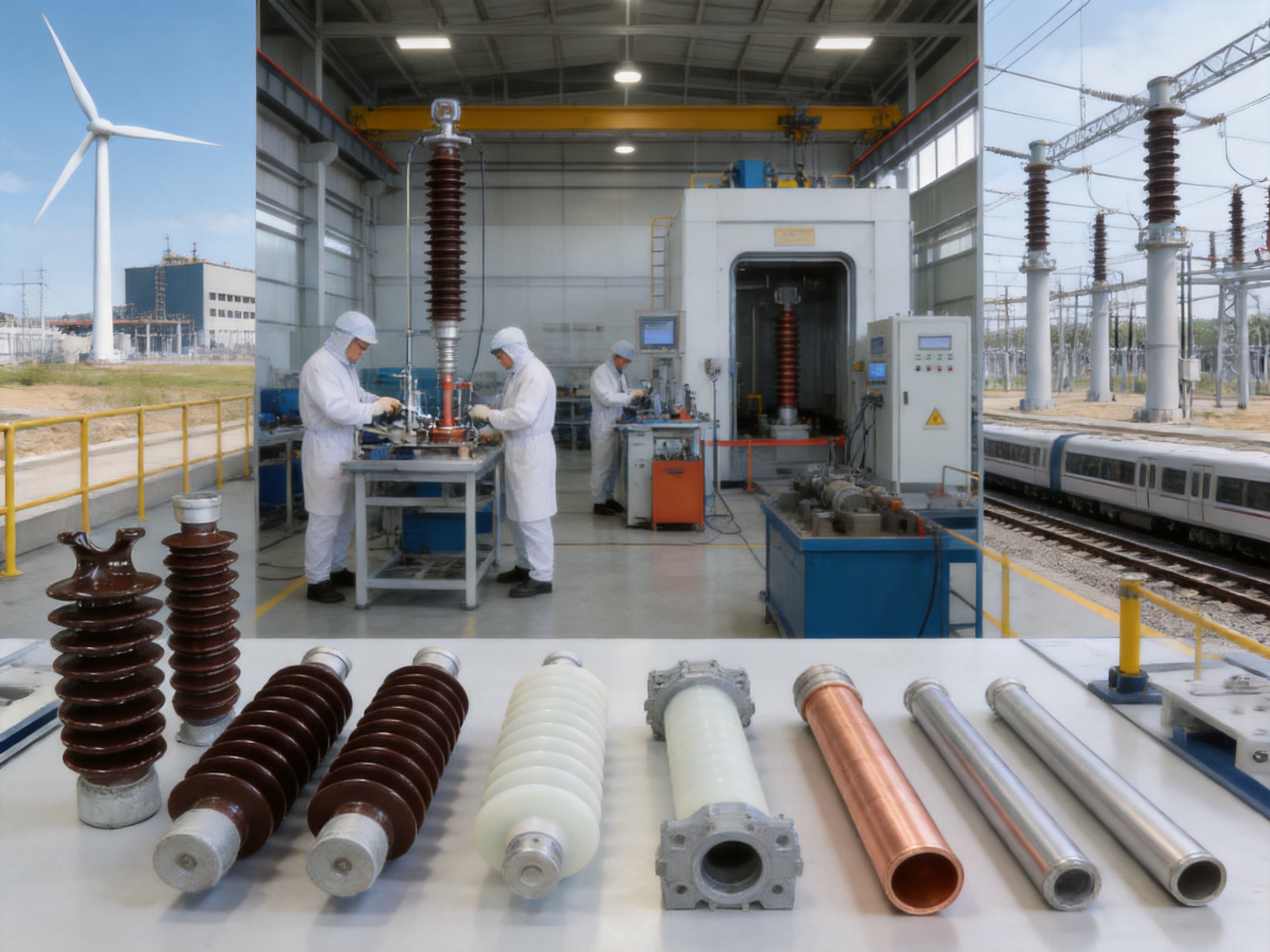
Its manufacturing resources include vacuum casting systems, CNC machining equipment, and automated assembly technologies. These facilities support production of epoxy resin vacuum-cast tubular busbars, aluminum and copper tube busbars, low-voltage cast-resin busways, compact busbar systems, and wind power tubular busbars.
The company’s products are used in power generation, substations, wind energy, industrial manufacturing, rail transit, and large commercial facilities. Its systems operate across more than 17 provinces and serve applications requiring stable current transmission, compact installation, high mechanical strength, and dependable insulation.
A further strength is the ability to design a complete system rather than supply a standard insulator without considering the surrounding equipment. Engineering evaluation can include busbar cross-section, material, phase arrangement, support spacing, fault current, insulation level, creepage distance, seismic conditions, altitude, and connection method.
Testing collaboration with third-party institutions provides additional independent validation for selected products and applications. Third-party testing is valuable for confirming safety, electrical performance, mechanical strength, and compliance with project specifications.
9. Applications
9.1 Substations
Post insulators and tubular busbars are widely used in indoor and outdoor substations. They support bus sections, connect transformers and switchgear, and provide high-current paths between major pieces of equipment.
In outdoor substations, pollution, rain, ultraviolet exposure, wind, and temperature changes must be considered. In indoor substations, space limitations, ventilation, fire safety, and connection flexibility may be more important.
9.2 Power Plants
Power generation facilities require reliable high-current connections between generators, transformers, switchgear, and auxiliary systems. Tubular busbars can provide high mechanical strength and a compact layout in generator connection areas and plant substations.
The reduction of support points can simplify routing through large equipment halls. The system may also reduce maintenance requirements in locations where access to elevated busbars is difficult.
9.3 Wind Power Installations
Wind turbines experience continuous vibration, changing loads, and restricted installation space. Tubular busbars designed for wind power applications must tolerate mechanical movement, temperature variation, and high current transmission.
Lightweight aluminum alloy structures can reduce handling difficulty, while high-strength tubular geometry helps maintain structural stability. Connection design is especially important because equipment inside a nacelle may experience movement relative to the tower and transformer system.
9.4 Industrial Facilities
Steel mills, chemical plants, manufacturing facilities, and large processing plants often require high-current busbar systems between transformers, distribution boards, motors, and process equipment.
Industrial pollution may include dust, moisture, chemical vapors, and conductive particles. An insulated tubular system reduces exposure of the conductor and can be configured with suitable creepage distances and protective materials for the site.
9.5 Rail Transit and Commercial Infrastructure
Rail transit systems and large commercial buildings require compact, dependable electrical distribution. Space restrictions may make long-span busbar structures attractive. Reduced foundations and simplified support arrangements can also help coordinate electrical installation with architectural and civil construction work.
10. Selection Guide
Selecting a post insulator or tubular busbar support should begin with the electrical requirements. Confirm the rated voltage, maximum system voltage, power-frequency withstand level, lightning impulse withstand level, rated current, and short-circuit current.
The mechanical requirements should then be evaluated. These include conductor weight, span length, wind load, seismic acceleration, thermal movement, cantilever force, vertical load, and equipment connection stress. The support structure should be included in the calculation.
Environmental conditions are equally important. Specify altitude, ambient temperature, humidity, pollution severity, salt exposure, ultraviolet radiation, chemical contamination, and indoor or outdoor installation. For heavy pollution, request the required creepage distance and confirm whether creepage extenders are needed.
Material selection depends on the installation objective. Porcelain may be selected for proven outdoor performance and high rigidity. Composite materials may be preferred for reduced weight and improved hydrophobicity. Epoxy resin cast insulation may be selected for compact, integrated, and enclosed tubular busbar systems.
Finally, review the manufacturer’s technical documentation. Important documents may include product drawings, material certificates, routine test reports, type test reports, installation instructions, inspection records, and maintenance recommendations.
11. Installation and Maintenance Recommendations
11.1 Installation
Before installation, verify the foundation, steel structure, bracket position, busbar dimensions, phase spacing, and connection interfaces. The support structure must be level and sufficiently rigid. Incorrect alignment can create stress in the busbar and connected equipment.
During installation, avoid impact, sharp bending, contamination, and unauthorized drilling or cutting of insulated components. Metal surfaces should be cleaned before connection, and contact surfaces should be treated according to the manufacturer’s instructions.
Bolted connections should be tightened to the specified torque. Excessive torque may damage fittings or insulation, while insufficient torque may cause heating, vibration, and loosening. Where thermal expansion is expected, expansion joints or flexible connectors should be installed as designed.
For exposed tubular busbar installations, dedicated brackets should be used. Bracket spacing should meet the approved engineering design, with the stated arrangement using spacing of at least 275 millimeters where applicable. Fixed brackets should be installed for spans from 6 meters to 13 meters.
11.2 Commissioning
Commissioning should include visual inspection, insulation resistance measurement, high-voltage testing where specified, continuity checks, grounding verification, and inspection of all mechanical connections.
Thermal imaging under load can help identify abnormal heating at joints and terminals. Any temperature difference between similar phases or connections should be investigated before the system is placed into continuous service.
11.3 Routine Maintenance
Routine maintenance should include inspection for surface contamination, cracks, corrosion, loose bolts, damaged insulation, abnormal vibration, and signs of electrical tracking. Outdoor terminals should be checked for the condition of creepage extenders and weatherproof seals.
Maintenance intervals should be based on the operating environment. Heavy pollution, high humidity, coastal salt, and frequent short-circuit events may require more frequent inspections. Records should be maintained so that changes in temperature, insulation resistance, vibration, and appearance can be monitored over time.
12. Frequently Asked Questions
Q1: What is the main purpose of a post insulator?
A post insulator supports an energized conductor or busbar while electrically isolating it from grounded structures. It also withstands mechanical forces caused by conductor weight, short-circuit current, wind, vibration, and seismic movement.
Q2: Can an insulated tubular busbar eliminate post insulators?
In selected sections, an insulated tubular busbar can be fixed directly to steel structures or concrete supports, reducing or eliminating conventional post insulators. The final arrangement depends on the voltage level, insulation design, support structure, connection point, and applicable engineering requirements.
Q3: What is the maximum span of the described tubular busbar?
Under a short-circuit current of 50 kA, a Φ100 × 6 mm tubular busbar can achieve a suspended span of up to 9 meters in the specified conditions. With dedicated busbar bracket support, the span can reach up to 13 meters. Actual project values must be verified by calculation.
Q4: What materials are available for post insulators?
Common materials include electrical porcelain, toughened glass, silicone rubber composite materials, and epoxy resin systems. The best choice depends on voltage, mechanical load, pollution, weight, outdoor exposure, and the required design life.
Q5: Are composite post insulators suitable for polluted areas?
Yes. Silicone rubber composite post insulators offer hydrophobicity and good resistance to pollution flashover. They can be suitable for coastal, industrial, and humid environments when the creepage distance and material quality meet the application requirements.
Q6: What pollution level can the system withstand?
The described design is suitable for pollution severity up to Class V under the stated conditions. The creepage distance ratio is 31 millimeters per kilovolt, and outdoor terminals can use creepage extenders to achieve a total creepage distance of at least 680 millimeters.
Q7: Can the system operate at high altitude?
The stated system is suitable for altitudes up to 4,000 meters. High-altitude projects should still be reviewed for air-clearance correction, dielectric strength, temperature rise, cooling, and applicable design standards.
Q8: How long can a post insulator last?
A high-quality post insulator may provide approximately 20 to 40 years of service under normal operating conditions. Actual life depends on electrical stress, mechanical loading, pollution, ultraviolet exposure, moisture, temperature, installation quality, and maintenance.
Q9: What mechanical load can a post insulator withstand?
Standard designs may withstand bending loads from approximately 2 kN to 20 kN, depending on size, material, construction, and rating. The required load rating must be calculated from the busbar geometry and operating conditions.
Q10: What tests should be requested from a manufacturer?
Customers should request relevant routine and type test documents, including insulation resistance, power-frequency withstand, partial discharge where applicable, temperature rise, mechanical load, short-circuit withstand, seismic performance, and dimensional inspection records.
13. Why Choose an Integrated Tubular Busbar Solution?
The main competitive advantage of an integrated tubular busbar solution is that it addresses current transmission, insulation, mechanical support, and installation efficiency together. Conventional systems may require several independent components to perform these functions. A tubular system can combine them into a more compact and structurally efficient assembly.
The higher allowable stress and longer support span reduce the number of support points. Direct connection to high-voltage rooms, current-limiting reactors, and 10 kV switchgear cabinets can reduce transition hardware. Exposed installation with dedicated brackets can simplify construction, while insulated surfaces reduce contamination exposure.
The system is also adaptable. Copper and aluminum alloy conductors can be selected according to conductivity, weight, cost, thermal performance, and mechanical requirements. Epoxy resin vacuum casting can provide an integrated insulation structure for medium-voltage applications. Composite post insulators can be used where lightweight, hydrophobic, and high-strength independent support is required.
Jiangsu Wopeng Power Technology Co., Ltd. supports this product strategy through engineering design, controlled material processing, vacuum casting, CNC machining, automated assembly, electrical testing, and third-party testing cooperation. This manufacturing depth helps ensure that the product is not simply a standard component, but a solution adapted to the project’s electrical and mechanical conditions.
14. Conclusion
Post insulators remain a fundamental part of power system construction because they provide both electrical isolation and mechanical support. Their performance directly affects the safety, stability, and service life of substations, switchgear, distribution equipment, and busbar systems.
At the same time, insulated tubular busbars provide an advanced alternative to heavily segmented conventional busbar arrangements. Their high mechanical strength, long support spans, integrated insulation, reduced component count, and direct connection capability can lower installation complexity and maintenance requirements.
The best solution is not determined by the name of a single component. It is determined by a complete evaluation of voltage, current, fault level, span, environment, altitude, seismic conditions, connection geometry, and maintenance strategy. In some locations, post insulators remain essential. In others, direct tubular busbar support offers a more efficient structure.
With experience in aluminum and copper tubular busbars, epoxy resin vacuum-cast systems, low-voltage busways, wind power applications, compact busbars, and sliding contact line systems, Jiangsu Wopeng Power Technology Co., Ltd. is positioned to provide customized power transmission solutions for demanding industrial and infrastructure projects.
References
1. IEC 60168, Tests on Indoor and Outdoor Post Insulators of Ceramic Material or Glass for Systems with Nominal Voltages Greater Than 1,000 V.
2. IEC 62271 Series, High-Voltage Switchgear and Controlgear.
3. IEC 60865-1, Short-Circuit Currents: Calculation of Effects.
4. IEC 60071 Series, Insulation Coordination.
5. IEC 61109, Composite Insulators for AC Overhead Lines and Substations.
6. IEEE Standard 693, Recommended Practice for Seismic Design of Substations.
7. IEEE Standard 4, Standard for High-Voltage Testing Techniques.
8. CIGRE Technical Publications on Substation Busbar Design, Short-Circuit Forces, and Outdoor Insulation Performance.
9. Manufacturer technical documentation for insulated tubular busbar systems, aluminum alloy tubular busbars, post insulators, and epoxy resin vacuum-cast busbars.
10. Manufacturer quality-control records covering high-voltage testing, insulation testing, mechanical verification, dimensional inspection, and routine production checks.
Product: Post Insulator



-
 +86-180 3625 3000
-
 admin@wpbusbar.com
-
 No. 8, Yanjin Road, Chengxi Industrial Park, Shanyang Town, Baoying County, Yangzhou City, Jiangsu Province, China
Copyright © Jiangsu Wopeng Power Technology Co., Ltd.
All Rights Reserved.
 Custom Insulated Bus Bar Manufacturer
Tubular Busbar System Factory
Custom Insulated Bus Bar Manufacturer
Tubular Busbar System Factory