

 EN
EN

 English
 русский
 Français
 Español
 عربى
عربى


Ultra-High Voltage Magnesium-Aluminum Alloy Tubular Bus Bar: Design, Performance, and Manufacturing Advantages
Content
- 1 1. The Role of Tubular Bus Bars in Ultra-High Voltage Systems
- 2 2. Product Composition and Alloy Options
- 3 3. Structural Design of the Tubular Conductor
- 4 4. Main Technical Advantages
- 4.1 4.1 High Electrical Conductivity
- 4.2 4.2 High Current-Carrying Capacity
- 4.3 4.3 Low Weight and Reduced Structural Loading
- 4.4 4.4 Mechanical Strength and Long-Span Capability
- 4.5 4.5 High-Temperature Performance
- 4.6 4.6 Corona and Electric-Field Control
- 4.7 4.7 Corrosion and Weather Resistance
- 4.8 4.8 Ice, Wind, and Seismic Resistance
- 5 5. Advanced Manufacturing Processes
- 6 6. Quality Control and Testing
- 7 7. Comparison with Conventional Busbar Materials
- 8 8. Application Areas
- 9 9. Insulation and System Integration
- 10 10. Engineering and Installation Considerations
- 11 11. Why Manufacturer Capability Matters
- 12 12. Customization and OEM Support
- 13 13. Lifecycle and Economic Value
- 14 14. Recommended Selection Checklist
- 15 15. Frequently Asked Questions
- 15.1 Q1: What is an ultra-high voltage magnesium-aluminum alloy tubular busbar?
- 15.2 Q2: Which voltage levels can this product serve?
- 15.3 Q3: Is it lighter than a copper busbar?
- 15.4 Q4: What current can the tubular busbar carry?
- 15.5 Q5: Can the busbar operate at high temperatures?
- 15.6 Q6: Is the product suitable for outdoor use?
- 15.7 Q7: Can it be used in offshore wind power projects?
- 15.8 Q8: What insulation processes are compatible with the alloy tubular busbar?
- 15.9 Q9: Does a seamless tube improve reliability?
- 15.10 Q10: What support span can the busbar achieve?
- 15.11 Q11: How long can the product serve?
- 15.12 Q12: What documents should a customer request from the manufacturer?
- 15.13 Q13: Can the product be customized?
- 15.14 Q14: Why should the complete busbar system be evaluated rather than only the conductor?
- 16 16. Conclusion
- 17 References
- 18 Product: Ultra-high Voltage Magnesium-Aluminum Alloy Tubular Bus Bar
Ultra-high voltage power systems require conductive equipment that can carry substantial current, withstand severe electrical and mechanical stresses, and remain reliable over decades of operation. As transmission voltages rise to 500 kV, 750 kV, ±800 kV, and 1000 kV, the limitations of conventional busbar designs become increasingly apparent. Weight, thermal performance, corona control, mechanical span, corrosion resistance, installation complexity, and long-term maintenance all influence the safety and efficiency of a high-voltage substation or power generation facility.
The ultra-high voltage magnesium-aluminum alloy tubular bus bar is designed to address these challenges through a combination of lightweight alloy construction, tubular geometry, advanced metallurgical control, and precision manufacturing. The product uses specially formulated magnesium-aluminum and related aluminum alloys to create a conductor that balances electrical conductivity, mechanical strength, heat resistance, and environmental durability. Its tubular profile supports large-current transmission while helping control weight, thermal behavior, and structural loading.
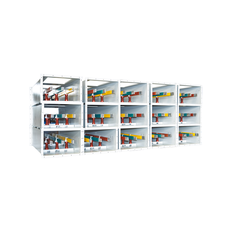
Jiangsu Wopeng Power Technology Co., Ltd. develops and manufactures a broad range of high- and low-voltage busbar systems, including copper and aluminum tubular busbars, epoxy resin vacuum-cast tube busbars, wind power tubular busbars, compact busbar systems, and sliding contact line systems. With modern vacuum casting, CNC machining, automated assembly, and standardized inspection capabilities, the company provides engineered busbar solutions for substations, power plants, renewable energy projects, industrial facilities, rail transit, and other demanding applications.
This article explains the construction, technical advantages, manufacturing processes, application value, and selection considerations of ultra-high voltage magnesium-aluminum alloy tubular bus bars. It also compares the product with copper and ordinary aluminum busbars and summarizes the principal capabilities that a qualified manufacturer should provide.
1. The Role of Tubular Bus Bars in Ultra-High Voltage Systems
A busbar is a low-impedance conductor used to collect, distribute, or transfer electrical power between major equipment units. In a high-voltage substation, busbars may connect transformers, circuit breakers, disconnectors, voltage transformers, reactors, generators, and outgoing transmission circuits. The conductor must carry normal operating current continuously while also surviving short-circuit forces, switching events, lightning impulses, thermal cycling, wind loading, vibration, and environmental exposure.
In ultra-high voltage systems, the busbar is not simply a metal connection. It is part of an integrated electrical and mechanical system. Its geometry influences electric-field distribution, corona behavior, electromagnetic forces, cooling, support spacing, insulation coordination, and the overall dimensions of the substation. A poorly selected conductor may increase energy losses, require more structural supports, create installation difficulties, or reduce operational reliability.
The tubular configuration provides several practical advantages over a solid conductor of equivalent electrical performance. A tube can offer a favorable ratio between cross-sectional area and structural stiffness. The outer surface supports heat dissipation and can be designed to provide more uniform electric-field behavior. The hollow profile also reduces unnecessary mass in applications where a very large solid cross-section would otherwise be required.
Magnesium-aluminum alloy further improves the balance between weight and strength. Aluminum provides good conductivity and low density, while magnesium contributes to specific strength and can help improve the structural performance of the alloy when properly controlled. Additional alloying strategies, including rare-earth and heat-resistant formulations, can be used to improve resistance to thermal degradation, vibration, and demanding outdoor conditions.
2. Product Composition and Alloy Options
The ultra-high voltage magnesium-aluminum alloy tubular bus bar product family includes several alloy options selected according to current capacity, mechanical requirements, temperature conditions, span, installation environment, and project specifications. Typical material categories include 6063G aluminum-magnesium alloy, LF21Y aluminum-manganese alloy, 6R05 rare-earth aluminum alloy, and 2A14 heat-resistant aluminum alloy.
Each alloy has a different balance of conductivity, strength, formability, heat resistance, corrosion behavior, and process compatibility. The final material selection should therefore be based on the complete operating condition rather than on a single performance value. For example, a long-span outdoor installation may emphasize tensile strength, bending resistance, and vibration performance, while a compact indoor substation may place greater emphasis on conductivity, thermal capacity, and insulation integration.
The alloy formulation is optimized to balance three basic requirements. First, the conductor must provide a sufficiently low electrical resistance for efficient transmission. Second, it must maintain structural stability under its own weight, support reactions, wind pressure, short-circuit forces, and thermal expansion. Third, it must retain its properties after long exposure to temperature variation, moisture, pollution, salt fog, ultraviolet radiation, and other environmental stresses.
Material quality begins before the tube is formed. The chemical composition, raw material cleanliness, melt treatment, casting conditions, and heat-treatment parameters influence the final electrical and mechanical properties. A professional manufacturer must control these variables through documented procedures and inspection records. Consistent material production is especially important for ultra-high voltage applications because local defects, inclusions, or nonuniform microstructures can reduce service reliability.
2.1 6063G Aluminum-Magnesium Alloy
6063G aluminum-magnesium alloy is suitable for applications requiring a practical combination of conductivity, corrosion resistance, surface quality, and structural performance. The alloy can support precision forming and surface treatment, making it useful for tubular conductors that must interface with insulation, fittings, supports, and connection hardware.
Its relatively good processability helps manufacturers produce tubes with controlled dimensions and smooth external surfaces. A consistent surface is important for electric-field management, coating or oxidation treatment, insulation bonding, and the reduction of localized stress concentration.
2.2 LF21Y Aluminum-Manganese Alloy
LF21Y aluminum-manganese alloy is commonly considered when corrosion resistance and stable forming behavior are important. It may be suitable for outdoor installations exposed to humidity, industrial pollution, coastal atmospheres, or temperature cycling. Its performance must be evaluated together with the selected surface treatment and connection system.
In a complete busbar assembly, the alloy is only one part of the corrosion-control strategy. End fittings, fasteners, support interfaces, protective coatings, drainage arrangements, and joint design also influence long-term durability.
2.3 6R05 Rare-Earth Aluminum Alloy
Rare-earth aluminum alloy formulations are used to refine the material structure and improve the balance of strength, conductivity, heat resistance, and corrosion performance. The addition of rare-earth elements must be accurately controlled. When processed correctly, the material can provide a stable microstructure suitable for high-performance tubular conductors.
This type of alloy may be valuable in projects where electrical loading, mechanical span, and elevated operating temperature occur simultaneously. The final performance depends on the complete production route, including casting, hot working, cold drawing, heat treatment, dimensional control, and testing.
2.4 2A14 Heat-Resistant Aluminum Alloy
2A14 heat-resistant aluminum alloy is intended for applications in which the busbar may experience high operating temperatures or considerable thermal cycling. The product information indicates operating temperatures reaching approximately 150°C to 200°C under applicable design conditions. Actual permissible temperature must always be confirmed through project calculations, applicable standards, joint design, insulation requirements, and manufacturer test data.
Heat-resistant materials are particularly relevant in high-current circuits, renewable energy collection systems, power plant connections, and locations where the conductor is exposed to frequent load changes. Maintaining mechanical and electrical stability at elevated temperature helps reduce the risk of performance deterioration during peak loading.
3. Structural Design of the Tubular Conductor
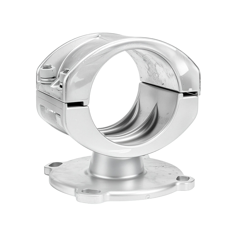
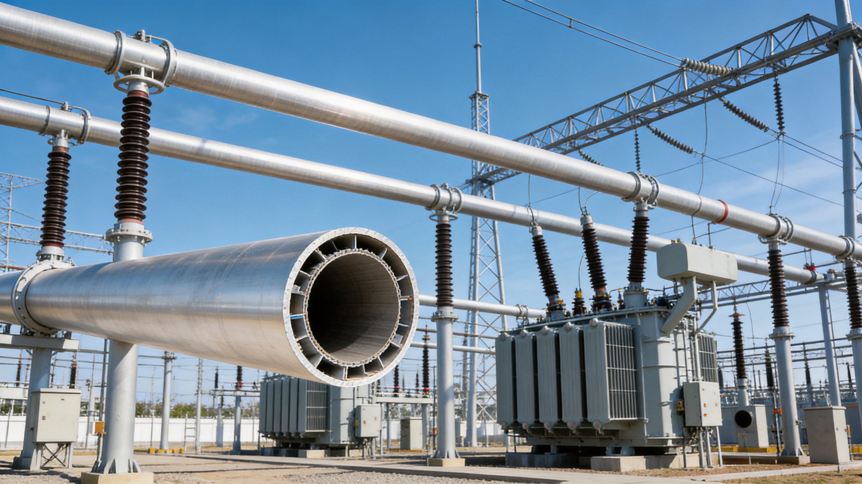
The tubular busbar consists of a hollow metallic conductor supported by an engineered arrangement of insulators, fittings, expansion elements, connection terminals, and, where required, external insulation or protective treatments. The tube diameter, wall thickness, length, alloy condition, support spacing, and joint configuration are selected according to the system voltage, rated current, short-circuit level, environmental loading, and installation layout.
The tubular shape helps distribute mechanical stress around the circumference. Compared with a flat conductor, a tube can provide better resistance to bending and torsion while maintaining a relatively efficient material distribution. This characteristic is useful for long-span applications, elevated structures, outdoor substations, wind power facilities, and installations where the number of supports must be limited.
The design also considers thermal expansion. Aluminum alloys expand when heated, and a long busbar run may experience measurable dimensional movement during load changes. Expansion joints, flexible connectors, sliding supports, or other movement-management devices may be incorporated into the system. Proper coordination between the tube, support structure, and connected equipment prevents excessive mechanical stress.
For ultra-high voltage applications, electric-field control is a central design objective. The conductor surface should be smooth and uniform, and the support and connection components should be arranged to avoid sharp points or irregularities that could intensify the local electric field. A well-designed tubular conductor contributes to a more uniform field distribution and helps reduce corona-related problems.
The complete system may use shielding or field-control components to maintain the required insulation coordination. The design should account for conductor diameter, phase spacing, support geometry, atmospheric conditions, altitude, pollution level, switching impulses, lightning impulses, and operating voltage. These factors must be validated through engineering calculations and appropriate type or routine testing.
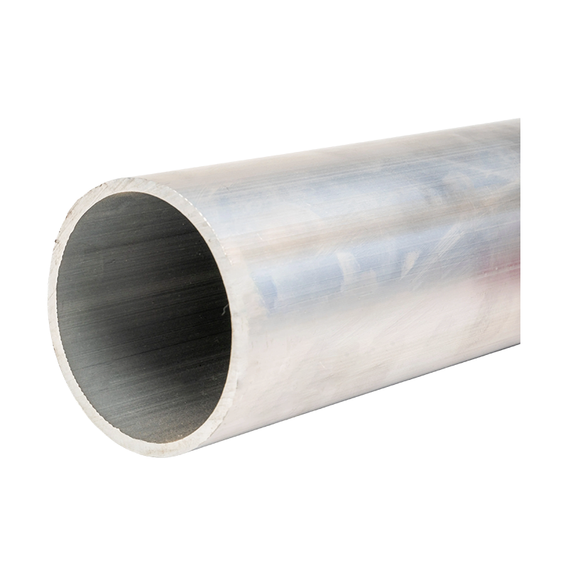
Ultra-high Voltage Magnesium-Aluminum Alloy Tubular Bus Bar
4. Main Technical Advantages
4.1 High Electrical Conductivity
Magnesium-aluminum alloy tubular busbars are designed to carry high current with controlled electrical losses. Aluminum-based conductors offer a lower density than copper while providing useful conductivity for large-scale transmission and distribution. The product information identifies electrical conductivity of at least 60% IACS for applicable product configurations, although the guaranteed value must be confirmed for the selected alloy, temper, dimensions, and manufacturing condition.
High conductivity reduces resistive losses and limits temperature rise during normal operation. Lower losses can improve the energy efficiency of a power transmission system and reduce the thermal burden on surrounding insulation, supports, joints, and equipment. In a large substation or power plant, even a modest reduction in conductor loss can produce meaningful operational benefits over the service life of the installation.
4.2 High Current-Carrying Capacity
The tubular busbar is designed for large-current applications and can be configured for rated currents that may reach approximately 12,000 A in suitable designs. Current capacity depends on alloy conductivity, tube dimensions, allowable temperature rise, ambient temperature, wind speed, solar radiation, installation orientation, surface condition, joint resistance, and applicable electrical standards.
The external tubular surface supports heat transfer to the surrounding air. A suitable surface finish and a carefully engineered support arrangement can improve convective cooling. Maintaining a controlled conductor temperature helps preserve mechanical properties and reduces the risk of accelerated aging in adjacent insulation and connection components.
4.3 Low Weight and Reduced Structural Loading
One of the most important advantages of an aluminum-based tubular busbar is its lower density compared with copper. A lighter conductor can reduce the load on support insulators, steel structures, foundations, lifting equipment, and transportation systems. It may also permit longer support spans or simplify the handling of large components during installation.
The product information indicates a typical weight range of approximately 8 to 12 kg per meter for a representative ultra-high voltage magnesium-aluminum alloy tubular busbar configuration. The actual weight varies with outer diameter, wall thickness, alloy, length, fittings, and design current. It should not be treated as a universal value for every project.
Reduced weight is particularly valuable in difficult construction environments. Mountainous substations, offshore wind projects, high-altitude power stations, and rail transportation facilities may impose strict limits on transport routes, lifting capacity, foundation size, or installation access. A lighter busbar can lower logistical complexity without sacrificing the required structural performance.
4.4 Mechanical Strength and Long-Span Capability
The alloy and tubular geometry provide a combination of tensile strength, bending resistance, vibration resistance, and torsional stability. The product information identifies tensile strength in the approximate range of 180 to 250 MPa for applicable configurations. The final value depends on alloy grade, temper, heat treatment, wall thickness, and testing conditions.
A strong tubular conductor can support wider installation spans than a conventional design when the complete system has been engineered accordingly. The stated maximum support span may reach approximately 8 meters in suitable applications. Span capability must be verified through calculations for sag, deflection, wind pressure, ice loading, short-circuit forces, thermal movement, and support strength.
Longer spans can reduce the number of insulators, brackets, steel structures, and connection points. This may simplify installation and maintenance while improving the visual and spatial organization of a substation. However, a longer span also increases the importance of accurate mechanical analysis and careful alignment during assembly.
4.5 High-Temperature Performance
In high-current systems, the conductor may experience substantial heating. Heat-resistant aluminum alloy options are developed to maintain stable electrical and mechanical behavior at elevated operating temperatures. The product range is designed for operating conditions that may reach approximately 150°C to 200°C, subject to the selected design and applicable technical requirements.
High-temperature capability provides additional operating flexibility during peak demand, emergency loading, renewable energy fluctuations, or temporary system reconfiguration. It also helps the conductor withstand repeated thermal cycles. Nevertheless, the temperature limit of the complete assembly is determined not only by the conductor but also by joints, insulation, supports, fittings, and nearby equipment.
4.6 Corona and Electric-Field Control
Corona discharge can produce audible noise, radio interference, ozone, energy loss, and long-term deterioration of nearby insulation. The risk increases with voltage, conductor surface irregularity, sharp edges, contamination, and unsuitable component geometry.
The tubular conductor design supports a relatively uniform external electric field when the surface, fittings, and support arrangement are properly engineered. Full shielding and field-control measures can further reduce local field concentration. Smooth tube production, controlled end finishing, rounded connection components, and correct installation alignment are all important to corona performance.
Corona-free or low-corona operation cannot be guaranteed by the conductor material alone. It requires system-level design validation, including appropriate testing under the specified voltage, altitude, humidity, pollution, and configuration conditions.
4.7 Corrosion and Weather Resistance
Outdoor substations and renewable energy facilities are exposed to moisture, temperature variation, industrial contaminants, salt fog, ultraviolet radiation, dust, and windborne particles. Magnesium-aluminum alloy tubular busbars can be combined with advanced surface oxidation or other protective treatments to improve corrosion resistance and maintain a stable interface with insulation and fittings.
Special surface treatment can also improve adhesion between the conductor and insulation systems such as epoxy vacuum casting or PTFE wrapping. A controlled surface condition helps prevent weak bonding, delamination, moisture ingress, and localized electrical defects.
For coastal or offshore applications, corrosion protection must be designed for the entire assembly. Dissimilar-metal contact, drainage, fastener selection, joint sealing, surface damage during installation, and maintenance access should all be reviewed. A material with good intrinsic corrosion resistance still requires correct system design.
4.8 Ice, Wind, and Seismic Resistance
Outdoor conductors may accumulate ice or experience significant wind pressure. Ice increases the effective diameter and weight of the conductor, while wind creates additional transverse loading and vibration. Special surface treatment and suitable geometry can help reduce ice adhesion, although the actual performance depends on local climate and design conditions.
The tubular structure also provides useful resistance to vibration and mechanical disturbance. In regions affected by earthquakes, the busbar system must be coordinated with flexible connections, support insulators, structural frames, and equipment terminals. Seismic performance should be verified through calculations and, when required, qualification testing.
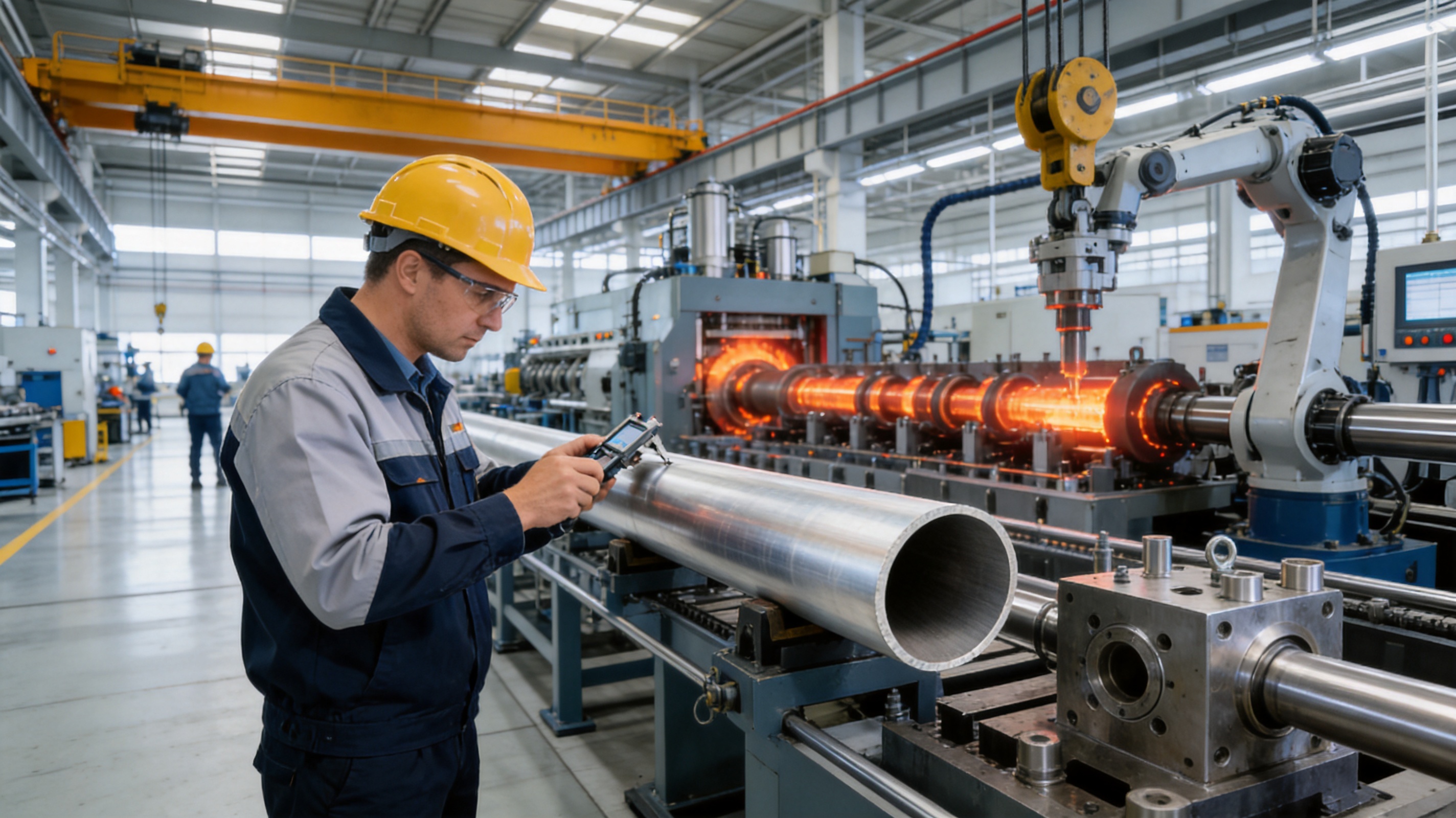
5. Advanced Manufacturing Processes
The performance of an ultra-high voltage tubular busbar depends heavily on its manufacturing route. High conductivity, dimensional accuracy, smoothness, mechanical strength, and insulation compatibility cannot be achieved consistently through basic tube forming alone. The production process must control metallurgy, thermal history, geometry, surface condition, and final assembly.
5.1 Horizontal Hot-Top Casting
Horizontal hot-top casting is used to produce a controlled starting billet with improved material purity and microstructural uniformity. The process manages the flow and solidification of molten alloy so that the cast material has fewer undesirable variations along its length and cross-section.
Material cleanliness is important for electrical and mechanical reliability. Inclusions, gas porosity, segregation, and coarse structural defects may reduce conductivity or become initiation points for cracking. Casting parameters, melt treatment, temperature control, cooling conditions, and billet inspection must therefore be managed through standardized procedures.
A uniform billet provides a more reliable foundation for subsequent hot working and tube production. It helps reduce property variation between different sections of the same conductor and supports more predictable results during heat treatment and cold drawing.
5.2 Transverse Piercing and Hot Rolling
Transverse piercing and hot rolling are used to form seamless tubes. Unlike welded tube production, the seamless route avoids a longitudinal weld seam that could become a localized weakness or require additional inspection and treatment.
During piercing, the billet is transformed into a hollow form. Subsequent hot rolling controls the outer diameter, wall thickness, and material structure. The process must be accurately synchronized with alloy temperature and deformation requirements. Excessive or insufficient deformation can affect grain structure, surface quality, dimensional stability, and mechanical properties.
Seamless manufacturing is particularly useful for high-voltage tubular conductors because it provides a continuous metallic path around the circumference. It can improve mechanical uniformity and reduce concerns associated with weld quality, heat-affected zones, or seam-related field irregularities.
5.3 Thermomechanical Treatment
Thermomechanical treatment combines controlled heating, deformation, cooling, and, where applicable, aging or heat treatment to obtain the desired balance of strength and conductivity. The treatment modifies the microstructure and helps stabilize the material for service.
For heat-resistant or rare-earth alloy products, thermomechanical control is especially important. The manufacturer must maintain accurate temperature ranges, deformation schedules, holding times, and cooling rates. Inconsistent treatment may produce differences in hardness, tensile strength, elongation, conductivity, or residual stress.
Documented process parameters allow the manufacturer to reproduce performance from one production batch to another. They also support traceability when customers require material certificates, inspection reports, or project-specific quality documentation.
5.4 Multipass Cold Drawing
Multipass cold drawing is used to refine the tube dimensions and improve dimensional accuracy. Rather than relying on a single large reduction, multiple controlled passes gradually reduce the diameter or wall thickness while improving surface quality and geometric consistency.
Cold drawing can help control straightness, concentricity, outer diameter, inner diameter, and wall-thickness variation. These characteristics are important when the tube must fit accurately with connection fittings, insulation components, supports, and expansion elements.
The process also influences work hardening and residual stress. Appropriate intermediate treatment and final conditioning may be necessary to obtain the required mechanical properties without creating excessive stress or dimensional instability.
5.5 Surface Oxidation and Protective Treatment
Surface treatment is used to improve corrosion resistance, control surface behavior, and support insulation adhesion. The treatment must be uniform and compatible with the selected insulation system. Common project requirements may involve epoxy vacuum casting, PTFE wrapping, or other customized insulation processes.
Before treatment, the tube surface should be cleaned and prepared to remove contaminants, oxides, oil, and loose particles. After treatment, the manufacturer should verify surface coverage, adhesion, visual quality, and compatibility with subsequent assembly processes.
5.6 CNC Machining and Precision Assembly
End preparation, drilling, slotting, fitting interfaces, and connection components must be manufactured with accurate dimensions. CNC machining supports repeatability and helps maintain alignment across long conductor sections. Precision is particularly important where the busbar connects to transformers, circuit breakers, generator terminals, or other equipment with limited tolerance for misalignment.
Automated or semi-automated assembly technologies can improve consistency in fastening, insulation installation, component positioning, and final inspection. Skilled production personnel remain essential for process verification, adjustment, and the handling of project-specific configurations.
6. Quality Control and Testing
A reliable ultra-high voltage tubular busbar manufacturer should apply quality control from incoming raw materials through final shipment. Quality assurance is not limited to a final visual inspection. It includes chemical composition checks, dimensional inspection, mechanical testing, electrical testing, surface examination, insulation verification, assembly control, and documentation.
6.1 Raw Material and Metallurgical Control
Raw materials should be inspected against the approved alloy specification. Chemical composition, billet condition, surface quality, and traceability are basic requirements. Where applicable, the manufacturer should retain records linking each finished tube to its billet, production batch, heat-treatment condition, and inspection results.
6.2 Dimensional Inspection
Important dimensional parameters include outer diameter, inner diameter, wall thickness, straightness, roundness, length, end geometry, hole position, and connection-interface accuracy. Dimensional consistency influences current distribution, mechanical fit, electric-field uniformity, and installation efficiency.
Inspection tools may include calibrated gauges, coordinate measuring equipment, laser measurement systems, ultrasonic thickness instruments, and other suitable devices. Measurement procedures should define reference points, tolerances, environmental conditions, and acceptance criteria.
6.3 Electrical and Insulation Tests
Electrical tests may include resistance measurement, conductivity verification, dielectric tests, insulation resistance tests, partial discharge evaluation, and high-voltage withstand tests, depending on the product configuration and project requirements. The exact test program should follow the applicable standards and approved technical specification.
For insulated or cast systems, insulation thickness, curing quality, void control, adhesion, and surface integrity are critical. Vacuum casting is often used to reduce air entrapment and improve insulation uniformity. The manufacturer should verify that the insulation system remains compatible with the conductor surface treatment and operating temperature.
6.4 Mechanical Verification
Mechanical verification may include tensile testing, bending tests, vibration assessment, connection strength testing, support-load evaluation, and dimensional stability checks. For long-span installations, calculations and tests should address sag, wind, ice, thermal expansion, seismic movement, and short-circuit forces.
6.5 Routine and Third-Party Testing
Routine factory tests help identify production deviations before shipment. Type tests or design verification tests demonstrate that a product configuration can meet specified electrical, thermal, mechanical, and environmental requirements. Cooperation with qualified third-party testing institutions can provide independent validation for customers, engineering contractors, utilities, and infrastructure owners.
When evaluating a supplier, customers should request relevant type-test reports, material certificates, inspection records, quality-management documentation, and project references. The reports should correspond to the actual product family, voltage class, conductor dimensions, insulation system, and connection design being proposed.
7. Comparison with Conventional Busbar Materials
Traditional copper busbars remain important in many electrical systems because of their high conductivity, established manufacturing base, and broad availability. However, copper has a high density, which increases the weight of large conductors and can raise the load on supports and foundations. Transportation and installation may also become more difficult as conductor dimensions increase.
Ordinary aluminum busbars offer lower weight and lower material density than copper, but their performance may be limited by the selected alloy, geometry, surface condition, and mechanical requirements. A carefully engineered magnesium-aluminum alloy tubular busbar is intended to improve the balance among conductivity, strength, thermal capability, and environmental durability.
| Characteristic | Magnesium-Aluminum Alloy Tubular Busbar | Traditional Copper Busbar | Ordinary Aluminum Busbar |
|---|---|---|---|
| Typical material density | Low | High | Low |
| Large-current suitability | High when correctly sized and cooled | High | Dependent on alloy and section design |
| Mechanical strength-to-weight ratio | High for optimized alloy and tube geometry | High strength but greater mass | Moderate to high depending on alloy |
| Heat-resistant options | Available through selected alloy grades | Generally stable but heavy | Available, but specification dependent |
| Structural span potential | High when supported by engineering calculations | High, but with increased support loading | Dependent on section stiffness and alloy |
| Corrosion strategy | Alloy selection plus surface treatment | Material selection plus joint and surface protection | Alloy selection plus surface treatment |
| Installation handling | Relatively easy because of lower weight | More demanding for large sections | Relatively easy |
| UHV application potential | Suitable when validated for the specified system | Suitable when designed for the specified system | Dependent on electrical, mechanical, and corona requirements |
The figures and comparisons used for product selection should be treated as indicative rather than universal. Actual performance depends on conductor diameter, wall thickness, alloy condition, rated current, ambient conditions, support spacing, connection design, and applicable standards. The most meaningful comparison is therefore based on the complete installed system, including supports, insulation, fittings, foundations, transportation, maintenance, and lifetime operating losses.
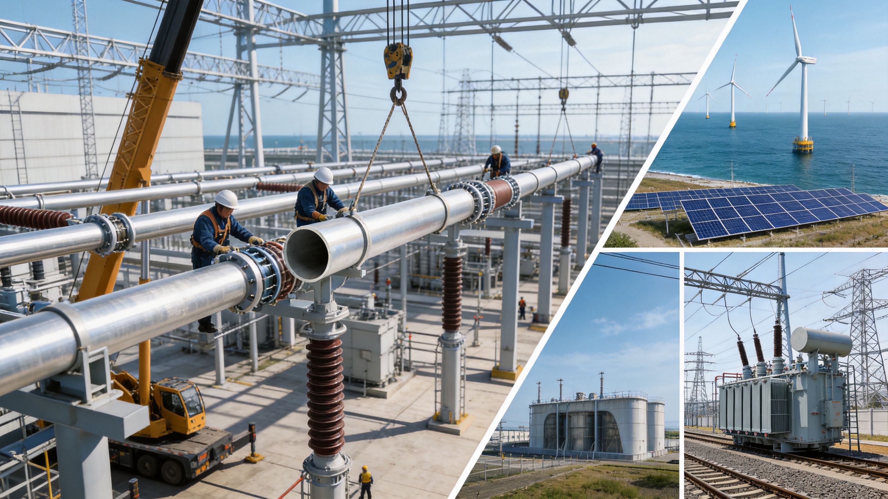
8. Application Areas
8.1 Ultra-High Voltage Substations
Substations rated at 500 kV and above require busbars that can connect major equipment with high electrical reliability and controlled electric-field performance. Tubular busbars may be used for main bus sections, equipment connections, transformer-side connections, and other high-current paths.
The lightweight construction can reduce support loads and simplify the arrangement of steel structures. The smooth tubular surface and field-control design can assist with corona management. Outdoor corrosion protection and weather resistance are also valuable for substations exposed to changing climate conditions.
8.2 Power Generation Plants
Hydropower, thermal power, nuclear-related auxiliary systems, and renewable energy plants all require reliable high-current connections. A tubular busbar can connect generators, step-up transformers, switchgear, and grid interface equipment.
Power plants often experience load changes, maintenance switching, vibration, and thermal cycling. The mechanical and heat-resistant properties of the selected alloy can support stable operation under these conditions. Project-specific design must consider generator terminal forces, short-circuit current, enclosure or outdoor exposure, and connection flexibility.
8.3 Wind Power and Photovoltaic Facilities
Renewable energy facilities frequently use long electrical routes and may be located in remote or environmentally exposed areas. Wind farms experience vibration and dynamic loading, while photovoltaic facilities may be exposed to high solar radiation, dust, humidity, and large daily temperature changes.
Magnesium-aluminum alloy tubular busbars can support lightweight system design and provide corrosion resistance when correctly treated. Offshore wind projects and coastal renewable energy facilities may particularly benefit from a carefully engineered corrosion-control system, including compatible fasteners, sealing, drainage, and inspection access.
8.4 Rail Transportation
Rail transit systems require reliable power distribution with strict requirements for vibration, space utilization, maintenance access, and operational continuity. Tubular busbars may be used in substations, traction power facilities, and high-current distribution equipment.
The high strength-to-weight ratio can reduce structural loading, while the tubular configuration can be adapted to compact layouts. Vibration resistance and connection durability are important because repeated mechanical excitation may occur throughout the service life.
8.5 Industrial Power Distribution
Metallurgical plants, chemical facilities, manufacturing sites, and other heavy industries often operate large electrical loads under demanding environmental conditions. Their distribution systems may need to withstand heat, dust, corrosive gases, vibration, and frequent load changes.
The busbar can be configured to support high current and elevated temperature requirements. The final design should include appropriate enclosure, ventilation, insulation, surface protection, and maintenance provisions based on the industrial atmosphere.
8.6 High-Altitude and Coastal Installations
High-altitude substations may experience reduced air density, lower natural cooling capacity, stronger ultraviolet exposure, and more demanding insulation coordination. Coastal and offshore systems face salt fog, high humidity, and accelerated corrosion risks.
For both environments, conductor design must be coordinated with insulation distance, corona control, thermal calculations, surface treatment, and environmental testing. The product’s alloy and tubular construction provide a foundation for these applications, but project-specific qualification remains essential.
9. Insulation and System Integration
The conductor must be integrated with an insulation system that remains reliable at the specified voltage, temperature, humidity, and mechanical loading. Epoxy resin vacuum casting and PTFE wrapping are examples of insulation processes that may be compatible with magnesium-aluminum alloy tubular busbars when the conductor surface is properly prepared.
Insulation adhesion is influenced by surface roughness, cleanliness, oxide condition, treatment chemistry, curing temperature, resin formulation, and mechanical movement. If the interface is poorly controlled, thermal cycling may cause cracking, delamination, or moisture penetration. Special oxidation treatment can improve bonding and create a more stable interface between the metallic tube and the insulation layer.
Vacuum casting is useful for reducing internal voids in resin insulation. Voids and contamination can create local electric-field enhancement and partial discharge. The casting process should therefore control resin mixing, degassing, mold preparation, filling speed, curing temperature, and post-curing conditions.
PTFE wrapping may be selected for applications requiring flexibility, chemical resistance, or a specific insulation structure. The wrapping tension, overlap, termination, and protection against moisture ingress must be carefully controlled. The insulation design should also accommodate conductor expansion and mechanical movement without creating excessive stress.
System integration includes more than the conductor and insulation. The design must coordinate clamps, supports, expansion joints, flexible connectors, grounding arrangements, enclosure interfaces, and equipment terminals. Every connection should maintain low contact resistance and sufficient mechanical strength throughout the expected service life.
10. Engineering and Installation Considerations
Before production begins, the manufacturer and project engineering team should confirm the system voltage, rated current, short-circuit level, frequency, installation altitude, pollution category, ambient temperature, wind speed, ice loading, seismic requirements, support span, conductor orientation, and connection arrangement.
Electrical calculations should determine current capacity, voltage drop, losses, temperature rise, electric-field distribution, corona performance, insulation coordination, and short-circuit forces. Mechanical calculations should determine sag, deflection, support reactions, thermal expansion, vibration, wind loading, ice loading, and seismic movement.
Transport and handling plans should be prepared for long tubular sections. The tubes should be supported at sufficient points during lifting and transportation to prevent bending or local deformation. Protective packaging should prevent impact damage, contamination, and moisture accumulation. Machined ends and treated surfaces require particular protection.
During installation, alignment should be verified before final tightening of supports and connection hardware. Excessive force must not be used to bring misaligned equipment terminals into position. Expansion joints and flexible connectors should be installed according to the specified movement direction and adjustment range.
Connection surfaces should be clean and free from damage. Contact pressure, fastener torque, joint compound, bimetallic interfaces, and sealing arrangements should follow the approved installation procedure. Incorrect joint preparation can increase contact resistance, create local heating, and reduce the effective current capacity of the system.
After installation, the system should undergo visual inspection, dimensional verification, insulation testing, resistance measurement, high-voltage testing, partial discharge assessment where applicable, and functional checks of connected equipment. Test records should be retained as part of the project quality file.
11. Why Manufacturer Capability Matters
A high-voltage busbar is a customized engineered product rather than a generic length of metal tube. Its performance depends on material selection, manufacturing precision, insulation integration, connection design, testing, and field installation. Choosing a manufacturer with capabilities across these areas reduces technical and coordination risks.
Jiangsu Wopeng Power Technology Co., Ltd. was founded in 2018 as a specialized high- and low-voltage busbar system enterprise. Its product portfolio covers systems from low voltage to 35 kV, together with copper and aluminum tubular busbars, wind power tube busbars, compact busbar systems, epoxy resin vacuum-cast products, and sliding contact line systems.
The company’s engineering team includes engineers, technical specialists, and production professionals experienced in power equipment technology. This combination supports the development of customized solutions for power generation, substations, wind energy, industrial manufacturing, rail transit, and large commercial facilities.
Modern production lines include vacuum casting systems, CNC machining equipment, and automated assembly technologies. These facilities support repeatable production, accurate component preparation, consistent insulation processing, and efficient assembly. Standardized inspection includes high-voltage tests, insulation tests, mechanical verification, and routine quality checks.
Cooperation with third-party testing institutions provides independent validation of safety and performance where required. Such cooperation is valuable for projects involving utilities, engineering contractors, international customers, or critical infrastructure owners that require formal evidence of product conformity.
The company reports that its products operate across more than 17 provinces and key industrial sectors. This project experience can help inform practical decisions concerning layout, installation, environmental adaptation, maintenance, and integration with existing power equipment.
12. Customization and OEM Support
Ultra-high voltage projects rarely use identical conductor dimensions or identical installation arrangements. Customers may require specific alloy grades, tube diameters, wall thicknesses, lengths, connection fittings, insulation systems, support spacing, surface treatments, or packaging configurations.
A capable OEM manufacturer should review the customer’s technical drawings, electrical parameters, mechanical calculations, applicable standards, and installation conditions before issuing a final proposal. Engineering support may include conductor selection, thermal analysis, support arrangement, expansion-joint design, insulation coordination, connection interface review, and test-plan preparation.
Customization should be controlled through approved drawings and documented change procedures. Changes to alloy, wall thickness, surface treatment, joint design, or insulation process can affect multiple performance characteristics. A professional supplier should identify these interactions before production rather than treating each change as an isolated adjustment.
OEM support also includes packaging, labeling, documentation, spare parts, installation guidance, inspection records, and after-sales communication. Clear documentation helps contractors install the product correctly and allows owners to maintain a complete technical record for future operation and expansion.
13. Lifecycle and Economic Value
The purchase price of a busbar is only one part of its total cost. A complete economic evaluation should include transportation, lifting, supports, foundations, installation labor, electrical losses, maintenance, replacement risk, and service life.
The lower mass of a magnesium-aluminum alloy tubular busbar may reduce transportation and lifting requirements. Reduced support loading can influence the cost of steelwork, insulators, and foundations. A long-span configuration may reduce the quantity of support structures and simplify the layout.
Low electrical losses can provide continuing operating savings. The financial value depends on current, operating hours, electricity cost, conductor length, ambient conditions, and system efficiency. Heat-resistant capability may also provide operational value by allowing the system to manage temporary high-load conditions without immediate replacement or major modification.
Long service life is another important factor. With appropriate anti-corrosion treatment and normal operating conditions, the product information indicates a potential service life of approximately 30 to 40 years in ultra-high voltage power systems. Actual life depends on environmental exposure, electrical loading, maintenance, joint condition, insulation aging, and compliance with operating limits.
14. Recommended Selection Checklist
When selecting an ultra-high voltage magnesium-aluminum alloy tubular busbar, the buyer should begin by confirming the voltage class and rated current. The design should identify whether the application is 220 kV, 500 kV, 750 kV, ±800 kV, 1000 kV, or another voltage level. The selected product must be validated for the actual system configuration rather than selected solely from a general catalog description.
The alloy and temper should be reviewed against conductivity, tensile strength, heat resistance, corrosion conditions, forming requirements, and connection compatibility. Material certificates and relevant test data should be available for the proposed batch or product configuration.
The mechanical design should address support span, sag, wind, ice, vibration, seismic forces, short-circuit forces, thermal expansion, lifting, and transportation. If the application requires a span of up to approximately 8 meters, the complete arrangement should be checked by calculation and, where required, qualification testing.
The electrical design should address current capacity, temperature rise, power loss, corona, radio interference, insulation level, lightning impulse, switching impulse, and partial discharge. Surface finish, conductor diameter, shielding, support geometry, and connection components should be evaluated together.
The environmental design should consider salt fog, industrial pollution, humidity, ultraviolet exposure, high altitude, low temperature, high temperature, wind, ice, and seismic conditions. Surface treatment and joint protection should be selected accordingly.
Finally, the customer should review manufacturer capabilities, production equipment, quality systems, test resources, engineering support, project experience, delivery schedule, packaging, installation guidance, warranty, and after-sales service.
15. Frequently Asked Questions
Q1: What is an ultra-high voltage magnesium-aluminum alloy tubular busbar?
An ultra-high voltage magnesium-aluminum alloy tubular busbar is a hollow metallic conductor designed for high-current transmission and distribution in high- and ultra-high voltage power systems. It uses an aluminum-based alloy containing magnesium or other controlled alloying elements and is manufactured as a seamless or precision-formed tube. The product is integrated with supports, fittings, insulation, and field-control components to create a complete busbar system.
Q2: Which voltage levels can this product serve?
The product family is intended for applications including 220 kV, 500 kV, 750 kV, ±800 kV, and 1000 kV scenarios, subject to the selected design and qualification requirements. The applicable voltage level must be confirmed through system calculations, insulation coordination, type testing, and project specifications.
Q3: Is it lighter than a copper busbar?
Yes. Aluminum-based alloys have a substantially lower density than copper. The tubular structure also avoids unnecessary material in the center of a large conductor. The resulting reduction in weight can lower support loading and simplify transportation and installation. Actual weight depends on tube dimensions, alloy, fittings, insulation, and project design.
Q4: What current can the tubular busbar carry?
Suitable configurations may support rated currents up to approximately 12,000 A. Current capacity depends on conductor dimensions, alloy conductivity, allowable temperature rise, ambient conditions, wind, solar radiation, joint resistance, and installation arrangement. A project-specific thermal calculation is required before final selection.
Q5: Can the busbar operate at high temperatures?
Selected heat-resistant alloy configurations are designed for elevated operating temperatures that may reach approximately 150°C to 200°C under specified conditions. The actual allowable temperature is governed by the conductor, joints, insulation, supports, fittings, connected equipment, and applicable standards.
Q6: Is the product suitable for outdoor use?
Yes. The product can be designed for outdoor substations, wind power projects, photovoltaic facilities, coastal installations, and other exposed environments. Corrosion protection, surface treatment, sealing, drainage, fastener selection, and environmental qualification should be specified according to the site conditions.
Q7: Can it be used in offshore wind power projects?
It can be considered for offshore and coastal wind power systems where lightweight construction, corrosion resistance, and reliable high-current transmission are important. Salt fog, humidity, vibration, wind loading, connection protection, and maintenance access require special attention during engineering and qualification.
Q8: What insulation processes are compatible with the alloy tubular busbar?
The conductor can be compatible with insulation processes such as epoxy resin vacuum casting and PTFE wrapping when the surface is properly prepared and treated. The insulation system must be validated for adhesion, temperature, dielectric performance, mechanical movement, and environmental exposure.
Q9: Does a seamless tube improve reliability?
A seamless tube eliminates the longitudinal weld seam and its associated heat-affected zone. This can improve circumferential mechanical uniformity and reduce seam-related concerns. Reliability still depends on casting quality, hot rolling, cold drawing, heat treatment, surface condition, dimensional control, and final inspection.
Q10: What support span can the busbar achieve?
The product information indicates that a maximum support span may reach approximately 8 meters in suitable designs. The actual span depends on tube stiffness, weight, wind, ice, seismic conditions, short-circuit forces, allowable deflection, and support configuration. It must be confirmed through project-specific mechanical calculations.
Q11: How long can the product serve?
With appropriate anti-corrosion treatment and normal operating conditions, the expected service life may be approximately 30 to 40 years. Actual service life depends on loading, temperature, environment, joint maintenance, insulation condition, surface protection, and adherence to operating limits.
Q12: What documents should a customer request from the manufacturer?
Customers should request technical drawings, alloy and material certificates, dimensional inspection records, electrical and mechanical test reports, insulation test results, type-test or design-verification documents where applicable, installation instructions, maintenance recommendations, and quality-management documentation. The documents should correspond to the actual product configuration being supplied.
Q13: Can the product be customized?
Yes. Customization may include alloy grade, tube diameter, wall thickness, length, connection fittings, insulation method, surface treatment, support arrangement, expansion components, packaging, and labeling. All changes should be reviewed and approved through controlled technical documentation.
Q14: Why should the complete busbar system be evaluated rather than only the conductor?
Electrical, thermal, mechanical, and environmental performance depends on the interaction among the tube, supports, insulation, joints, fittings, equipment terminals, and surrounding structures. A high-quality conductor can still perform poorly if the connection resistance, support alignment, insulation interface, or expansion arrangement is unsuitable. System-level evaluation provides a more accurate basis for selection.
16. Conclusion
The ultra-high voltage magnesium-aluminum alloy tubular busbar is a specialized solution for power systems that demand high current capacity, controlled electrical loss, low structural weight, strong mechanical performance, heat resistance, and environmental durability. Its value comes from the combination of optimized alloy composition, tubular geometry, seamless tube production, thermomechanical treatment, multipass cold drawing, surface treatment, precision machining, and comprehensive testing.
Compared with heavy copper conductors, the product can reduce weight, support loading, transportation demands, and installation difficulty. Compared with ordinary aluminum busbars, optimized magnesium-aluminum, rare-earth, and heat-resistant alloy options can provide improved mechanical strength, temperature performance, corrosion resistance, and long-span potential when correctly specified.
The product is applicable to ultra-high voltage substations, power generation plants, renewable energy facilities, industrial power distribution systems, rail transit, coastal projects, offshore wind power, and high-altitude installations. Its performance must always be confirmed against the actual voltage, current, mechanical, insulation, environmental, and testing requirements of the project.
With experience in high- and low-voltage busbar systems, modern vacuum casting and machining equipment, automated assembly capabilities, standardized inspection procedures, and third-party testing cooperation, Jiangsu Wopeng Power Technology Co., Ltd. supports customers seeking customized tubular busbar solutions. Its engineering and manufacturing resources provide a practical foundation for developing safe, efficient, and reliable power transmission systems.
References
1. IEC 62271 Series, High-Voltage Switchgear and Controlgear.
2. IEC 60865 Series, Short-Circuit Currents: Calculation of Effects.
3. IEC 60071 Series, Insulation Coordination.
4. IEC 60137, Insulated Bushings for Alternating Voltages above 1,000 V.
5. ASTM B221, Standard Specification for Aluminum and Aluminum-Alloy Extruded Bars, Rods, Wire, Profiles, and Tubes.
6. ASTM B210, Standard Specification for Aluminum and Aluminum-Alloy Drawn Seamless Tubes.
7. Aluminum Association, Aluminum Standards and Data.
8. IEEE High-Voltage Engineering and Power Transmission Practice, technical guidance on insulation, corona, and electric-field control.
9. Manufacturer technical information for magnesium-aluminum alloy tubular busbar systems, alloy options, manufacturing processes, and application conditions.
10. Manufacturer quality and testing information for vacuum-cast insulation systems, CNC-machined components, automated assembly, and high-voltage busbar inspection.
Product: Ultra-high Voltage Magnesium-Aluminum Alloy Tubular Bus Bar



-
 +86-180 3625 3000
-
 admin@wpbusbar.com
-
 No. 8, Yanjin Road, Chengxi Industrial Park, Shanyang Town, Baoying County, Yangzhou City, Jiangsu Province, China
Copyright © Jiangsu Wopeng Power Technology Co., Ltd.
All Rights Reserved.
 Custom Insulated Bus Bar Manufacturer
Tubular Busbar System Factory
Custom Insulated Bus Bar Manufacturer
Tubular Busbar System Factory