

 EN

 English
 русский
 Français
 Español
 عربى
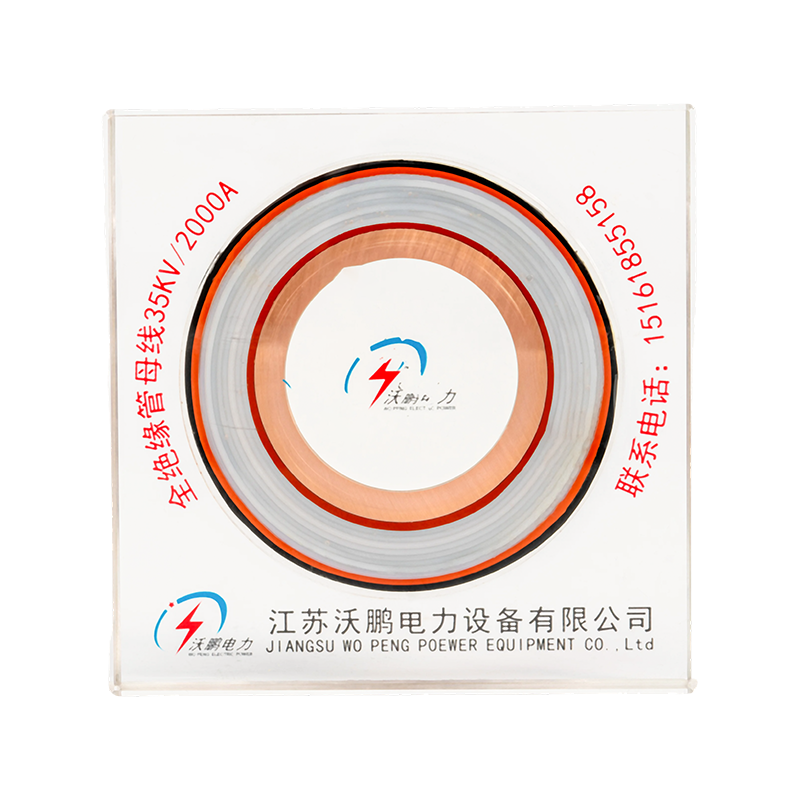
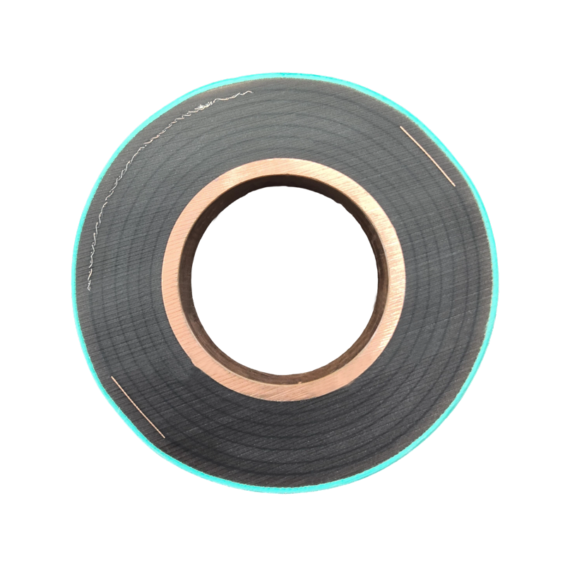
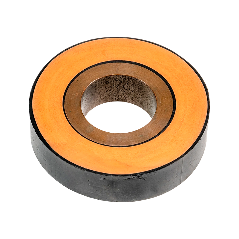
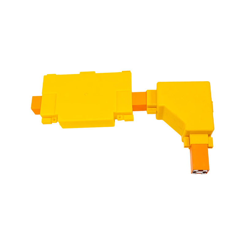

Ultra-High Voltage Magnesium-Aluminum Alloy Tubular Bus Bar: Materials, Performance, Manufacturing, and Applications
Content
- 1 1. The Role of Tubular Bus Bars in Ultra-High Voltage Systems
- 2 2. Material Engineering and Alloy Options
- 3 3. Technical Advantages of the Tubular Design
- 4 4. Manufacturing Process and Quality Control
- 5 5. Electrical, Thermal, and Mechanical Performance
- 6 6. Insulation Compatibility and Corona Control
- 7 7. Comparison with Conventional Busbar Solutions
- 8 8. Application Scenarios
- 9 9. Environmental Durability and Service Life
- 10 10. Engineering Selection Guide
- 11 11. Manufacturing and Engineering Strengths
- 12 12. Installation and Maintenance Considerations
- 13 13. Q&A: Ultra-High Voltage Magnesium-Aluminum Alloy Tubular Bus Bar
- 13.1 Q1: What is an ultra-high voltage magnesium-aluminum alloy tubular bus bar?
- 13.2 Q2: Which voltage levels can the product serve?
- 13.3 Q3: What alloys are available?
- 13.4 Q4: Why use a tubular conductor instead of a flat bus bar?
- 13.5 Q5: Is the product lighter than a copper bus bar?
- 13.6 Q6: What is the conductivity of the alloy tubular bus bar?
- 13.7 Q7: Can it operate at high temperatures?
- 13.8 Q8: Is the bus bar suitable for outdoor installations?
- 13.9 Q9: How is the seamless tube manufactured?
- 13.10 Q10: What insulation processes are compatible with the conductor?
- 13.11 Q11: What is the maximum support span?
- 13.12 Q12: What is the expected service life?
- 13.13 Q13: Can the product be customized?
- 13.14 Q14: What documentation should be requested before purchase?
- 14 14. Conclusion
- 15 References
- 16 Product: Ultra-high Voltage Magnesium-Aluminum Alloy Tubular Bus Bar
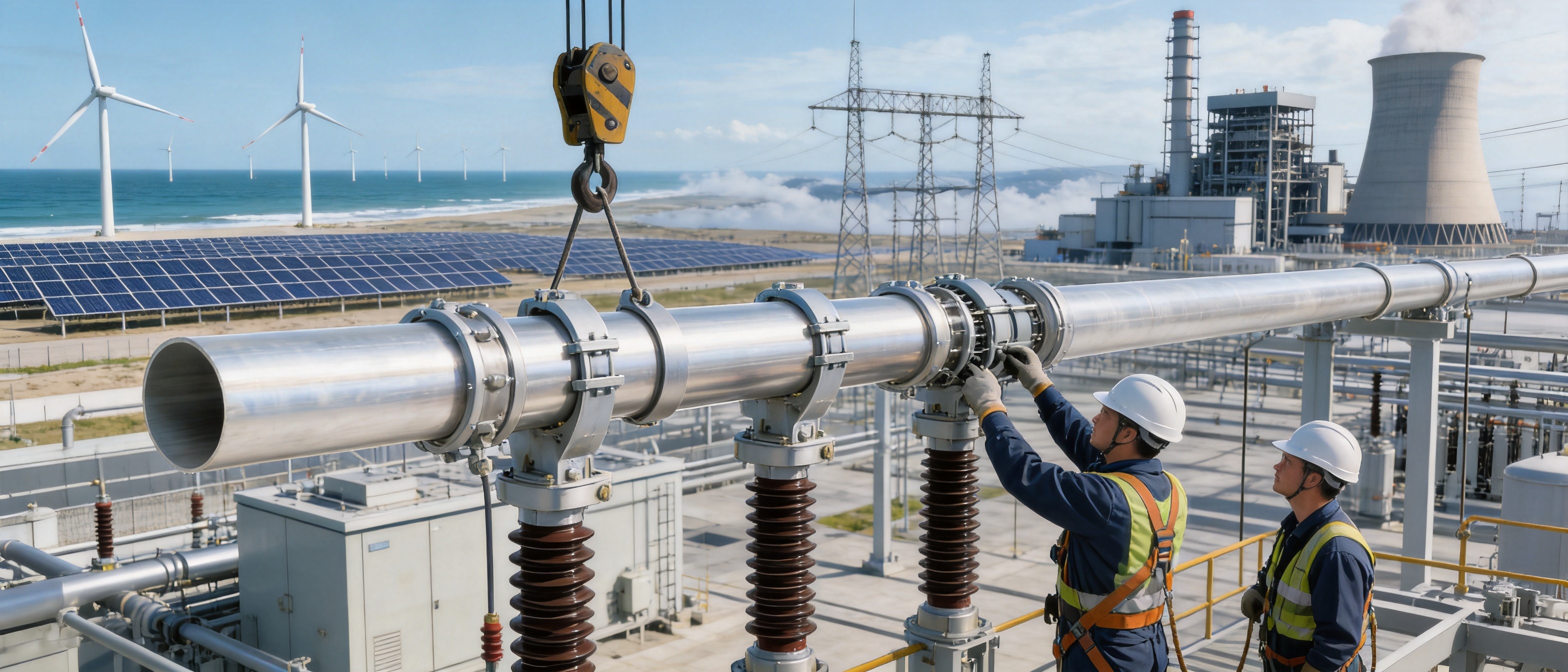
Ultra-high voltage power systems require conductive equipment that can carry large currents, withstand severe electrical and mechanical stresses, and operate reliably over many years. As transmission networks expand toward 500 kV, 750 kV, ±800 kV, and 1,000 kV applications, the design of busbar systems has become increasingly important. A tubular bus bar must provide high electrical conductivity while also maintaining mechanical stability, dimensional accuracy, insulation compatibility, weather resistance, and effective heat dissipation.
The ultra-high voltage magnesium-aluminum alloy tubular bus bar is developed to address these requirements. It combines the low density and conductivity of aluminum with the enhanced strength and functional benefits provided by carefully controlled alloying elements, including magnesium, manganese, and rare-earth additions. Its tubular geometry further improves rigidity, current distribution, surface electric-field control, and thermal performance compared with many conventional solid conductors.
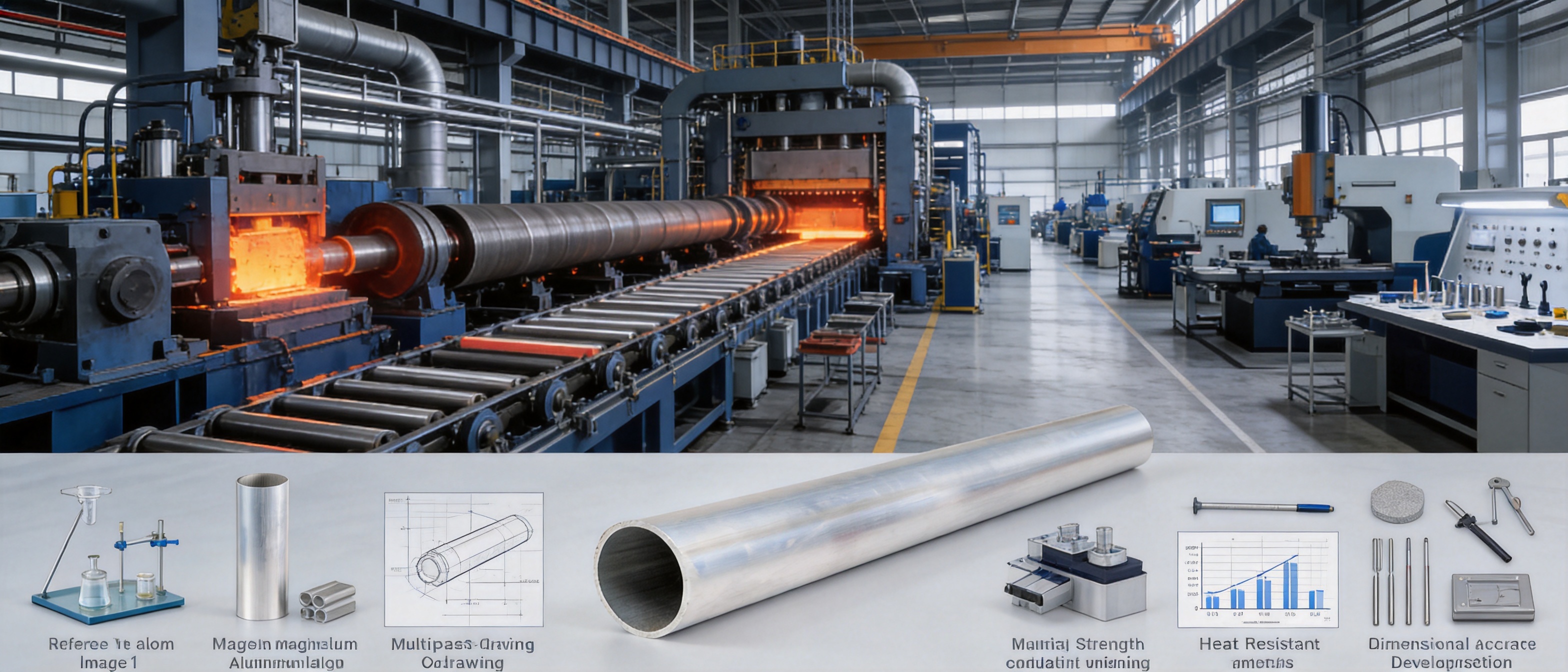
This product is intended for high-voltage and ultra-high voltage substations, power plants, renewable energy facilities, industrial distribution systems, transmission connection nodes, and other installations where high current capacity and dependable operation are essential. Through advanced alloy design, horizontal hot-top casting, transverse piercing hot rolling, thermomechanical treatment, cold drawing, and precision finishing, the conductor can be manufactured with stable dimensions and a consistent internal structure.
The product family includes 6063G aluminum-magnesium alloy, LF21Y aluminum-manganese alloy, 6R05 rare-earth aluminum alloy, and 2A14 heat-resistant aluminum alloy options. These materials allow the busbar system to be matched to different combinations of current, temperature, span, environmental exposure, mechanical load, and installation requirements.
1. The Role of Tubular Bus Bars in Ultra-High Voltage Systems
A bus bar is a central conductive path used to collect, distribute, or transfer electrical energy between major items of equipment. In a substation, bus bars may connect transformers, circuit breakers, disconnect switches, instrument transformers, reactors, and outgoing transmission circuits. In a power plant, they can carry generator output toward the grid. In renewable energy installations, they may connect collection systems, transformers, converters, and high-voltage switchgear.
At ultra-high voltage levels, the busbar is not simply a metal conductor. It is part of a coordinated electrical, mechanical, thermal, and insulation system. The conductor must control the electric field around its surface, limit corona activity, withstand short-circuit forces, accommodate thermal expansion, and preserve adequate clearances under wind, ice, vibration, and seismic loading.
Tubular construction provides several functional benefits. The circular cross-section offers high bending stiffness relative to material weight. It also presents a smooth outer surface that can help reduce local electric-field concentrations. The hollow section may provide an efficient relationship between mass, moment of inertia, and current-carrying capacity. Depending on the installation design, the tube can be supported across relatively long spans, reducing the quantity of support hardware and simplifying layout.
Ultra-high voltage systems also generate substantial electromagnetic and thermal stresses. During normal operation, the conductor must carry continuous current without excessive temperature rise. During faults, it may be exposed to very high short-circuit currents and strong electrodynamic forces. The combination of alloy properties and tubular geometry helps the bus bar maintain structural integrity during these demanding conditions.
1.1 Electrical Requirements
Electrical conductivity is one of the most important parameters in busbar selection. High conductivity reduces resistive losses and improves the efficiency of power transmission. It also helps control operating temperature because less heat is generated for a given current level.
For ultra-high voltage applications, conductivity must be evaluated together with surface condition, cross-sectional area, operating temperature, joint design, and installation environment. A conductor with excellent bulk conductivity can still experience performance limitations if its connections are poorly designed or if its surface has defects that intensify the electric field.
The magnesium-aluminum alloy tubular bus bar is manufactured with attention to material uniformity and surface quality. A consistent metallurgical structure supports predictable electrical behavior along the full length of the tube. Smooth, accurately finished surfaces also support the design of corona-control and insulation systems.
1.2 Mechanical Requirements
Bus bars installed outdoors may be exposed to wind pressure, ice loading, thermal expansion, vibration, transportation-induced stress, and seismic movement. A long conductor span can amplify deflection and bending forces, particularly when the bus bar is installed in a large substation yard or renewable energy facility.
The tubular profile offers high resistance to bending and torsional deformation. When combined with a high-strength aluminum alloy, it can support larger spans than many conventional designs while maintaining acceptable deflection. This may reduce the number of support structures required and provide greater flexibility when planning equipment clearances.
Mechanical design must also account for connection points, expansion joints, clamps, supports, and fault-current forces. The busbar itself is only one part of the structural system, so the alloy, wall thickness, diameter, support spacing, and joint configuration should be selected as a complete assembly.
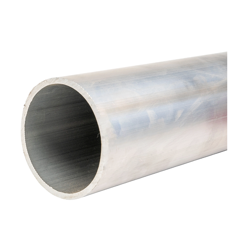
Ultra-high Voltage Magnesium-Aluminum Alloy Tubular Bus Bar
2. Material Engineering and Alloy Options
The performance of a magnesium-aluminum alloy tubular bus bar depends heavily on alloy composition and manufacturing control. Aluminum provides low density, useful conductivity, and good corrosion resistance. Magnesium can improve strength and contribute to a favorable strength-to-weight ratio. Manganese, rare-earth elements, and heat-resistant alloying systems may further modify strength, thermal stability, corrosion behavior, and manufacturing performance.
Rather than using one universal material for every project, the product family provides several alloy options. This approach allows the conductor to be matched to the electrical and mechanical priorities of a specific application.
2.1 6063G Aluminum-Magnesium Alloy
6063G aluminum-magnesium alloy is suitable for applications requiring a balanced combination of conductivity, formability, surface quality, and mechanical performance. Its characteristics make it appropriate for tubular profiles produced through controlled hot working and cold drawing.
This alloy can be considered where the project requires a dependable general-purpose tubular conductor with good corrosion resistance and practical fabrication performance. It may be used in substation bus systems, power plant connections, industrial distribution equipment, and selected renewable energy applications.
2.2 LF21Y Aluminum-Manganese Alloy
LF21Y aluminum-manganese alloy is designed for applications where corrosion resistance, structural stability, and reliable processing are important. Manganese-containing aluminum alloys are often selected for their useful combination of strength and environmental durability.
This type of alloy is valuable in outdoor installations where the bus bar may be exposed to humidity, industrial contaminants, temperature cycling, or coastal conditions. Surface treatment and joint protection remain important, but the alloy provides a sound material base for long-term environmental performance.
2.3 6R05 Rare-Earth Aluminum Alloy
6R05 rare-earth aluminum alloy incorporates rare-earth alloying technology to improve selected performance characteristics. Rare-earth additions can contribute to grain refinement, microstructural control, and improved stability when the material is processed correctly.
This option is suitable for projects that require a higher level of mechanical reliability or enhanced performance under demanding operating conditions. It may be considered for long-span busbar arrangements, high-wind locations, high-vibration environments, and installations where the conductor must maintain stable properties over a broad temperature range.
2.4 2A14 Heat-Resistant Aluminum Alloy
2A14 heat-resistant aluminum alloy is intended for operating conditions involving elevated conductor temperatures and high mechanical demands. High-temperature performance is especially important when the system operates with large continuous currents, limited installation space, or significant temporary overload requirements.
Depending on the final design and applicable technical standards, heat-resistant aluminum alloy options can support working temperatures in the approximate range of 150°C to 200°C. The exact allowable temperature must be determined through engineering verification, insulation coordination, joint assessment, and the requirements of the complete busbar system.
3. Technical Advantages of the Tubular Design
The product’s advantages do not come from alloy selection alone. The tubular profile creates a structural form that is efficient, stable, and well suited to high-voltage electrical equipment.
3.1 High Strength-to-Weight Ratio
Aluminum alloy is substantially lighter than copper for an equivalent volume. By using a tubular cross-section, the design can place material efficiently away from the neutral axis, increasing bending stiffness without adding unnecessary mass near the center of the section.
This lower weight can simplify lifting, transportation, installation, and support design. It may also reduce the structural load transferred to insulators, steelwork, foundations, and equipment terminals. In large substations and long-span installations, the reduction in dead weight can provide meaningful system-level benefits.
3.2 Efficient Current Carrying
The conductor is designed for high-current transmission, with product configurations intended for demanding ultra-high voltage applications. The actual current rating depends on alloy type, tube dimensions, ambient conditions, installation orientation, ventilation, joint resistance, permissible temperature rise, and applicable standards.
Large tubular conductors can provide a substantial conductive area while maintaining an external geometry that supports electric-field control. This makes them suitable for bus systems that must carry high current between major pieces of power equipment.
3.3 Improved Heat Dissipation
Heat is generated in a conductor by electrical resistance. If heat cannot be removed efficiently, the conductor temperature rises, potentially affecting conductivity, mechanical properties, joints, insulation, and nearby equipment.
The tubular structure supports convective heat dissipation from the external surface. The large exposed surface area relative to conductor mass can assist thermal management, particularly in naturally ventilated outdoor installations. A properly engineered system can therefore maintain a controlled temperature rise while transmitting significant current.
3.4 Better Electric-Field Distribution
Ultra-high voltage conductors must be designed to limit corona discharge, radio interference, audible noise, and localized electric-field stress. Sharp edges, surface irregularities, and abrupt changes in geometry can intensify the electric field.
A round tubular bus bar with a carefully finished surface provides a more uniform external geometry than a rectangular conductor with exposed corners. When used with appropriate fittings, grading components, shielding measures, and support insulators, it can contribute to a more uniform electric-field distribution.
3.5 Long-Span Capability
The high bending resistance of a tubular section can allow greater support spacing than conventional flat or less structurally efficient conductors. The stated maximum support span for certain configurations may reach approximately eight meters, subject to tube dimensions, material grade, environmental loads, and engineering calculations.
Longer spans can reduce the number of support points, decrease installation complexity, and improve access within a substation. However, span selection should always be verified against deflection, vibration, wind, ice, short-circuit, and seismic requirements.
4. Manufacturing Process and Quality Control
High-voltage busbar performance depends on more than the nominal alloy designation. The quality of casting, hot working, heat treatment, drawing, machining, surface finishing, and final assembly directly affects conductivity, strength, dimensional stability, and service reliability.
4.1 Horizontal Hot-Top Casting
Horizontal hot-top casting is used to produce aluminum alloy stock with controlled solidification conditions. The process helps reduce contamination, improve material purity, and promote a more uniform internal microstructure.
Stable casting conditions are important because inclusions, porosity, segregation, and uneven grain structure can become sources of weakness during subsequent tube production. Careful control of melt temperature, alloy composition, casting speed, cooling conditions, and process cleanliness supports a more consistent starting billet.
Material verification begins before the casting process. Alloy additions must be weighed and controlled accurately, and samples may be analyzed to confirm chemical composition. Process records provide traceability for each production batch and help ensure that the material used in a finished bus bar meets the intended specification.
4.2 Transverse Piercing Hot Rolling
Transverse piercing hot rolling is used to create a hollow tubular form without relying on a longitudinal welded seam. A seamless structure avoids the potential weaknesses associated with weld seams, heat-affected zones, and weld-related dimensional variation.
During piercing and hot rolling, the billet is transformed into a tube through controlled deformation. Temperature, reduction ratio, rolling speed, mandrel conditions, and lubrication must be managed carefully. These variables influence wall thickness, roundness, surface finish, grain flow, and internal soundness.
A seamless tube is particularly useful for high-voltage equipment because it provides consistent continuity around the circumference. It also eliminates the need to evaluate a welded joint as a separate potential failure location.
4.3 Thermomechanical Treatment
Thermomechanical treatment combines controlled deformation and thermal processing to adjust the material’s microstructure and performance. The objective is to balance conductivity, strength, ductility, dimensional stability, and resistance to thermal exposure.
Incorrect heat treatment can reduce conductivity, create excessive residual stress, or produce inconsistent mechanical properties. For this reason, production parameters must be matched to the selected alloy and final product dimensions. Cooling rates, holding times, and furnace uniformity are all important factors.
4.4 Multipass Cold Drawing
Cold drawing provides precise control of the tube’s outside diameter, inside diameter, wall thickness, straightness, and surface quality. Multiple drawing passes are used when significant dimensional reduction or tight tolerances are required.
Between drawing passes, intermediate treatment may be necessary to manage work hardening and maintain the required balance of strength and ductility. Drawing dies must be maintained accurately, and process lubrication must be controlled to prevent surface damage.
Dimensional precision is important for several reasons. It supports reliable connection design, helps ensure consistent clearances, simplifies support and clamp installation, and provides predictable mechanical behavior across the complete busbar run.
4.5 Machining and Surface Treatment
Ends, connection areas, support locations, and special interfaces may require CNC machining or other precision finishing processes. Accurate machining helps control contact resistance and ensures that fittings, expansion joints, and terminals are installed correctly.
Surface treatment may include oxidation, protective finishing, or other methods selected according to the environmental and insulation requirements. In coastal, salt-fog, industrial, or high-humidity locations, surface protection helps reduce corrosion risks and preserve long-term appearance and performance.
4.6 Inspection and Testing
Manufacturing quality control should include chemical composition verification, dimensional inspection, visual examination, surface inspection, mechanical testing, electrical testing, and appropriate non-destructive evaluation. The precise test program depends on the product specification and project requirements.
Finished systems may also undergo high-voltage tests, insulation tests, mechanical verification, temperature-rise evaluation, and routine quality checks. Testing cooperation with independent third-party institutions can provide additional validation for safety and performance claims.
5. Electrical, Thermal, and Mechanical Performance
5.1 Conductivity and Transmission Efficiency
The product is designed to provide high conductivity and strong current-carrying capability. Certain product configurations are described as having conductivity of at least 60% IACS, although the final value depends on the alloy, temper, processing route, and applicable technical standard.
High conductivity reduces voltage drop and resistive losses. In long busbar runs and high-current connections, even small reductions in resistance can produce useful energy savings over the operating life of the equipment. Lower losses also reduce the thermal burden placed on the conductor and adjacent components.
5.2 Temperature Performance
Some alloy options are intended for high-temperature operation, with applicable working temperatures reaching approximately 150°C to 200°C under suitable design conditions. The permitted temperature is not determined by the conductor alone. It must also consider insulation materials, support components, terminal connections, enclosure effects, ambient temperature, solar radiation, and emergency operating requirements.
Heat-resistant alloys can be advantageous in systems that must handle high current without using an excessively large cross-section. However, high-temperature operation may influence expansion, joint pressure, surface oxidation, and the service life of neighboring materials. These factors should be included in thermal and mechanical calculations.
5.3 Tensile and Bending Strength
Depending on material grade and processing condition, tensile strength may fall within an approximate range of 180 to 250 MPa. This range is presented as a product reference rather than a universal value for every configuration. The applicable design value should be confirmed through a technical data sheet and project-specific testing.
High tensile and bending strength supports installation across longer spans and improves resistance to wind and vibration. The material must nevertheless retain sufficient ductility to tolerate handling, thermal expansion, installation adjustments, and service movements without cracking.
5.4 Vibration and Seismic Resistance
Wind-induced vibration, equipment vibration, switching events, and seismic activity can produce repeated mechanical loads. A tubular bus bar with an appropriate alloy, wall thickness, support arrangement, and connection design can maintain structural stability under these conditions.
Seismic performance is a system characteristic. It depends on the conductor, insulators, clamps, supports, flexible connectors, foundation, and equipment arrangement. The bus bar’s mechanical properties provide an important foundation, but the complete assembly must be evaluated according to the seismic requirements of the project.
6. Insulation Compatibility and Corona Control
The bus bar can be integrated with several insulation processes, including epoxy resin vacuum casting and PTFE wrapping. The appropriate method depends on voltage level, installation environment, mechanical requirements, maintenance philosophy, and the design of the complete busbar system.
6.1 Epoxy Resin Vacuum Casting
Vacuum casting helps reduce voids and improve the consistency of the insulating layer. It can provide strong mechanical support and good environmental protection when the resin system, curing cycle, conductor preparation, and mold design are properly controlled.
Surface preparation is essential. The conductor must be clean, dry, and appropriately treated to promote adhesion between the alloy and the insulation. Oxidation or other specialized surface treatments can help address bonding challenges and improve the stability of the interface.
6.2 PTFE Wrapping
PTFE wrapping can be selected where a flexible, chemically resistant, and thermally stable insulation approach is required. The wrapping process must control overlap, tension, thickness, edge treatment, and protection against mechanical damage.
For ultra-high voltage applications, insulation design must also consider partial discharge, creepage distance, clearances, moisture ingress, thermal cycling, and the interaction between insulation and support hardware.
6.3 Corona and Partial Discharge Considerations
Corona can cause energy loss, audible noise, radio interference, ozone generation, and long-term deterioration of nearby insulation. The smooth tubular surface, rounded geometry, complete shielding approach, and carefully designed fittings are intended to support a uniform electric field and limit corona activity.
Actual corona performance must be verified through the relevant type tests and project conditions. Surface damage, sharp connection edges, contamination, incorrect installation, and unsuitable accessories can all affect the final result.
7. Comparison with Conventional Busbar Solutions
Different busbar materials and profiles have different strengths. Copper offers very high conductivity but carries a significant weight penalty and may increase the structural demands placed on supports. Ordinary aluminum is lightweight and economical, but some applications may require higher mechanical strength, improved thermal capability, or more specialized corrosion performance.
| Busbar Type | Approximate Weight | Typical Strengths | Common Considerations | Indicative Voltage Application |
|---|---|---|---|---|
| Magnesium-aluminum alloy tubular bus bar | Approximately 8–12 kg/m for selected configurations | Low weight, high stiffness, good conductivity, tubular electric-field profile, high-temperature alloy options | Requires precise alloy selection, joint design, and project-specific testing | Suitable for selected 500 kV to 1,000 kV systems |
| Traditional copper bus bar | Approximately 25–30 kg/m for selected configurations | Very high conductivity, established use, broad industry familiarity | Higher weight, greater support load, higher transportation and handling demands | Widely used across many voltage levels, subject to design |
| Ordinary aluminum bus bar | Approximately 7–10 kg/m for selected configurations | Low density, economical material, good general conductivity | May provide lower mechanical or thermal performance than specialized alloys | Commonly used in medium- and high-voltage applications |
The values in the table are indicative and should not replace a certified product data sheet. Weight, loss, temperature rating, current capacity, and maximum voltage depend on cross-sectional dimensions, material condition, support arrangement, connection design, and applicable standards.
7.1 Advantages over Copper
The most visible advantage over copper is weight reduction. A lighter busbar can reduce the size of support structures and simplify lifting and installation. It can also reduce the mechanical load imposed on insulators and connection points.
Aluminum alloys may also offer lower material and transportation costs in some projects. The tubular configuration further improves the relationship between stiffness and mass. However, copper remains a strong choice where maximum conductivity in a compact cross-section is the primary objective, so the final decision should consider total installed cost rather than material price alone.
7.2 Advantages over Ordinary Aluminum
Compared with ordinary aluminum bus bars, specialized magnesium-aluminum, manganese-aluminum, rare-earth aluminum, and heat-resistant aluminum options can offer improved mechanical performance, better temperature capability, or greater suitability for long-span and harsh-environment installations.
The production process also provides an advantage. Seamless tube production, thermomechanical control, and cold drawing can deliver a more precise and structurally consistent product than a basic extruded or less tightly controlled conductor profile.
7.3 Advantages over Welded Tubular Conductors
A seamless tubular conductor avoids a longitudinal weld seam. This reduces the need to manage weld-related discontinuities, heat-affected zones, and seam-specific inspection requirements. A continuous tubular wall can provide more uniform mechanical and electrical characteristics around the circumference.
Seamless production does not eliminate the need for inspection. Casting quality, piercing quality, drawing quality, surface condition, and end machining must all be controlled. Nevertheless, removing a welded seam can simplify the structural reliability assessment of the conductor.
8. Application Scenarios
8.1 Ultra-High Voltage Substations
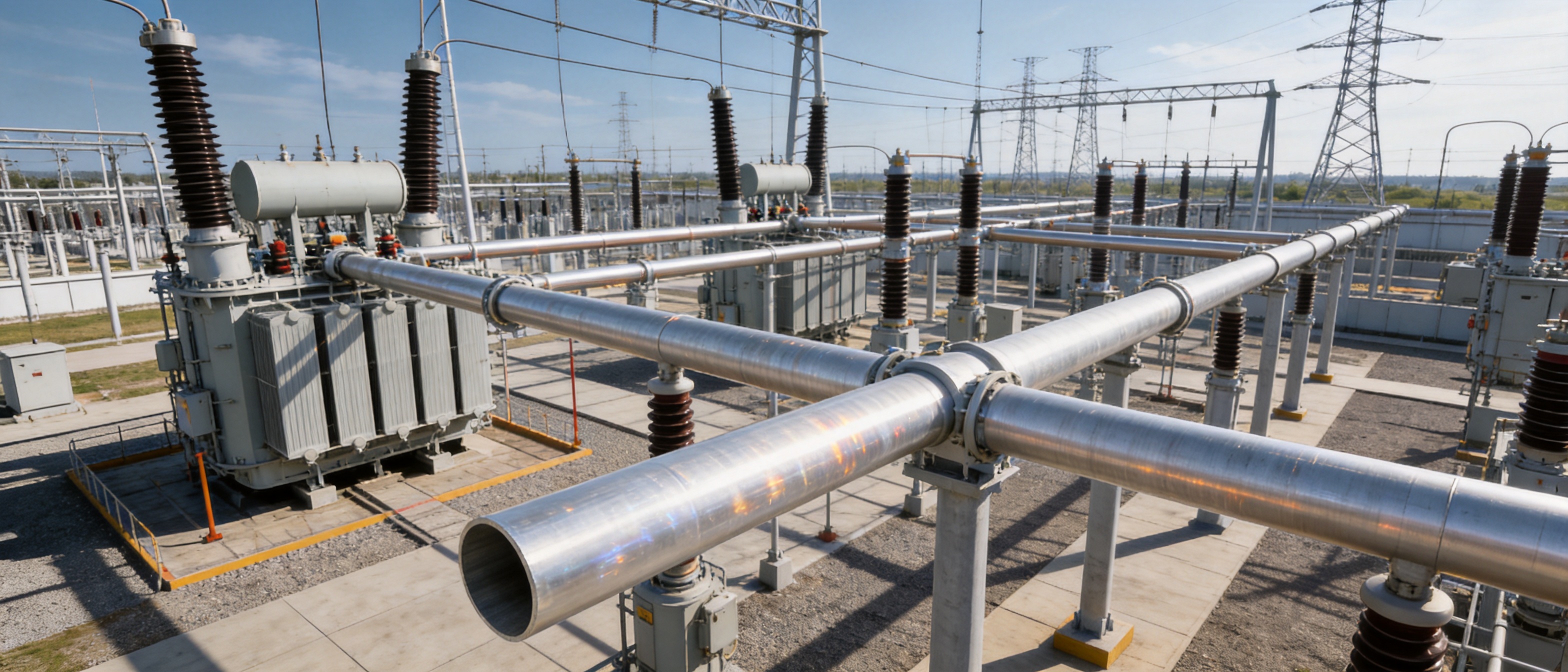
In substations rated at 500 kV and above, the tubular bus bar can be used for connections between transformers, circuit breakers, disconnectors, reactors, and other major equipment. Its high current capability and smooth external profile support the electrical and mechanical requirements of large outdoor switchyards.
Substation planning often requires long, straight conductor runs with carefully controlled clearances. The tube’s stiffness and dimensional accuracy can simplify support layout and help maintain stable geometry between equipment terminals.
8.2 Hydropower and Thermal Power Plants
Power plants must transfer large generator outputs with low losses and reliable mechanical support. The bus bar can serve as a connection between generator equipment, step-up transformers, and grid-side switchgear.
In these installations, the selection of alloy and insulation system should reflect local ambient conditions, generator output, short-circuit level, vibration environment, maintenance access, and the thermal profile of the connection route.
8.3 Wind Power Facilities
Wind power installations can experience vibration, rapid load variation, outdoor exposure, and difficult access conditions. Tubular bus bars may be used in collection systems, substations, transformer connections, and selected internal or external high-current routes.
For wind farms located offshore or near coastal areas, corrosion protection and sealing are especially important. Salt fog, humidity, wind-driven contaminants, and temperature changes can accelerate deterioration if the conductor surface and connection points are not properly protected.
8.4 Photovoltaic Power Stations
Large photovoltaic plants require reliable collection and transmission infrastructure. Aluminum alloy tubular bus bars can be considered for high-current connections between transformer stations, collection equipment, and higher-voltage grid interfaces.
Solar installations may experience intense solar radiation and significant daily temperature cycling. Thermal expansion, outdoor corrosion, UV exposure, and maintenance access should therefore be considered when selecting the alloy, insulation, support, and surface treatment.
8.5 Industrial Power Distribution
Metallurgy, chemical processing, manufacturing, and other energy-intensive industries require high-current distribution systems that can operate under demanding conditions. The tubular bus bar can be applied where high load, compact routing, mechanical strength, and operational reliability are required.
Industrial environments may involve corrosive gases, dust, heat, vibration, or restricted installation space. The selected surface treatment and insulation design should be matched to the specific contaminants and operating temperature of the facility.
8.6 Rail Transportation
Rail transit facilities require dependable power supply systems that can tolerate vibration and limited maintenance access. Lightweight, high-strength tubular conductors may be used in substations, traction power facilities, and other high-current distribution applications.
Because railway projects often have strict space, clearance, fire safety, and electromagnetic compatibility requirements, the busbar system should be engineered together with the supporting insulation and protection equipment.
8.7 High-Altitude and Specialized Facilities
High-altitude power stations may experience reduced air density, strong ultraviolet radiation, large temperature differences, wind, and difficult transportation conditions. These factors can affect insulation coordination, corona behavior, cooling, and mechanical loading.
The lightweight nature of the aluminum alloy tubular conductor can support transportation and installation planning in locations where access is difficult. The final design must nevertheless include altitude correction, insulation coordination, structural verification, and environmental protection.
9. Environmental Durability and Service Life
With suitable anti-corrosion treatment and normal operating conditions, the service life of the product can reach approximately 30 to 40 years. Actual service life depends on material selection, coating or surface treatment, installation quality, inspection, maintenance, environmental exposure, and the performance of joints and support components.
9.1 Corrosion Resistance
Aluminum alloys naturally form a protective oxide layer, but additional treatment may be required in salt-fog, industrial, coastal, or chemically aggressive environments. Corrosion protection should cover not only the main tube but also machined ends, joints, clamps, fasteners, transition areas, and locations where moisture can collect.
Material compatibility is also important. Contact between dissimilar metals can create galvanic corrosion under humid conditions. Appropriate transition components, surface protection, and joint design help reduce this risk.
9.2 Ice and Snow Conditions
Ice accumulation increases conductor weight and wind loading. A surface treatment intended to limit ice adhesion may help reduce the severity of ice formation, but the busbar supports and structure must still be designed for the governing ice and wind conditions.
In cold regions, the material must retain adequate toughness and mechanical performance at low temperatures. Product descriptions indicate operating suitability across a broad temperature range, including conditions approaching -40°C, subject to the selected alloy and system design.
9.3 Seismic and Wind Exposure
For high-wind or seismic regions, engineers should evaluate conductor deflection, natural frequency, support spacing, flexible connections, and relative movement between connected equipment. A strong tubular conductor can contribute to system stability, but rigidly connecting equipment that moves differently during an earthquake may increase stress.
Seismic design should therefore include flexible links, support insulator strength, foundation behavior, and equipment anchoring. The busbar should be treated as part of an integrated structural system rather than as an isolated component.
10. Engineering Selection Guide
10.1 Define the Electrical Parameters
The first step is to establish rated voltage, continuous current, short-circuit current, frequency, insulation level, temperature rise, and system grounding requirements. These parameters determine the conductor size, insulation arrangement, clearances, fittings, and test program.
The project should also identify whether the busbar will be installed indoors or outdoors, whether it will be insulated or bare, and whether it will operate in an enclosed, ventilated, or naturally cooled configuration.
10.2 Select the Alloy
Choose the alloy according to the relative importance of conductivity, strength, heat resistance, corrosion resistance, formability, and cost. A general-purpose aluminum-magnesium alloy may be suitable for balanced requirements, while rare-earth or heat-resistant grades may be preferred for high mechanical or thermal demands.
Alloy selection should be made together with the required temper and processing condition. The same nominal alloy can exhibit different performance depending on heat treatment, drawing reduction, aging, and final manufacturing controls.
10.3 Determine Dimensions and Span
Tube diameter and wall thickness influence current capacity, weight, bending stiffness, thermal performance, corona behavior, and connection design. Support spacing must be determined from structural calculations covering dead load, wind, ice, seismic effects, thermal expansion, and short-circuit forces.
Longer spans can reduce support quantities, but excessive span may increase deflection and vibration. A balanced design should optimize the complete installed cost and operating reliability rather than focusing only on the longest possible span.
10.4 Confirm Insulation and Surface Treatment
The insulation system should be selected according to voltage level, environmental conditions, thermal requirements, mechanical loads, maintenance strategy, and fire or chemical resistance requirements. The conductor surface must be prepared to achieve reliable adhesion or contact performance.
For outdoor applications, confirm protection against moisture, salt spray, ultraviolet exposure, pollution, and temperature cycling. For indoor industrial applications, consider chemical vapors, conductive dust, heat, and cleaning procedures.
10.5 Review Connections and Accessories
Busbar joints, terminals, clamps, expansion devices, shields, support insulators, and grounding arrangements can determine the reliability of the complete installation. Connection resistance should be controlled, and joints should accommodate thermal expansion without creating excessive mechanical stress.
Accessories should be compatible with the alloy and surface treatment. Their current rating, mechanical strength, insulation level, corrosion behavior, and installation tolerances should be verified together with the main conductor.
11. Manufacturing and Engineering Strengths
A reliable busbar supplier must provide more than a metal tube. The supplier should be capable of converting project requirements into a coordinated product design, manufacturing plan, inspection program, and installation solution.
The manufacturing capabilities associated with this product include vacuum casting technology, CNC machining, automated assembly, precision tube production, and standardized inspection. These capabilities support consistent quality from raw material preparation through final delivery.
Engineering personnel with experience in high- and low-voltage busbar systems can assist with alloy selection, conductor dimensions, insulation coordination, support spacing, connection design, and environmental protection. This engineering approach is particularly valuable for customized projects where standard catalog dimensions are not sufficient.
A strict quality management process should maintain traceability for raw materials, production batches, heat treatment, drawing operations, machining, assembly, testing, and final inspection. Documentation allows project owners and engineering contractors to verify that the supplied equipment corresponds to the approved technical specification.
Products operating across multiple provinces and industrial sectors provide practical experience in varied environments, including power generation, substations, wind energy, industrial manufacturing, rail transit, and commercial facilities. Such application experience can improve the ability to anticipate installation challenges and recommend suitable configurations.
12. Installation and Maintenance Considerations
Before installation, the busbar should be inspected for transportation damage, deformation, contamination, moisture, and surface defects. Lifting equipment must be selected according to the tube length and weight, and the conductor should be supported at appropriate points to prevent bending.
Connection surfaces should be cleaned and prepared according to the approved installation procedure. Excessive force, uncontrolled drilling, unapproved welding, or improper clamping can alter the conductor’s mechanical and electrical performance.
During installation, alignment should be checked carefully. Misalignment can transfer unwanted forces to terminals and insulators. Expansion joints or flexible connections should be installed where required by the thermal movement calculation.
Routine maintenance may include visual inspection, temperature monitoring, infrared inspection of joints, examination of surface treatment, checking of support hardware, and review of insulation condition. In corrosive environments, inspection intervals may need to be shortened.
Any evidence of overheating, discoloration, corrosion, cracking, abnormal vibration, discharge, or loose hardware should be investigated promptly. Maintenance procedures should follow the project’s electrical safety rules and the recommendations of the equipment supplier.
13. Q&A: Ultra-High Voltage Magnesium-Aluminum Alloy Tubular Bus Bar
Q1: What is an ultra-high voltage magnesium-aluminum alloy tubular bus bar?
It is a hollow conductive tube made from a specialized aluminum alloy containing magnesium or other controlled alloying elements. It is designed for high-current transmission and distribution in high-voltage and ultra-high voltage power systems.
Q2: Which voltage levels can the product serve?
The product family is intended for applications including 220 kV, 500 kV, 750 kV, ±800 kV, and 1,000 kV systems. The applicable voltage depends on the complete insulation, support, clearance, corona-control, and testing design.
Q3: What alloys are available?
Available material options include 6063G aluminum-magnesium alloy, LF21Y aluminum-manganese alloy, 6R05 rare-earth aluminum alloy, and 2A14 heat-resistant aluminum alloy. The best choice depends on current, temperature, mechanical loading, corrosion exposure, and project specifications.
Q4: Why use a tubular conductor instead of a flat bus bar?
A tubular conductor offers high bending stiffness, a favorable strength-to-weight ratio, a smooth circular external surface, and useful heat-dissipation characteristics. It can also support longer spans and contribute to more uniform electric-field distribution.
Q5: Is the product lighter than a copper bus bar?
Selected configurations are significantly lighter than comparable copper conductors. Indicative product data places some tubular aluminum alloy configurations at approximately 8–12 kg/m, while selected copper busbar configurations may be approximately 25–30 kg/m. Exact values depend on dimensions and design requirements.
Q6: What is the conductivity of the alloy tubular bus bar?
Some product configurations are specified at conductivity of at least 60% IACS. The final conductivity must be confirmed for the selected alloy, temper, dimensions, and applicable technical standard.
Q7: Can it operate at high temperatures?
Heat-resistant alloy options are designed for elevated-temperature service, with certain configurations intended for operating temperatures of approximately 150°C to 200°C. The complete system rating must also consider insulation, joints, supports, terminals, and environmental conditions.
Q8: Is the bus bar suitable for outdoor installations?
Yes. With suitable surface treatment, insulation, sealing, and accessory selection, it can be used in outdoor substations, wind power facilities, photovoltaic plants, power stations, and industrial installations. Salt spray, pollution, ice, wind, and ultraviolet exposure should be evaluated during design.
Q9: How is the seamless tube manufactured?
The manufacturing route includes horizontal hot-top casting followed by transverse piercing hot rolling. Subsequent thermomechanical treatment and multipass cold drawing control the microstructure, dimensions, straightness, and surface quality.
Q10: What insulation processes are compatible with the conductor?
The conductor can be integrated with insulation methods such as epoxy resin vacuum casting and PTFE wrapping. Surface preparation and treatment are important to achieve reliable adhesion and long-term insulation performance.
Q11: What is the maximum support span?
Some configurations may achieve a support span of up to approximately eight meters. The actual allowable span must be calculated according to conductor dimensions, alloy, wind, ice, seismic loads, short-circuit forces, deflection limits, and support hardware.
Q12: What is the expected service life?
With suitable anti-corrosion treatment and normal operating conditions, the expected service life may reach approximately 30 to 40 years. Actual service life depends on environment, installation quality, maintenance, joints, insulation, and system loading.
Q13: Can the product be customized?
Customization may include alloy selection, tube diameter, wall thickness, length, surface treatment, insulation method, connection arrangement, support accessories, and packaging. Technical parameters should be finalized through engineering review before production.
Q14: What documentation should be requested before purchase?
Project documentation may include material certificates, dimensional reports, mechanical and electrical test results, type-test reports where applicable, insulation test records, routine inspection records, installation instructions, and quality traceability documents.
14. Conclusion
The ultra-high voltage magnesium-aluminum alloy tubular bus bar is a specialized solution for modern power transmission and distribution systems. Its combination of low weight, high structural efficiency, strong conductivity, thermal capability, corrosion resistance, and tubular electric-field geometry makes it suitable for demanding installations from high-voltage substations to ultra-high voltage transmission facilities.
Its performance is supported by a complete manufacturing route rather than by alloy composition alone. Horizontal hot-top casting improves material consistency, transverse piercing hot rolling creates a seamless tube, thermomechanical treatment adjusts the microstructure, and multipass cold drawing provides accurate dimensions and surface quality. CNC machining, surface treatment, insulation integration, automated assembly, and standardized testing further support product reliability.
Compared with conventional copper bus bars, the product can reduce structural and handling loads. Compared with ordinary aluminum conductors, specialized alloy grades and precision processing can provide improved strength, temperature performance, environmental durability, and long-span capability. These advantages may contribute to lower installation complexity, more efficient use of support structures, and reliable operation over a long service period.
Successful application requires system-level engineering. Alloy, dimensions, insulation, supports, joints, expansion arrangements, surface protection, and testing must all be selected according to the actual electrical and environmental conditions. When these factors are properly coordinated, the magnesium-aluminum alloy tubular bus bar can provide a robust and efficient conductive platform for the next generation of high-capacity power infrastructure.
References
1. IEC 62271 Series, High-Voltage Switchgear and Controlgear.
2. IEC 60865 Series, Short-Circuit Currents: Calculation of Effects.
3. IEC 60071 Series, Insulation Coordination.
4. ASTM B209, Standard Specification for Aluminum and Aluminum-Alloy Sheet and Plate.
5. ASTM B221, Standard Specification for Aluminum and Aluminum-Alloy Extruded Bars, Rods, Wire, Profiles, and Tubes.
6. Aluminum Association, Aluminum Standards and Data.
7. International Electrotechnical Commission, Guidance on High-Voltage Testing and Insulation Performance.
8. Technical documentation for aluminum-magnesium, aluminum-manganese, rare-earth aluminum, and heat-resistant aluminum alloy conductors.
9. Power transmission and substation engineering manuals covering busbar design, thermal rating, electric-field control, and mechanical loading.
10. Manufacturer quality-control procedures for casting, seamless tube production, cold drawing, machining, insulation, and final electrical testing.
Product: Ultra-high Voltage Magnesium-Aluminum Alloy Tubular Bus Bar




-
 +86-180 3625 3000
-
 admin@wpbusbar.com
-
 No. 8, Yanjin Road, Chengxi Industrial Park, Shanyang Town, Baoying County, Yangzhou City, Jiangsu Province, China
Copyright © Jiangsu Wopeng Power Technology Co., Ltd.
All Rights Reserved.
 Custom Insulated Bus Bar Manufacturer
Tubular Busbar System Factory