

 EN
EN

 English
 русский
 Français
 Español
 عربى
عربى
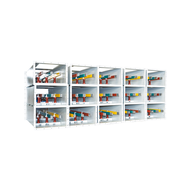


Advanced Post Insulator Solutions for Insulated Tubular Busbar Systems
Content
- 1 1. The Function of Post Insulators in Electrical Systems
- 2 2. Integration with Fully Insulated Tubular Busbar Systems
- 3 3. Advantages Compared with Conventional Busbar Support Solutions
- 4 4. Technical Performance of the Post Insulator and Busbar Support System
- 5 5. Material Options and Insulation Characteristics
- 6 6. Advanced Manufacturing Processes
- 7 7. Quality Control and Testing Strengths
- 8 8. Installation Benefits for Engineering Projects
- 9 9. Environmental Adaptability and Long-Term Reliability
- 10 10. Application Areas
- 11 11. Competitive Advantages of the Solution
- 12 12. Service Life and Maintenance Strategy
- 13 13. Customization and OEM Engineering Capability
- 14 14. Selection Guidelines for Post Insulators and Tubular Busbar Supports
- 15 15. Q&A Section
- 15.1 Q1: What is a post insulator used for?
- 15.2 Q2: Can a post insulator be eliminated in an insulated tubular busbar system?
- 15.3 Q3: Why is a tubular busbar stronger than a rectangular busbar?
- 15.4 Q4: What span can an insulated tubular busbar achieve?
- 15.5 Q5: Is the system suitable for seismic areas?
- 15.6 Q6: Can the product be used in polluted environments?
- 15.7 Q7: What materials are used for post insulators?
- 15.8 Q8: What are the main advantages over competitor systems?
- 15.9 Q9: What industries use these solutions?
- 15.10 Q10: How should a customer select the right solution?
- 16 16. Conclusion
- 17 References
- 18 Product: Post Insulator
Post insulators are essential components in electrical power systems, traditionally used to support energized conductors, bus bars, switchgear connections, and equipment terminals while maintaining reliable electrical isolation from grounded structures. In modern medium- and low-voltage power distribution systems, however, the role of the post insulator is evolving. With the development of fully insulated tubular busbar systems and aluminum alloy tubular busbars, traditional support concepts can be optimized, simplified, or partially replaced by integrated structural designs.
This article focuses on the post insulator as applied to insulated tubular busbar systems, especially in medium- and low-voltage electrical networks. It explains how post insulators function, how they interact with aluminum alloy tubular busbars, and why advanced insulated tubular busbar systems can reduce the number of post insulators, fittings, wall bushings, and structural foundations required in a project. It also highlights the engineering advantages, manufacturing strengths, quality control methods, and application value offered by Jiangsu Wopeng Power Technology Co., Ltd. in the field of busbar systems and related electrical support solutions.
1. The Function of Post Insulators in Electrical Systems
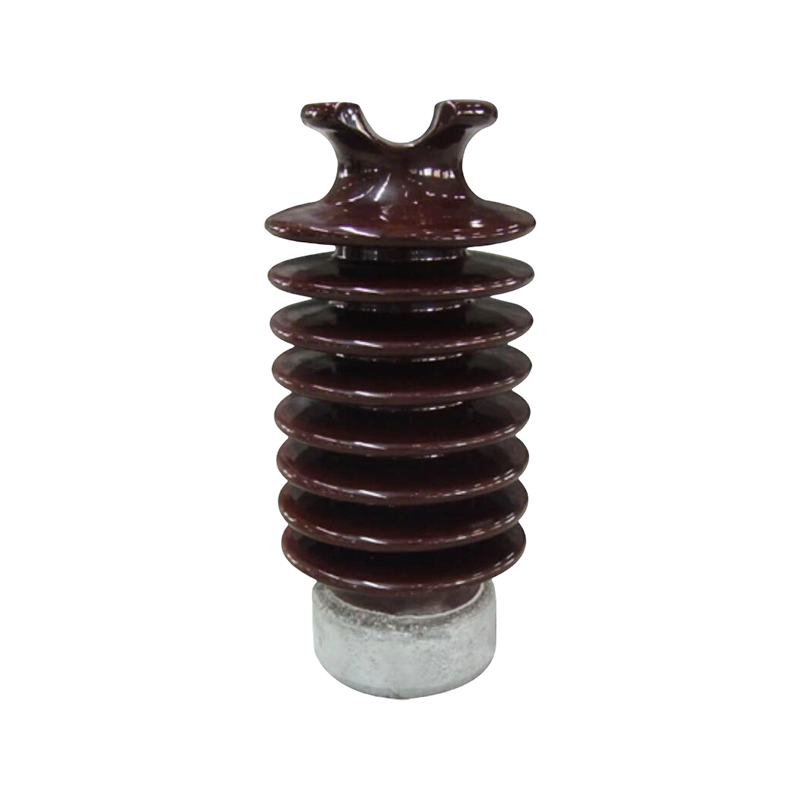
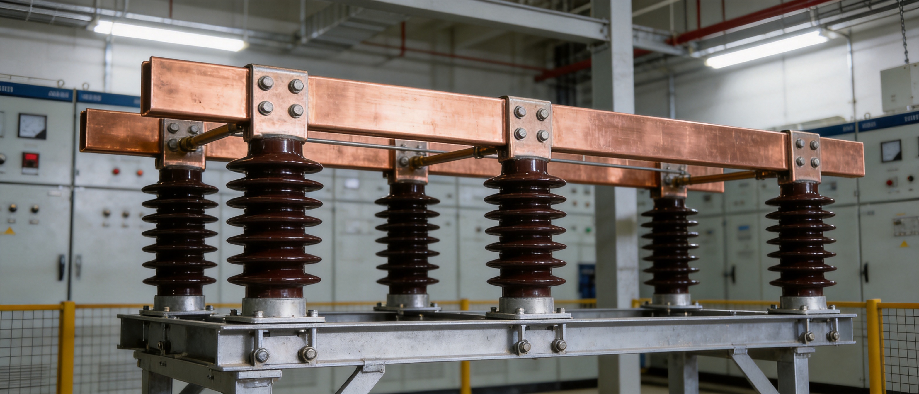
A post insulator is a rigid insulating support used to hold live electrical components at a safe distance from grounded metal structures, panels, cabinets, beams, or concrete foundations. It performs two critical functions at the same time: mechanical support and electrical insulation. Mechanically, it must withstand the weight of conductors and busbars as well as electrodynamic forces caused by short-circuit currents. Electrically, it must prevent leakage current, flashover, and breakdown under rated voltage, temporary overvoltage, polluted environments, and high humidity.
In substations, switchgear rooms, distribution cabinets, transformer stations, industrial power systems, and renewable energy facilities, post insulators are commonly used to support copper or aluminum busbars. They are especially important in medium-voltage and high-current power systems, where conductors are large, heavy, and exposed to strong electromagnetic forces during faults. A well-designed post insulator helps stabilize the entire electrical arrangement, keeping conductor spacing consistent and reducing the risk of phase-to-phase or phase-to-ground failure.
Traditional rectangular busbar systems rely heavily on post insulators. These systems often require multiple insulators, brackets, fittings, and support foundations at relatively short intervals. The installation process may involve civil construction, alignment adjustment, bolt fixing, insulation coordination, and repeated inspection. While this method is mature and widely used, it can increase material cost, installation time, maintenance workload, and potential failure points.
With insulated tubular busbar technology, the support philosophy becomes more efficient. The tubular busbar itself has higher mechanical strength than a rectangular busbar of comparable current capacity. When the busbar is fully insulated and structurally reinforced, it can be directly fixed to steel structures or concrete supports through dedicated brackets. As a result, some conventional post insulators can be eliminated or replaced by optimized support assemblies, reducing system complexity without compromising safety.
2. Integration with Fully Insulated Tubular Busbar Systems
The insulated tubular busbar system represents a significant improvement over traditional open rectangular busbar arrangements. Instead of using flat conductors exposed to the environment, the system uses round tubular conductors made from copper or aluminum alloy and covered with high-performance insulating materials. In many medium- and low-voltage applications, aluminum alloy tubular busbars offer an excellent balance of electrical conductivity, mechanical rigidity, weight reduction, thermal performance, and cost efficiency.
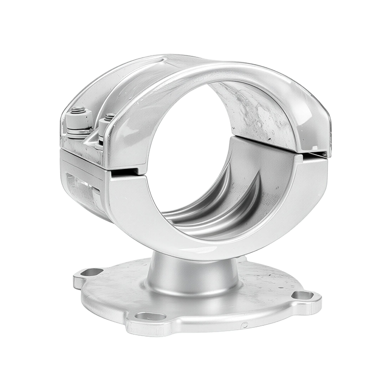
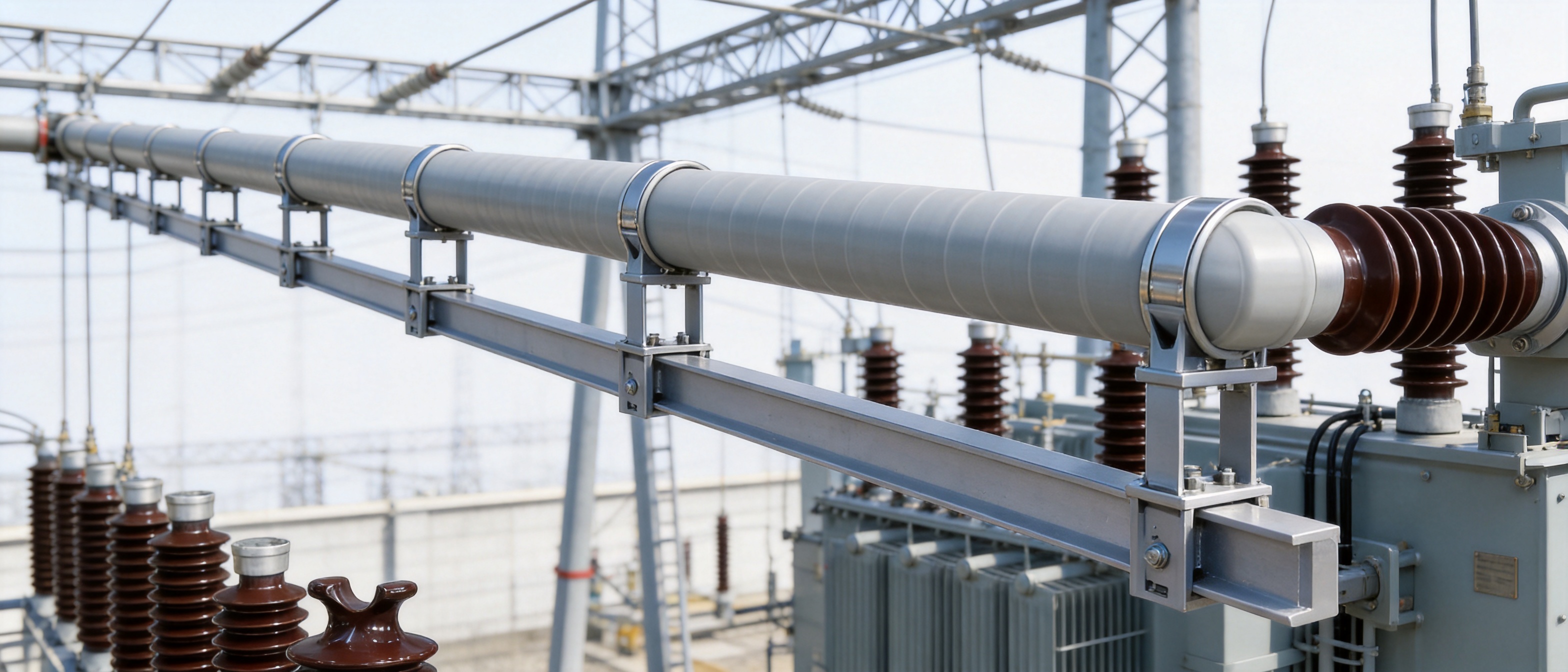
In an optimized insulated tubular busbar system, the busbar can be directly fixed to steel framework or concrete support structures. The support brackets are designed specifically for tubular profiles, allowing the busbar to remain stable under vibration, thermal expansion, mechanical load, and short-circuit stress. This arrangement can reduce the number of post insulators required in the installation and simplify the entire busbar route.
For example, under a short-circuit current of 50 kA, a tubular busbar with a specification of Φ100×6 mm can achieve a suspended span of up to 9 meters. When supported by dedicated busbar brackets, the span can reach up to 13 meters. This is a major advantage compared with many traditional rectangular busbar systems, which require closer support spacing and more insulator points. Longer spans mean fewer supports, fewer fittings, fewer civil foundations, and more flexible system layout.
The system can be directly connected to high-voltage rooms, indoor current-limiting reactors, or 10 kV switchgear cabinets. By reducing the need for wall bushings, post insulators, and auxiliary fittings, it lowers construction difficulty and improves operational reliability. In projects where space is limited, where seismic requirements are strict, or where maintenance access is difficult, this integrated design provides clear engineering value.
3. Advantages Compared with Conventional Busbar Support Solutions
Compared with conventional rectangular busbar systems supported by multiple post insulators, insulated tubular busbar systems provide several competitive advantages. These advantages are not only related to the busbar conductor itself but also to the overall system structure, installation method, insulation performance, and long-term maintenance cost.
3.1 Simplified Structure
Traditional busbar arrangements often require a combination of post insulators, wall bushings, clamps, support beams, fittings, and grounding structures. Each component must be correctly selected, installed, and maintained. Every connection point or support point introduces a potential location for mechanical loosening, contamination accumulation, insulation aging, or flashover risk.
By contrast, an insulated tubular busbar system adopts a more integrated structure. The busbar is supported by dedicated brackets and can be fixed directly to steel or concrete structures. In many cases, wall bushings and numerous post insulators are no longer necessary. This simplified structure reduces installation steps, minimizes component interfaces, and improves overall system reliability.
3.2 Higher Mechanical Strength
The tubular shape provides excellent mechanical performance. A circular cross-section offers superior resistance to bending, torsion, and vibration compared with a flat rectangular profile. The allowable stress of an insulated tubular busbar can be approximately four times that of a traditional rectangular busbar. This allows the busbar to withstand strong electrodynamic forces during short-circuit events.
Under a 50 kA short-circuit current, the ability of a Φ100×6 mm tubular busbar to reach long suspended spans demonstrates its structural advantage. Competitor systems based on conventional rectangular busbars may require more frequent support points and more insulators to achieve similar stability. This increases cost and complexity. The tubular design therefore provides a practical and measurable advantage in high-current power transmission applications.
3.3 Improved Vibration Resistance
Power systems are subject to vibration from transformers, reactors, mechanical equipment, switching operations, wind, seismic movement, and electromagnetic forces. Vibration can loosen fasteners, fatigue support components, and reduce insulation reliability. The insulated tubular busbar system has strong vibration resistance because of its rigid profile, optimized bracket support, and reduced number of separate components.
The post insulator design used in such systems can meet demanding seismic conditions. It is designed to withstand horizontal acceleration of 0.20 g, vertical acceleration of 0.15 g, a vibration frequency of 20 Hz, and three sine wave cycles. With a safety factor greater than 1.67, the system can maintain normal operation under simultaneous seismic and short-circuit conditions. This is particularly important for substations, power plants, industrial parks, and infrastructure projects located in seismic regions.
3.4 Reduced Maintenance Requirements
Traditional post insulators, especially outdoor porcelain or ceramic types, require periodic inspection and cleaning. Pollution, salt mist, industrial dust, moisture, and biological contamination can accumulate on the surface and reduce insulation performance. Maintenance teams may need to perform contamination cleaning, crack detection, mechanical tightening, and electrical testing.
Fully insulated tubular busbar systems substantially reduce exposure of energized conductors. The enclosed insulation design helps protect the conductor from external contaminants and accidental contact. Since the number of post insulators and open support points can be reduced, the maintenance workload is also lowered. This advantage becomes more valuable in coastal areas, industrial pollution zones, high-altitude locations, and facilities where shutdown time is expensive.
4. Technical Performance of the Post Insulator and Busbar Support System
A reliable post insulator or integrated support system must be evaluated through electrical, mechanical, environmental, and installation performance. It must maintain insulation integrity over decades of operation while supporting live components safely under normal and fault conditions.
The system described here is suitable for altitudes up to 4,000 meters. This is important because air insulation strength decreases as altitude increases. Electrical equipment used at high altitude must be carefully designed to maintain adequate insulation margins. The system also considers heavy pollution conditions, with a pollution severity class up to Class V. For outdoor terminals, creepage extenders can be installed to increase the total creepage distance to not less than 680 mm, helping prevent pollution flashover.
The design creepage distance ratio can reach 31 mm/kV, which supports reliable operation in challenging environments such as coastal regions, chemical plants, cement plants, mining areas, metallurgical plants, and industrial zones with airborne dust or corrosive contaminants. When combined with hydrophobic insulation materials and optimized surface geometry, the risk of tracking, leakage current, and flashover is reduced.
Mechanically, the post insulator or bracket-supported tubular busbar arrangement must withstand bending forces, tensile forces, vibration, thermal expansion, and electrodynamic forces during short circuits. Standard post insulator designs may support bending loads from 2 kN to 20 kN depending on size, voltage level, material, and structural design. For tubular busbar systems, the conductor profile and support spacing are engineered together to ensure stable performance.
| Performance Aspect | Traditional Rectangular Busbar with Multiple Post Insulators | Insulated Tubular Busbar with Optimized Support |
|---|---|---|
| Support Structure | Requires frequent post insulators, fittings, and foundations | Uses dedicated brackets and may reduce or replace post insulators |
| Mechanical Strength | Lower bending and torsional resistance | High rigidity; allowable stress can be four times higher |
| Span Capability | Shorter support intervals are usually required | Suspended span up to 9 m; bracket-supported span up to 13 m for Φ100×6 mm under 50 kA |
| Installation Complexity | More alignment, fixing, and civil work | Simplified exposed installation with standardized brackets |
| Maintenance | Requires regular cleaning and inspection of many insulators | Reduced open insulation points and lower maintenance frequency |
| Environmental Adaptability | Depends heavily on insulator material and creepage design | Designed for high altitude, heavy pollution, and outdoor terminal creepage extension |
5. Material Options and Insulation Characteristics
Post insulators can be manufactured from several types of insulating materials, including electrical porcelain, toughened glass, epoxy resin, and composite polymer materials such as silicone rubber. Each material has its own advantages. Porcelain has excellent compressive strength, weather resistance, and long service history. Toughened glass provides high dielectric strength and visible failure characteristics. Composite materials offer light weight, excellent hydrophobicity, high resistance to pollution flashover, and improved impact resistance.
In modern medium- and low-voltage busbar applications, material selection is based on voltage level, environmental conditions, mechanical load, installation method, and maintenance strategy. For indoor switchgear and compact electrical rooms, epoxy resin and composite insulation are often preferred because of their compact size, stable insulation performance, and ease of molding. For outdoor substations or heavy pollution environments, silicone rubber composite insulators may provide excellent anti-pollution behavior due to hydrophobic surface properties.
For insulated tubular busbars, the insulation system is just as important as the conductor. Vacuum casting, epoxy resin insulation, heat-resistant layers, shielding structures, and surface protection may be used depending on the product category and voltage level. A well-designed insulation layer must bond firmly to the conductor, resist partial discharge, withstand thermal cycling, and maintain dielectric properties under long-term electrical stress.
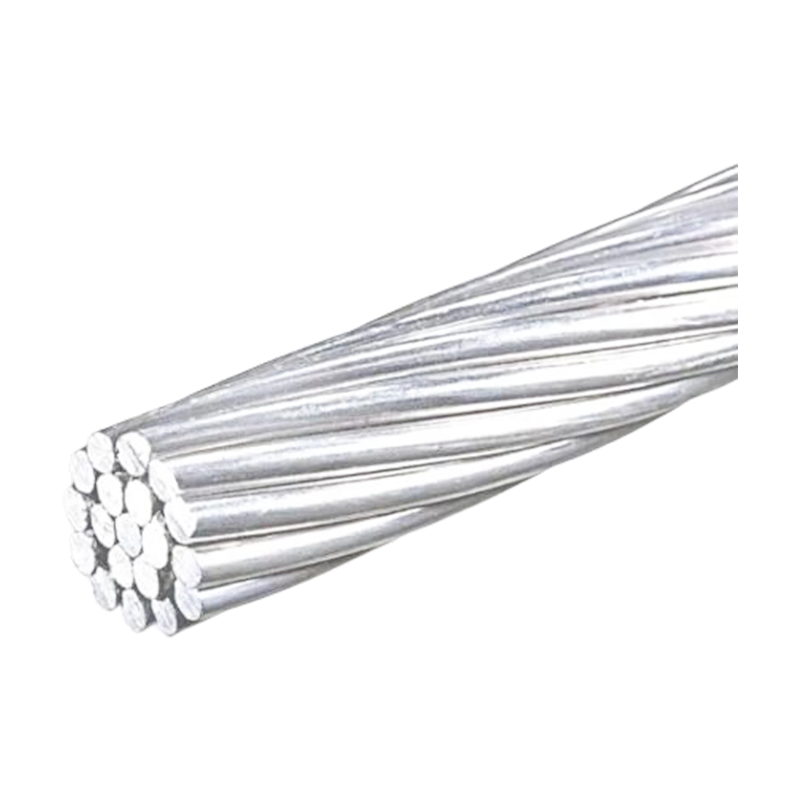
Aluminum alloy tubular busbars provide an efficient conductor solution. Aluminum alloy offers lower density than copper, reducing weight and easing installation. The tubular form increases heat dissipation surface area and improves current-carrying capability. When properly designed, aluminum alloy tubular busbars deliver stable performance in high-current power transmission while reducing material cost and structural load.
6. Advanced Manufacturing Processes
Jiangsu Wopeng Power Technology Co., Ltd. specializes in the development and manufacturing of high- and low-voltage busbar systems. Its production capabilities support product categories such as 35 kV epoxy resin vacuum-cast tubular busbars, low-voltage cast resin busways, copper and aluminum tubular busbars, wind power tubular busbars, compact busbar systems, and sliding contact line systems. These capabilities provide a strong manufacturing foundation for reliable post insulator integration and optimized busbar support solutions.
Advanced manufacturing begins with conductor preparation. Aluminum alloy or copper tubular conductors must be selected according to electrical conductivity, mechanical strength, wall thickness, dimensional tolerance, and surface quality. Tube cutting, shaping, drilling, CNC machining, and end processing must be carried out precisely to ensure accurate fit with brackets, terminals, switchgear interfaces, and connection accessories.
Surface treatment is another critical step. Before insulation or assembly, the conductor surface must be cleaned, prepared, and inspected. Contaminants such as oil, oxide, dust, or moisture can reduce insulation bonding strength. Controlled surface treatment improves adhesion and ensures long-term dielectric stability.
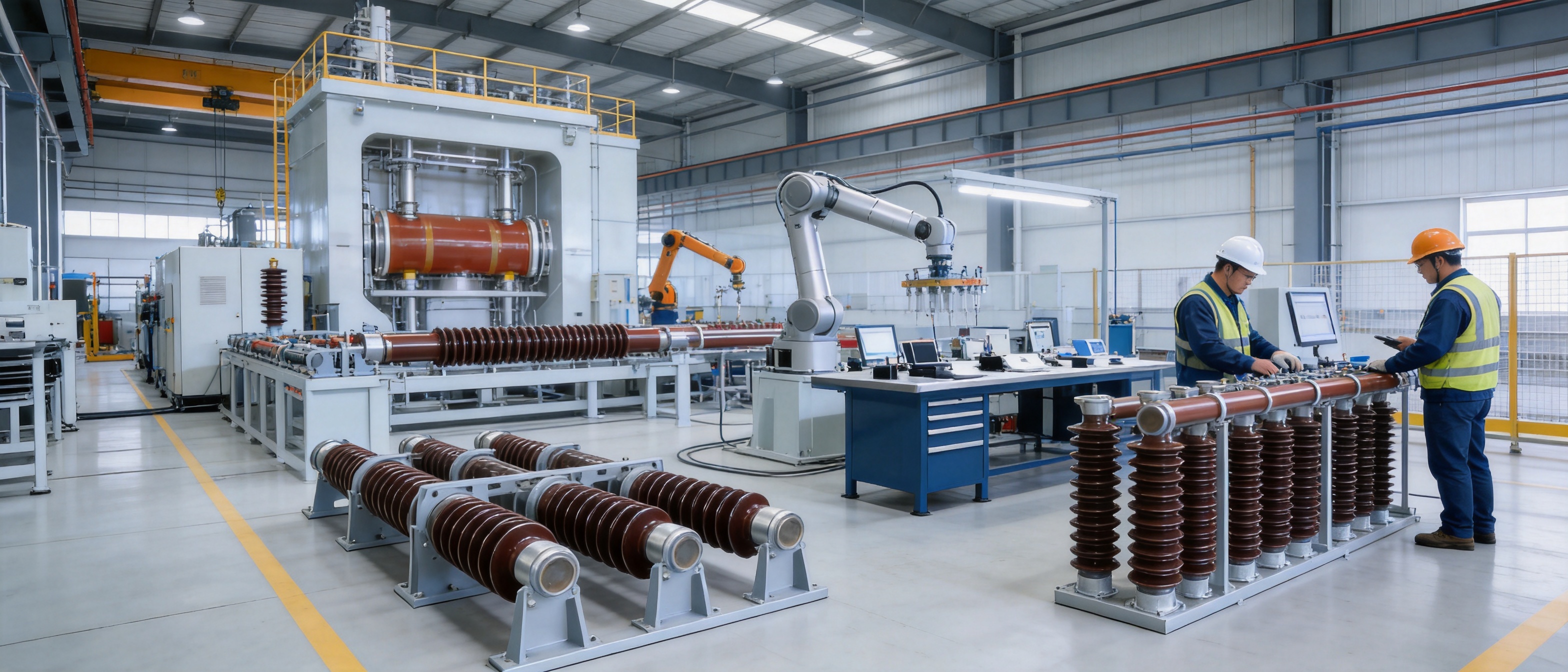
Vacuum casting technology is especially important for epoxy resin insulated tubular busbars. Under vacuum conditions, air bubbles and voids are removed from the insulation material before curing. This reduces the risk of partial discharge, insulation aging, and internal breakdown. A uniform casting process ensures stable wall thickness, consistent insulation performance, and reliable mechanical bonding between insulation and conductor.
CNC machining equipment helps maintain product consistency. Bracket interfaces, connection holes, terminal surfaces, and assembly dimensions must be accurate. Precision machining reduces installation errors, improves contact reliability, and ensures compatibility with switchgear cabinets, reactors, transformer terminals, and support structures. Automated or semi-automated assembly technologies further improve repeatability and reduce human error.
7. Quality Control and Testing Strengths
For power transmission products, quality control is not optional; it is fundamental. A busbar support system or post insulator must operate safely over many years, often in locations where failure can cause costly downtime, equipment damage, or safety hazards. Jiangsu Wopeng Power Technology Co., Ltd. uses standardized inspection processes, including high-voltage tests, insulation tests, mechanical verification, and routine quality checks.
High-voltage testing verifies dielectric withstand capability. The product must maintain insulation under specified voltage stress without flashover, puncture, or abnormal discharge. Insulation resistance testing confirms that leakage current remains within acceptable limits. In high-quality post insulator products, insulation resistance can remain extremely high, often above 1.0×10¹³ ohms depending on voltage class, material, and test conditions.
Mechanical verification is equally important. Tubular busbars and post insulator supports must withstand static load, bending load, vibration, and short-circuit electrodynamic force. Design calculations must be supported by testing or engineering validation. For seismic applications, the ability to withstand horizontal acceleration of 0.20 g and vertical acceleration of 0.15 g provides confidence for infrastructure projects in regions with earthquake risk.
Routine inspection covers dimensions, appearance, assembly quality, insulation surface condition, conductor continuity, contact quality, and packaging. Third-party testing collaboration provides independent validation of safety and performance. This is valuable for customers who require documented assurance for substations, industrial projects, rail transit facilities, wind power systems, and large commercial power distribution networks.
8. Installation Benefits for Engineering Projects
Installation efficiency is one of the most important advantages of optimized insulated tubular busbar systems. In traditional systems, project teams must install multiple post insulators, align busbars, adjust conductor spacing, construct support foundations, mount wall bushings, and verify each mechanical connection. This can be time-consuming, especially in large substations or complex industrial plants.
The insulated tubular busbar system uses an exposed installation method with dedicated support brackets. Bracket spacing is generally designed according to electrical clearance, mechanical load, thermal expansion, and site layout. A bracket spacing of at least 275 mm can be applied in relevant configurations, and fixed brackets must be installed for spans ranging from 6 to 13 meters. This standardized approach simplifies site work and reduces installation risk.
Because the busbar can be directly connected to high-voltage rooms, indoor current-limiting reactors, or 10 kV switchgear cabinets, system interfaces are more compact. Fewer post insulators and fittings mean fewer parts to transport, store, install, and inspect. This reduces project schedule pressure and helps contractors maintain consistent quality.
In addition, the tubular busbar’s high rigidity helps maintain alignment during installation. Rectangular busbars can deform more easily during handling or under mechanical stress. Tubular profiles are more stable, which helps preserve electrical clearance and improve the final appearance of the installation. For modern electrical rooms where safety, space, and visual order are important, this is a meaningful advantage.
9. Environmental Adaptability and Long-Term Reliability
Electrical systems are expected to operate reliably in a wide range of environments. Temperature variation, humidity, altitude, pollution, salt fog, dust, vibration, and chemical exposure can all affect insulation and mechanical components. A post insulator or busbar support system must therefore be designed not only for ideal laboratory conditions but also for real-world operating environments.
The described post insulator and insulated tubular busbar solution is suitable for altitudes up to 4,000 meters. At high altitude, reduced air density lowers dielectric strength, increasing the risk of flashover if insulation coordination is not properly designed. By considering creepage distance, insulation thickness, terminal design, and electrical clearance, the system can maintain safe operation in mountainous regions and high-altitude industrial projects.
For heavily polluted environments, the system can meet pollution severity class V requirements. A creepage distance ratio of 31 mm/kV helps reduce the risk of leakage current and flashover. Outdoor terminals can be equipped with creepage extenders, ensuring total creepage distance of not less than 680 mm. These features are particularly important for coastal substations, petrochemical facilities, steel plants, cement plants, ports, and mining operations.
Seismic adaptability is another important reliability factor. Electrical equipment must continue operating or remain safe during earthquakes. The design considers simultaneous seismic and short-circuit conditions, which is more demanding than considering either condition alone. With a safety factor greater than 1.67, the system provides a robust margin for critical power infrastructure.
10. Application Areas
Post insulators and insulated tubular busbar systems are used across many sectors of modern power distribution. In substations, they support high-current connections between switchgear, transformers, reactors, and power equipment. In industrial manufacturing, they provide reliable current transmission for large motors, furnaces, production lines, and automation systems. In rail transit, compact and reliable busbar systems help support stable traction power and station power distribution.
Wind power is another important application. Wind farms often require durable electrical systems capable of handling vibration, temperature variation, humidity, and limited maintenance access. Tubular busbars for wind turbines must be compact, mechanically strong, and reliable. The same engineering principles used in post insulator optimization and insulated busbar design help improve system reliability in renewable energy installations.
Large commercial facilities such as data centers, hospitals, shopping complexes, airports, and exhibition centers also benefit from compact busbar systems. These facilities need safe, efficient, and maintainable power distribution. Reducing the number of exposed support points and simplifying installation can lower construction risk and improve long-term operational stability.
In medium- and low-voltage distribution cabinets, post insulators are still widely used to support internal busbars and live terminals. However, where space and current density are critical, insulated tubular busbars provide a more advanced alternative. They reduce electrical clearance requirements, improve mechanical stability, and support modular installation strategies.
11. Competitive Advantages of the Solution
The main competitive advantage of this post insulator and tubular busbar support solution is system integration. Many competitors provide individual components such as insulators, brackets, or busbars separately. While these components may meet basic requirements, the final system performance depends heavily on site assembly and engineering coordination. An integrated solution considers conductor shape, insulation design, support spacing, seismic resistance, environmental conditions, and installation method together.
Another advantage is mechanical performance. The tubular busbar design provides higher allowable stress and longer support spans. Under high short-circuit current conditions, this reduces the number of support points required. Competitor systems based on conventional rectangular busbars may need more post insulators and foundations, increasing total installed cost.
Maintenance reduction is also a strong competitive point. Systems with many exposed post insulators require ongoing cleaning and inspection, especially in polluted environments. An insulated tubular busbar system reduces the number of open energized surfaces and support insulators, helping lower maintenance workload and lifecycle cost.
Environmental adaptability further strengthens the solution. Suitability for altitudes up to 4,000 meters, heavy pollution class V, seismic acceleration conditions, and outdoor creepage extension demonstrates broad application capability. For customers operating in demanding environments, these features reduce project risk and improve confidence.
Finally, manufacturing capability provides an important advantage. Jiangsu Wopeng Power Technology Co., Ltd. operates modern production lines equipped with vacuum casting systems, CNC machining equipment, and automated assembly technologies. Its engineering team and quality management system support customized OEM solutions, enabling products to be tailored for specific current ratings, voltage levels, installation spaces, environmental conditions, and project standards.
12. Service Life and Maintenance Strategy
A high-quality post insulator can serve for 20 to 40 years under normal operating conditions, depending on material, environment, mechanical load, and maintenance quality. Porcelain and ceramic insulators can have very long service life if kept clean and free from mechanical damage. Composite insulators offer excellent hydrophobicity and anti-pollution performance but must be selected carefully for ultraviolet resistance, aging behavior, and mechanical strength.
For insulated tubular busbar systems, service life depends on insulation quality, conductor integrity, joint reliability, thermal management, and environmental protection. Vacuum-cast insulation reduces voids and improves dielectric stability. Proper terminal design prevents local electric field concentration. Secure bracket installation prevents vibration damage. Periodic inspection remains necessary, but the frequency and scope can be reduced compared with traditional open busbar systems.
A practical maintenance strategy should include visual inspection, fastening checks, temperature monitoring, insulation testing, and environmental cleaning where required. For outdoor terminals, creepage extenders and insulation surfaces should be inspected for contamination, cracking, tracking, or mechanical damage. For indoor installations, attention should be paid to dust accumulation, humidity control, and ventilation.
Because the system reduces the number of separate post insulators, maintenance teams can focus on critical interfaces such as terminals, joints, brackets, and equipment connections. This improves maintenance efficiency and lowers the probability of overlooked defects.
13. Customization and OEM Engineering Capability
Different projects require different electrical and mechanical configurations. Voltage level, rated current, short-circuit current, installation height, equipment interface, environmental conditions, and available space may vary widely. A professional manufacturer must therefore provide customized engineering rather than relying only on standard catalog products.
Jiangsu Wopeng Power Technology Co., Ltd. provides tailored OEM solutions for insulated bus bar and tubular busbar system projects. Its product range covers low voltage to 35 kV applications and supports high-current and critical operating conditions. Customization may include conductor material selection, tube diameter, wall thickness, insulation structure, bracket design, terminal design, creepage extension, connection interface, and installation layout.
Engineering support is especially important when replacing traditional post insulator-supported rectangular busbars with insulated tubular busbars. Designers must evaluate short-circuit forces, thermal expansion, phase spacing, grounding, electric field distribution, installation route, and maintenance access. A manufacturer with deep busbar system experience can help customers avoid design errors and achieve reliable project implementation.
The company’s experienced engineers, technical specialists, and production professionals provide support from design review to manufacturing and inspection. This combination of engineering knowledge and manufacturing capability helps ensure that each product meets real application requirements rather than only theoretical specifications.
14. Selection Guidelines for Post Insulators and Tubular Busbar Supports
Selecting the correct post insulator or busbar support system requires careful evaluation of multiple parameters. The first consideration is voltage level. The insulation structure must be suitable for phase-to-phase and phase-to-ground voltages, including rated voltage, power-frequency withstand voltage, lightning impulse withstand voltage, and possible temporary overvoltage.
The second consideration is mechanical load. The insulator or support bracket must withstand conductor weight, installation stress, wind load if applicable, thermal expansion force, vibration, and short-circuit electrodynamic force. In high-current systems, short-circuit force can be extremely large, making mechanical design just as important as electrical insulation.
The third consideration is environmental condition. Pollution level, altitude, humidity, temperature, salt fog, chemical exposure, and ultraviolet radiation influence material selection and creepage distance. For polluted areas, hydrophobic composite materials and extended creepage designs may be preferred. For high-altitude applications, insulation coordination must be adjusted appropriately.
The fourth consideration is installation method. If the system uses traditional rectangular busbars, post insulators may be required at frequent intervals. If the system uses insulated tubular busbars, support spacing can be increased and the number of insulators reduced. Bracket design, fixed points, expansion points, and equipment interfaces should be planned during the early design stage.
The fifth consideration is lifecycle cost. Initial component price is only one part of the total cost. Installation labor, civil foundations, maintenance frequency, outage cost, spare parts, and long-term reliability must also be considered. An integrated insulated tubular busbar system may provide lower total lifecycle cost even if some components have higher technical value.
15. Q&A Section
Q1: What is a post insulator used for?
A post insulator is used to support live conductors, busbars, and electrical equipment while insulating them from grounded structures. It provides both mechanical support and electrical isolation in substations, switchgear, distribution cabinets, and industrial power systems.
Q2: Can a post insulator be eliminated in an insulated tubular busbar system?
In some optimized insulated tubular busbar systems, the number of post insulators can be reduced, eliminated, or replaced by dedicated support brackets. This is possible because the insulated tubular busbar has high mechanical strength and can be directly fixed to steel or concrete support structures.
Q3: Why is a tubular busbar stronger than a rectangular busbar?
A tubular busbar has a circular cross-section that provides better resistance to bending, torsion, and vibration. Its allowable stress can be significantly higher than that of a rectangular busbar, enabling longer support spans and improved short-circuit withstand capability.
Q4: What span can an insulated tubular busbar achieve?
Under a short-circuit current of 50 kA, a Φ100×6 mm tubular busbar can achieve a suspended span of up to 9 meters. With dedicated busbar bracket support, the span can reach up to 13 meters, depending on project conditions and engineering verification.
Q5: Is the system suitable for seismic areas?
Yes. The design can meet seismic requirements including horizontal acceleration of 0.20 g, vertical acceleration of 0.15 g, vibration frequency of 20 Hz, and three sine wave cycles. With a safety factor greater than 1.67, it supports reliable operation under seismic and short-circuit conditions.
Q6: Can the product be used in polluted environments?
Yes. The system can be designed for pollution severity class V. A creepage distance ratio of 31 mm/kV and outdoor terminal creepage extenders can help maintain reliable insulation performance in heavy pollution environments.
Q7: What materials are used for post insulators?
Common materials include electrical porcelain, toughened glass, epoxy resin, and composite polymer materials such as silicone rubber. Porcelain offers long-term weather resistance, while composite materials provide light weight, hydrophobicity, and strong anti-pollution performance.
Q8: What are the main advantages over competitor systems?
The main advantages include simplified structure, fewer support components, longer span capability, improved vibration resistance, reduced maintenance workload, strong environmental adaptability, and advanced manufacturing processes such as vacuum casting, CNC machining, and standardized testing.
Q9: What industries use these solutions?
They are used in substations, power generation, wind energy, industrial manufacturing, rail transit, transformer stations, large commercial buildings, switchgear rooms, and medium- and low-voltage power distribution systems.
Q10: How should a customer select the right solution?
Customers should evaluate voltage level, rated current, short-circuit current, mechanical load, environmental conditions, installation space, seismic requirements, maintenance strategy, and lifecycle cost. Working with an experienced manufacturer helps ensure proper system design and reliable operation.
16. Conclusion
The post insulator remains an important product in electrical power systems, but its role is changing as insulated tubular busbar technology advances. In traditional systems, post insulators are indispensable for supporting and insulating rectangular busbars. In modern fully insulated tubular busbar systems, however, structural optimization allows the number of post insulators, fittings, wall bushings, and foundations to be reduced. This creates a simpler, stronger, safer, and more maintainable power transmission solution.
Aluminum alloy tubular busbars provide high mechanical strength, long support spans, strong vibration resistance, efficient heat dissipation, and lower structural weight. When combined with high-performance insulation, dedicated support brackets, seismic design, and extended creepage protection, the system becomes suitable for demanding applications including high-altitude areas, heavy pollution environments, industrial facilities, substations, and renewable energy projects.
Jiangsu Wopeng Power Technology Co., Ltd. strengthens this product value through advanced manufacturing processes, including vacuum casting systems, CNC machining, automated assembly, standardized inspection, high-voltage testing, insulation testing, and mechanical verification. Its engineering experience and customization capability allow customers to obtain reliable OEM solutions for medium- and low-voltage busbar systems as well as high-current power transmission projects.
For project owners, designers, contractors, and equipment integrators, the key benefit is not only the product itself but the complete system advantage. Reduced installation complexity, fewer failure points, lower maintenance cost, strong environmental adaptability, and long-term electrical reliability make the optimized post insulator and insulated tubular busbar solution a forward-looking choice for modern power distribution infrastructure.
References
International Electrotechnical Commission. IEC 60815: Selection and Dimensioning of High-Voltage Insulators Intended for Use in Polluted Conditions.
International Electrotechnical Commission. IEC 62271 Series: High-Voltage Switchgear and Controlgear Standards.
International Electrotechnical Commission. IEC 61439 Series: Low-Voltage Switchgear and Controlgear Assemblies.
Institute of Electrical and Electronics Engineers. IEEE Guide for Bus Design in Air Insulated Substations.
International Electrotechnical Commission. IEC 60071: Insulation Coordination.
International Electrotechnical Commission. IEC 60529: Degrees of Protection Provided by Enclosures.
Electrical Power Research Institute. Technical Literature on Substation Busbar Design, Insulation Coordination, and Pollution Performance.
Product: Post Insulator



-
 +86-180 3625 3000
-
 admin@wpbusbar.com
-
 No. 8, Yanjin Road, Chengxi Industrial Park, Shanyang Town, Baoying County, Yangzhou City, Jiangsu Province, China
Copyright © Jiangsu Wopeng Power Technology Co., Ltd.
All Rights Reserved.
 Custom Insulated Bus Bar Manufacturer
Tubular Busbar System Factory
Custom Insulated Bus Bar Manufacturer
Tubular Busbar System Factory