

 EN

 English
 русский
 Français
 Español
 عربى
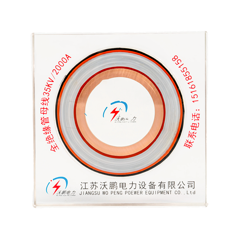
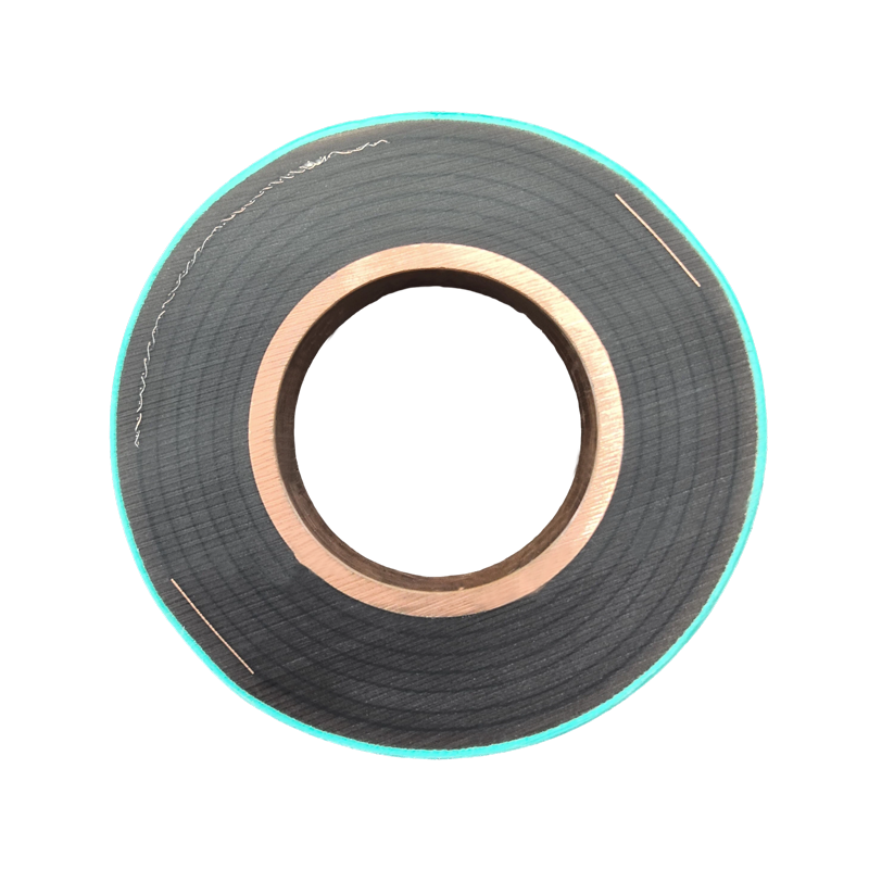
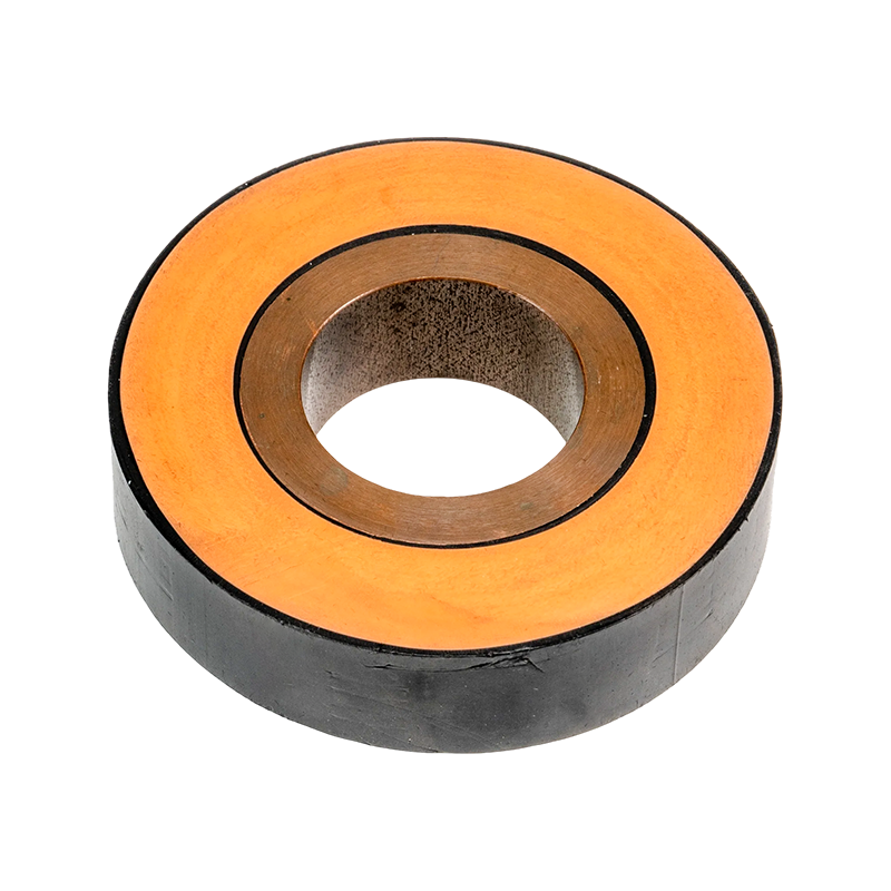
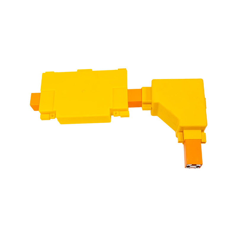

Ultra-High Voltage Magnesium-Aluminum Alloy Tubular Bus Bar: Performance, Manufacturing, and Applications
Content
- 1 1. Understanding the Ultra-High Voltage Magnesium-Aluminum Alloy Tubular Bus Bar
- 2 2. Why Tubular Geometry Is Important in Ultra-High Voltage Systems
- 3 3. Core Technical Advantages
- 4 4. Comparison with Traditional Busbar Solutions
- 5 5. Advanced Manufacturing Process
- 6 6. Quality Assurance and Testing
- 7 7. Application Areas
- 8 8. Engineering and Installation Considerations
- 9 9. Manufacturer Strengths and Customization Capability
- 10 10. How to Select a Suitable Product
- 11 11. Frequently Asked Questions
- 11.1 Q1: What is the main advantage of a magnesium-aluminum alloy tubular busbar?
- 11.2 Q2: Can this busbar be used in 500 kV and 1000 kV systems?
- 11.3 Q3: How does it compare with a copper busbar?
- 11.4 Q4: How does it compare with an ordinary aluminum busbar?
- 11.5 Q5: Is the tubular busbar suitable for outdoor installation?
- 11.6 Q6: What operating temperature can the product withstand?
- 11.7 Q7: Can the busbar be insulated?
- 11.8 Q8: What is the maximum support span?
- 11.9 Q9: What service life can be expected?
- 11.10 Q10: What information is needed for a quotation?
- 11.11 Q11: Does the manufacturer provide customized OEM solutions?
- 11.12 Q12: What quality documents should customers request?
- 12 12. Conclusion
- 13 References
- 14 Product: Ultra-high Voltage Magnesium-Aluminum Alloy Tubular Bus Bar
Ultra-high voltage power systems require conductive equipment that can carry substantial current, maintain electrical stability, withstand mechanical loads, and operate reliably in demanding outdoor environments. As transmission networks expand toward higher voltage levels and larger power capacities, the design of busbar systems becomes increasingly important. The conductor must not only provide low electrical resistance, but also control temperature rise, limit corona activity, resist corrosion, and maintain structural integrity over decades of service.
The ultra-high voltage magnesium-aluminum alloy tubular bus bar is developed to address these requirements. It combines the low density and good conductivity of aluminum with the increased strength and corrosion resistance associated with carefully engineered alloying elements. Its tubular geometry further improves mechanical stiffness, heat dissipation, electric field control, and suitability for long-span installation.
This product is intended for demanding applications including 220 kV, 500 kV, 750 kV, ±800 kV, and 1000 kV power transmission and transformation systems, subject to project-specific design and verification. It can be manufactured in a range of alloy grades, including 6063G aluminum-magnesium alloy, LF21Y aluminum-manganese alloy, 6R05 rare-earth aluminum alloy, and 2A14 heat-resistant aluminum alloy. These material options allow engineers to balance conductivity, strength, temperature capability, manufacturability, and environmental resistance according to the operating conditions of each project.
Jiangsu Wopeng Power Technology Co., Ltd. specializes in high- and low-voltage busbar systems and provides customized tubular busbar solutions for power generation, substations, renewable energy, industrial facilities, rail transit, and other high-current applications. Through controlled alloy processing, seamless tube manufacturing, thermomechanical treatment, precision drawing, vacuum casting, machining, assembly, and electrical testing, the company supports the production of reliable busbar systems for modern infrastructure.
1. Understanding the Ultra-High Voltage Magnesium-Aluminum Alloy Tubular Bus Bar
An ultra-high voltage magnesium-aluminum alloy tubular bus bar is a hollow conductive tube designed to transmit and distribute large electrical currents within high-voltage and ultra-high voltage facilities. Unlike a flat strip conductor, the tubular conductor has a circular or otherwise engineered hollow cross-section. This geometry provides a favorable combination of electrical, thermal, mechanical, and installation characteristics.
The conductor body is produced from an aluminum-based alloy containing magnesium or other alloying additions. Depending on the required performance, rare-earth elements, manganese, copper, silicon, and heat-resistant alloying systems may also be incorporated. The alloy is selected and processed to achieve the required conductivity, tensile strength, elongation, bending resistance, thermal stability, surface quality, and corrosion performance.
In an ultra-high voltage substation, tubular bus bars may connect transformers, circuit breakers, disconnectors, reactors, instrument transformers, and other primary equipment. In power plants, they may form part of the high-current connection between generators and step-up transformers. In renewable energy systems, tubular busbars can be used in collector systems, substations, and high-capacity power conversion applications.
The word “ultra-high voltage” describes the electrical application rather than a single universal product configuration. Actual voltage ratings, clearances, insulation coordination, phase spacing, support spacing, current capacity, and corona-control requirements depend on the system design. Therefore, a professional manufacturer must evaluate the conductor together with the complete busbar arrangement, supporting insulators, fittings, joints, grounding system, and environmental conditions.
1.1 Typical Material Options
6063G aluminum-magnesium alloy is suitable when a balanced combination of conductivity, formability, surface quality, and structural performance is required. Its processing characteristics make it appropriate for tubular sections that require controlled dimensional accuracy and reliable finishing.
LF21Y aluminum-manganese alloy offers useful corrosion resistance and mechanical stability. It can be considered for applications where outdoor exposure, industrial atmosphere, and fabrication reliability are important factors.
6R05 rare-earth aluminum alloy is developed for enhanced performance through refined alloy composition and microstructural control. Rare-earth additions can help improve material stability, grain structure, and resistance to performance degradation under demanding service conditions.
2A14 heat-resistant aluminum alloy is intended for applications where elevated operating temperature and mechanical stability are important. The appropriate grade must be selected according to allowable temperature rise, short-circuit duty, continuous current, thermal expansion, and supporting structure.
The final alloy selection should never be based on conductivity alone. A complete technical assessment should consider current-carrying capacity, mechanical span, wind and ice loading, short-circuit forces, temperature, corrosion exposure, joint design, manufacturing route, and compatibility with insulation or surface treatment.
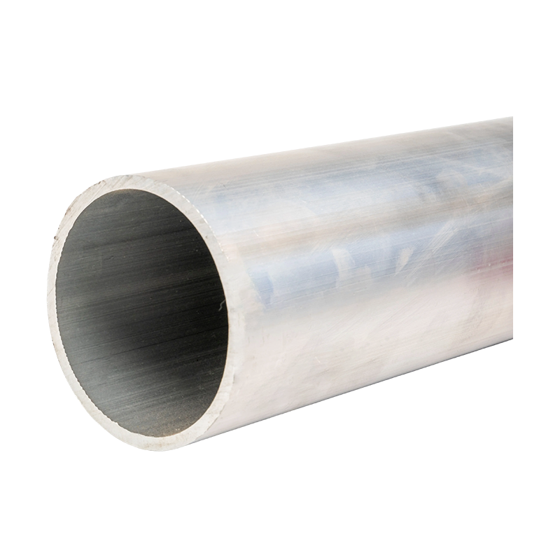
Ultra-high Voltage Magnesium-Aluminum Alloy Tubular Bus Bar
2. Why Tubular Geometry Is Important in Ultra-High Voltage Systems
The geometry of a busbar has a direct influence on electrical field distribution, mechanical behavior, thermal performance, and installation. Tubular bus bars are widely used in high-current applications because the hollow structure can provide high bending stiffness with lower material consumption than a solid conductor of comparable external diameter.
A tubular conductor distributes material around its outer circumference, increasing the section modulus and improving resistance to bending. This characteristic is valuable when the busbar must span between supports, withstand wind pressure, tolerate vibration, or resist electromagnetic forces during short-circuit events.
The circular outer surface also supports more uniform electric field distribution than many sharp-edged conductor shapes. With suitable diameter, spacing, surface quality, fittings, and grading components, the design can help reduce local electric field concentration and limit corona-related effects. In ultra-high voltage systems, this is especially important because corona can cause audible noise, radio interference, ozone formation, energy loss, and long-term surface deterioration.
The hollow interior reduces weight compared with a solid conductor of equivalent outside diameter. Lower weight can simplify lifting, support design, transportation, and installation. It may also reduce the mechanical load transferred to insulators and steel structures. This benefit becomes increasingly valuable when busbar spans are long or when multiple phases must be installed in large substations.
The outer surface of the tube is also favorable for convective heat dissipation. Heat generated by electrical resistance can transfer from the conductor surface to the surrounding air. In a properly designed system, this can help control temperature rise and support high continuous current ratings. Actual performance depends on conductor diameter, wall thickness, current distribution, ambient temperature, solar radiation, wind speed, phase arrangement, surface emissivity, and installation orientation.
2.1 Electrical Field Control
At ultra-high voltage, electric field control is a central design requirement. A busbar with a smooth, appropriately sized outer surface can reduce field concentration compared with a conductor containing abrupt corners, burrs, or irregular transitions. Manufacturing quality is therefore directly related to electrical reliability.
Seamless tube production is particularly beneficial because it eliminates weld seams that could create variations in surface geometry, local stress concentrations, or inconsistent electrical field conditions. Subsequent drawing and finishing operations can further improve dimensional accuracy and surface uniformity.
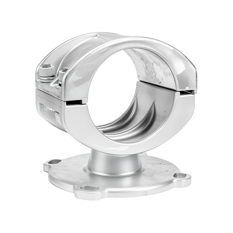
Busbar fittings must be designed with the same level of attention. Clamps, connectors, terminal plates, shielding rings, expansion joints, and other components should avoid sharp edges and unnecessary field concentration. A high-performance conductor cannot compensate for poorly designed fittings or insufficient phase clearance.
2.2 Mechanical Stiffness and Span Capability
Mechanical stiffness is one of the main advantages of a tubular busbar. The hollow section places material away from the neutral axis, increasing bending resistance without requiring the weight of a solid bar. Depending on conductor diameter, wall thickness, support structure, environmental loading, and allowable deflection, support spans may be extended compared with conventional arrangements.
The supplied product information indicates that support spans can reach up to approximately 8 meters in suitable designs. This figure should be treated as an engineering reference rather than a universal installation limit. The permitted span must be confirmed through structural calculations that include conductor weight, wind pressure, ice load, seismic acceleration, short-circuit forces, thermal expansion, fitting weight, and support deflection.
Longer spans may reduce the number of support insulators and structural members. This can simplify the layout, reduce installation points, improve visual organization, and potentially lower total system maintenance. However, span optimization must always be balanced against deflection, vibration, resonance, expansion movement, and the mechanical capacity of connected equipment.
3. Core Technical Advantages
The ultra-high voltage magnesium-aluminum alloy tubular bus bar offers a combined set of advantages that distinguishes it from traditional copper busbars, ordinary aluminum conductors, and certain welded tubular designs.
3.1 High Conductivity and Efficient Current Transmission
Aluminum-based conductors provide favorable electrical conductivity relative to their weight. By optimizing the alloy composition and processing route, the product can maintain strong current-carrying performance while achieving a lower mass than an equivalent copper solution.
The product information identifies electrical conductivity of at least 60% IACS for representative configurations. The exact value depends on alloy grade, temper, wall thickness, heat treatment, and production requirements. Conductivity should be verified using the applicable material standard and project test specification.
Low resistance helps reduce I²R losses during normal operation. Lower losses can improve the energy efficiency of substations and power plants, especially where large currents flow continuously. Reduced heat generation also supports more stable temperature control and may increase the available thermal margin of the system.
3.2 Lower Weight Than Copper Alternatives
Copper offers excellent conductivity and established mechanical performance, but it has a much higher density than aluminum alloys. A copper busbar system may therefore require heavier lifting equipment, stronger supports, larger handling teams, and more robust structural members.
A magnesium-aluminum alloy tubular busbar can reduce conductor mass while preserving a large external diameter and useful mechanical stiffness. The supplied comparison identifies a representative weight of approximately 8–12 kg per meter for the ultra-high voltage magnesium-aluminum alloy tubular busbar, compared with approximately 25–30 kg per meter for a traditional copper busbar. Actual values vary with diameter, wall thickness, alloy grade, and design current.
Weight reduction can influence the full project cost rather than only the conductor purchase price. It may reduce transportation requirements, simplify lifting, lower support loads, and enable more efficient structural design. For retrofit projects, reduced weight may also help when existing structures have limited reserve capacity.
3.3 Improved Strength-to-Weight Ratio
Magnesium-aluminum alloy systems can provide a useful balance between low density and structural strength. The product information describes tensile strength in the range of approximately 180–250 MPa for representative product configurations. The actual mechanical values must be confirmed according to alloy grade, temper, heat treatment, and applicable test standard.
A high strength-to-weight ratio is especially useful in outdoor substations, renewable energy installations, and rail transit environments. The busbar may be exposed to wind-induced vibration, thermal cycling, seismic motion, transport vibration, and short-circuit electromagnetic forces. A properly engineered alloy tube can resist deformation while limiting the weight transferred to its supports.
3.4 High-Temperature Capability
Electrical equipment can experience elevated temperatures during high-load operation, emergency overloads, or hot-weather conditions. Heat-resistant aluminum alloy options can maintain more stable mechanical and electrical performance at elevated temperature than standard grades intended for less demanding conditions.
The supplied technical information indicates operating temperatures up to approximately 150°C–200°C for suitable designs. The allowable value depends on the selected alloy, insulation system, surface treatment, joint design, support materials, continuous current, short-time current, and project standards.
High-temperature capability does not mean that a busbar should routinely operate at the maximum stated temperature. Continuous operation should be selected to meet the complete system’s thermal limits, including connected equipment, insulating materials, expansion devices, and support components. Proper thermal calculation and temperature-rise testing remain essential.
3.5 Corrosion and Weather Resistance
Outdoor ultra-high voltage equipment may be exposed to humidity, salt spray, industrial pollutants, dust, ultraviolet radiation, temperature changes, and condensation. An aluminum-based alloy naturally forms a protective oxide film, while suitable surface treatment can further improve corrosion resistance and insulation compatibility.
Special surface oxidation or other controlled treatment can help improve adhesion between the conductor surface and an insulation layer. This is important when the tubular conductor is used with epoxy vacuum casting, PTFE wrapping, or other insulation processes. Surface preparation must be controlled carefully because contamination, excessive roughness, or inconsistent treatment can affect bonding reliability.
For coastal and offshore wind installations, salt fog resistance is a major consideration. Material selection should be combined with appropriate sealing, drainage, joint protection, coating, inspection, and maintenance procedures. No conductor material eliminates the need for proper environmental design.
3.6 Resistance to Ice, Wind, and Vibration
Outdoor busbar systems must remain stable under changing weather. Ice accumulation can increase weight and alter the aerodynamic profile of the conductor. Wind can produce static pressure, vortex shedding, and vibration. Temperature changes can create expansion and contraction that place stress on joints and supports.
The tubular busbar is designed to support reliable operation under these conditions when installed with suitable fittings and structures. Its mechanical strength, circular profile, and resistance to vibration can help maintain alignment and reduce the risk of excessive deformation.
For seismic applications, the complete installation must be evaluated as a system. Conductor flexibility, support movement, insulator strength, equipment connection points, and seismic displacement requirements should be included in the design. A mechanically strong conductor is one part of a wider seismic solution.
4. Comparison with Traditional Busbar Solutions
Different busbar materials and geometries are appropriate for different voltage levels and current requirements. The following comparison illustrates typical positioning rather than a universal performance guarantee. Actual values depend on conductor dimensions, installation conditions, standards, and test methods.
| Busbar Type | Representative Weight | Typical Electrical Performance | Representative Maximum Voltage Application | Primary Considerations |
|---|---|---|---|---|
| Magnesium-aluminum alloy tubular busbar | Approximately 8–12 kg/m | Low loss with high current capability | Up to 1000 kV in suitable system designs | Low weight, high stiffness, controlled electric field, outdoor suitability |
| Traditional copper busbar | Approximately 25–30 kg/m | Very high conductivity | Commonly used across many high-voltage applications | High density, higher structural load, excellent conductivity |
| Ordinary aluminum busbar | Approximately 7–10 kg/m | Moderate to high conductivity depending on grade | Often applied in lower and medium voltage arrangements | Low weight, but application limits may arise from strength or thermal requirements |
Compared with copper, the magnesium-aluminum alloy tubular busbar can reduce mass and support a larger conductor diameter without imposing the same structural burden. A larger external diameter can be beneficial for electric field control, current capacity, and corona performance.
Compared with ordinary aluminum busbars, the optimized alloy and tubular structure can provide improved mechanical strength, better long-span capability, enhanced temperature resistance, and more controlled dimensional performance. The difference is not simply the base metal; it also results from alloy formulation, casting, hot rolling, drawing, heat treatment, finishing, and quality control.
Compared with welded tubes, a seamless product eliminates the potential weakness associated with a continuous weld seam. Seamless production can provide more uniform mechanical behavior and surface continuity, which are valuable in ultra-high voltage applications where local irregularities can influence electric field performance.
Compared with flat busbars, the tubular design generally offers improved bending stiffness and more favorable field distribution. However, flat bars may remain suitable for compact low-voltage systems or applications where space, connection style, and cost have different priorities. Product selection should be based on system requirements rather than a single performance characteristic.
5. Advanced Manufacturing Process
The performance of a tubular busbar depends heavily on how the alloy is melted, cast, formed, treated, drawn, finished, and tested. Advanced manufacturing processes help convert the theoretical advantages of an alloy into stable production quality.
5.1 Alloy Formulation and Material Control
The manufacturing process begins with controlled raw materials and an alloy formulation selected for the intended application. The composition must be managed within defined limits so that conductivity, strength, heat resistance, corrosion resistance, and formability remain consistent from batch to batch.
Material control includes raw material identification, weighing, melting temperature management, impurity control, sampling, chemical analysis, and batch traceability. For high-voltage products, consistency is particularly important because variations in composition can influence electrical resistance, mechanical strength, thermal expansion, surface quality, and response to subsequent processing.
Rare-earth and heat-resistant alloy formulations can be used where additional mechanical or thermal performance is needed. The formulation should be selected with consideration for the manufacturing route. An alloy that performs well in service must also be suitable for casting, piercing, rolling, drawing, machining, and joining.
5.2 Horizontal Hot-Top Casting
Horizontal hot-top casting technology is used to improve control over solidification and material quality. The process is intended to support high material purity, stable billet formation, and a more uniform microstructure.
Careful control of melt temperature, casting speed, cooling conditions, and metal flow can help reduce internal defects, segregation, porosity, and irregular grain structures. A uniform starting billet provides a more reliable basis for subsequent hot working and tube formation.
For ultra-high voltage conductors, internal quality matters even when defects cannot be seen on the finished surface. Internal discontinuities can reduce mechanical reliability, affect forming behavior, and create local differences in electrical or thermal performance. For this reason, material inspection and process records are essential parts of production control.
5.3 Transverse Piercing and Hot Rolling
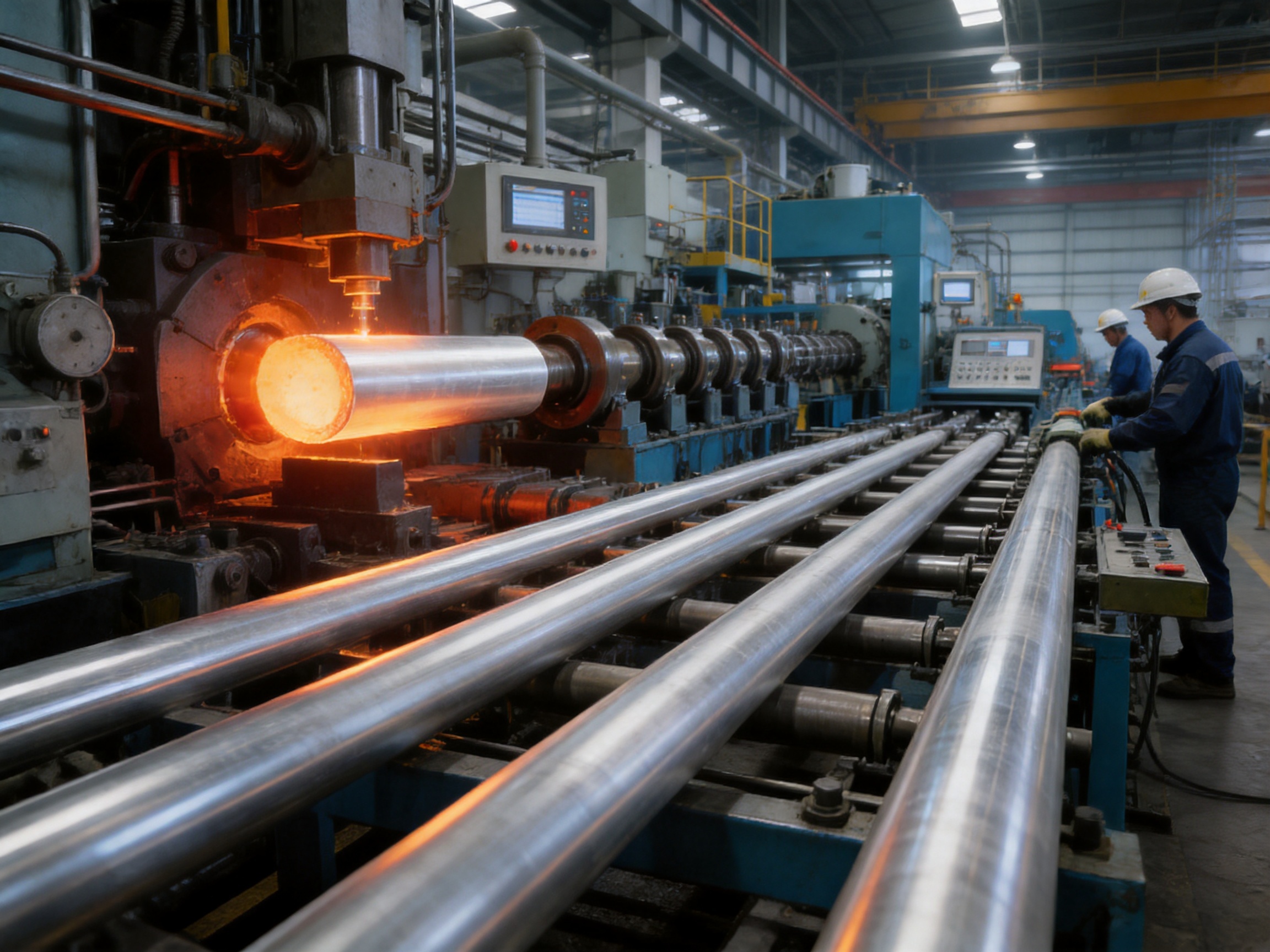
Transverse piercing hot rolling is used to produce a hollow tube from a solid billet. The process forms the internal opening and progressively develops the outer and inner dimensions of the tube.
This approach supports seamless tube production and avoids the weld seam associated with welded tubular conductors. By eliminating a longitudinal weld, the product can achieve more uniform mechanical behavior around the circumference. It also reduces the risk that a weld-related surface irregularity will affect electric field distribution.
During hot rolling, key process parameters include billet temperature, piercing force, rolling speed, reduction ratio, mandrel conditions, cooling, and dimensional control. These parameters influence wall thickness, concentricity, surface quality, grain flow, and residual stress.
Consistent wall thickness is important for both mechanical and electrical reasons. Excessive variation can lead to uneven stiffness, inconsistent weight, dimensional difficulty during assembly, and localized thermal behavior. Precision process control helps ensure that the finished tube meets its specified tolerances.
5.4 Thermomechanical Treatment
Thermomechanical treatment combines controlled deformation and heat treatment to refine the material structure and obtain a suitable balance of strength, conductivity, ductility, and stability. The treatment schedule may include solution treatment, aging, stress relief, controlled cooling, or other steps appropriate to the selected alloy.
The objective is not simply to maximize strength. Excessive strengthening can reduce formability or conductivity, while insufficient treatment may result in inadequate mechanical stability. A carefully designed process produces a conductor that can be handled, installed, and operated without losing its intended performance.
Thermal treatment also helps manage residual stress introduced during casting, piercing, rolling, and drawing. Lower residual stress can improve dimensional stability and reduce the likelihood of distortion during cutting, machining, surface treatment, or assembly.
5.5 Multipass Cold Drawing
Multipass cold drawing is used to achieve precise dimensions, improve surface quality, and control the final tube profile. The tube passes through a series of dies, with reductions distributed over multiple stages rather than imposed in a single operation.
Multipass processing allows closer control of outside diameter, inside diameter, wall thickness, concentricity, and straightness. It can also produce a smoother surface that is beneficial for high-voltage electric field control and for subsequent insulation or coating operations.
Drawing schedules must be selected according to alloy behavior, reduction ratio, lubrication, intermediate annealing, die condition, and final temper requirements. Excessive deformation without suitable intermediate treatment can cause cracking, excessive residual stress, or unacceptable loss of ductility.
5.6 Surface Treatment and Insulation Compatibility
The finished conductor may undergo cleaning, oxidation, passivation, coating, polishing, or other surface treatment depending on the application. The objective may include improved corrosion resistance, enhanced insulation adhesion, better surface uniformity, and protection during storage and installation.
For epoxy vacuum-cast systems, surface cleanliness and controlled surface energy are important for adhesion. For PTFE wrapping or other insulation systems, dimensional accuracy and surface smoothness help prevent air gaps, wrinkles, and local stress concentrations.
Surface treatment must be compatible with joints and electrical connections. Contact areas may require specific preparation to maintain low contact resistance. Protective treatments should not interfere with reliable bolted, welded, brazed, or mechanically compressed connections unless the joint design specifically accounts for them.
5.7 Precision Machining and Assembly
After tube production, the conductor may be cut to length, machined at the ends, drilled, grooved, formed, or fitted with connection components. CNC machining helps maintain repeatable dimensions and supports the production of customized terminal interfaces.
Assembly may include clamps, expansion joints, shielding components, flexible connectors, end fittings, insulation elements, support interfaces, and grounding provisions. Each component must be aligned with the conductor and designed to avoid unnecessary electric field concentration.
Modern production lines equipped with vacuum casting systems, CNC equipment, and automated assembly technologies help improve repeatability and reduce manual variation. Automation is particularly valuable for recurring operations such as dimensional positioning, component fastening, and process recording.
6. Quality Assurance and Testing
A reliable ultra-high voltage busbar manufacturer must provide more than a material certificate. The product should be supported by a quality system that covers raw materials, manufacturing processes, dimensional inspection, electrical testing, mechanical verification, assembly control, and final documentation.
6.1 Material and Dimensional Inspection
Material inspection may include chemical composition analysis, conductivity testing, tensile testing, elongation measurement, hardness verification, and metallographic evaluation. The selected tests depend on the alloy grade, customer specification, and applicable standard.
Dimensional inspection normally includes outside diameter, inside diameter, wall thickness, straightness, length, end preparation, concentricity, surface roughness, and fitting position. These measurements help ensure that the conductor can be assembled correctly and that the designed electrical and mechanical clearances are maintained.
6.2 Electrical Tests
Electrical tests may include resistance measurement, insulation resistance testing, power-frequency withstand testing, partial discharge testing, corona assessment, and temperature-rise testing. The exact test program depends on whether the product is supplied as a bare conductor, insulated tubular busbar, complete busway, or integrated high-voltage assembly.
For an ultra-high voltage system, the complete arrangement should be evaluated rather than relying only on a sample tube test. Fittings, supports, joints, insulation interfaces, and field-control components can all influence electrical performance.
6.3 Mechanical Verification
Mechanical verification may include tensile tests, bending tests, vibration evaluation, support-span calculations, thermal expansion analysis, and short-circuit force assessment. When required, the complete busbar assembly can be checked under simulated environmental or seismic conditions.
Short-circuit forces can be significant because the current in parallel conductors produces electromagnetic interaction. The support system, clamps, joints, and insulators must be designed to maintain stability during fault events. The conductor’s strength is important, but so are connection integrity and structural restraint.
6.4 Third-Party and Type Testing
Testing collaboration with independent institutions can provide additional validation of product safety and performance. Type test reports are particularly valuable for large projects, utility procurement, and applications where the busbar must satisfy defined high-voltage standards.
Customers should request relevant test documentation, inspection records, material certificates, quality plans, and project references. A manufacturer with experience in multiple provinces, industrial sectors, and high-current applications is better positioned to understand the practical requirements of installation and long-term service.
7. Application Areas
7.1 Ultra-High Voltage Substations
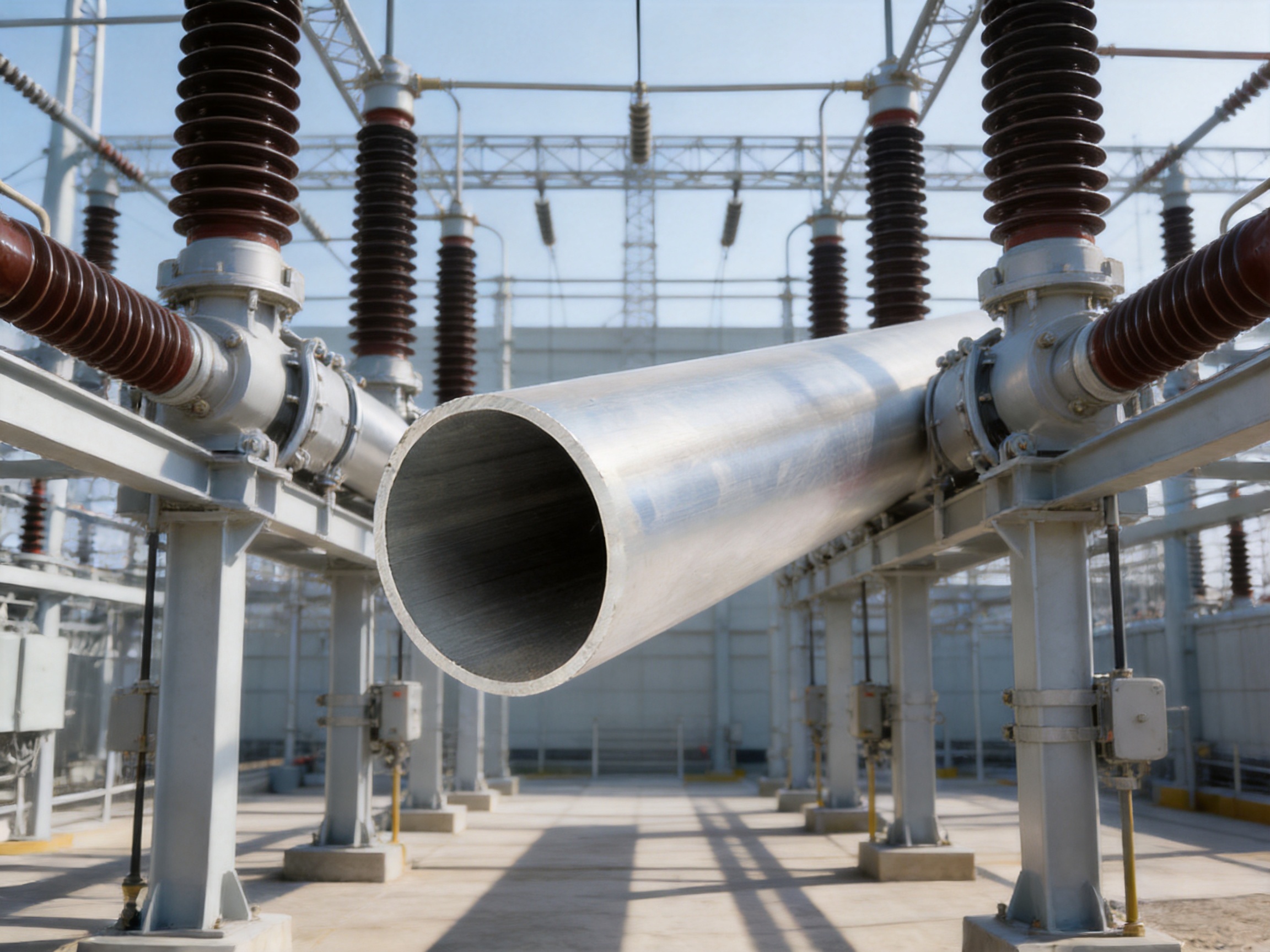
In substations rated at 500 kV and above, tubular busbars can connect transformers, circuit breakers, disconnectors, voltage transformers, current transformers, reactors, and other primary equipment. Their large diameter and smooth surface can support electric field control, while their stiffness can help maintain phase alignment over extended spans.
Substation layouts often include complex equipment arrangements and strict clearance requirements. A customized tubular busbar can be designed with specific lengths, bends, terminals, support interfaces, and expansion provisions to match the site layout.
7.2 Power Generation Plants
Hydropower, thermal power, nuclear-related auxiliary systems, and large renewable generation plants require high-capacity connections between generators, transformers, switchgear, and grid interfaces. A lightweight tubular conductor can reduce the structural load of high-current connections while maintaining suitable electrical performance.
Generation plants may also face vibration, temperature variation, moisture, dust, and restricted installation access. The conductor and fittings should therefore be designed for maintenance accessibility, thermal expansion, and reliable connection to plant equipment.
7.3 Wind Power and Photovoltaic Systems
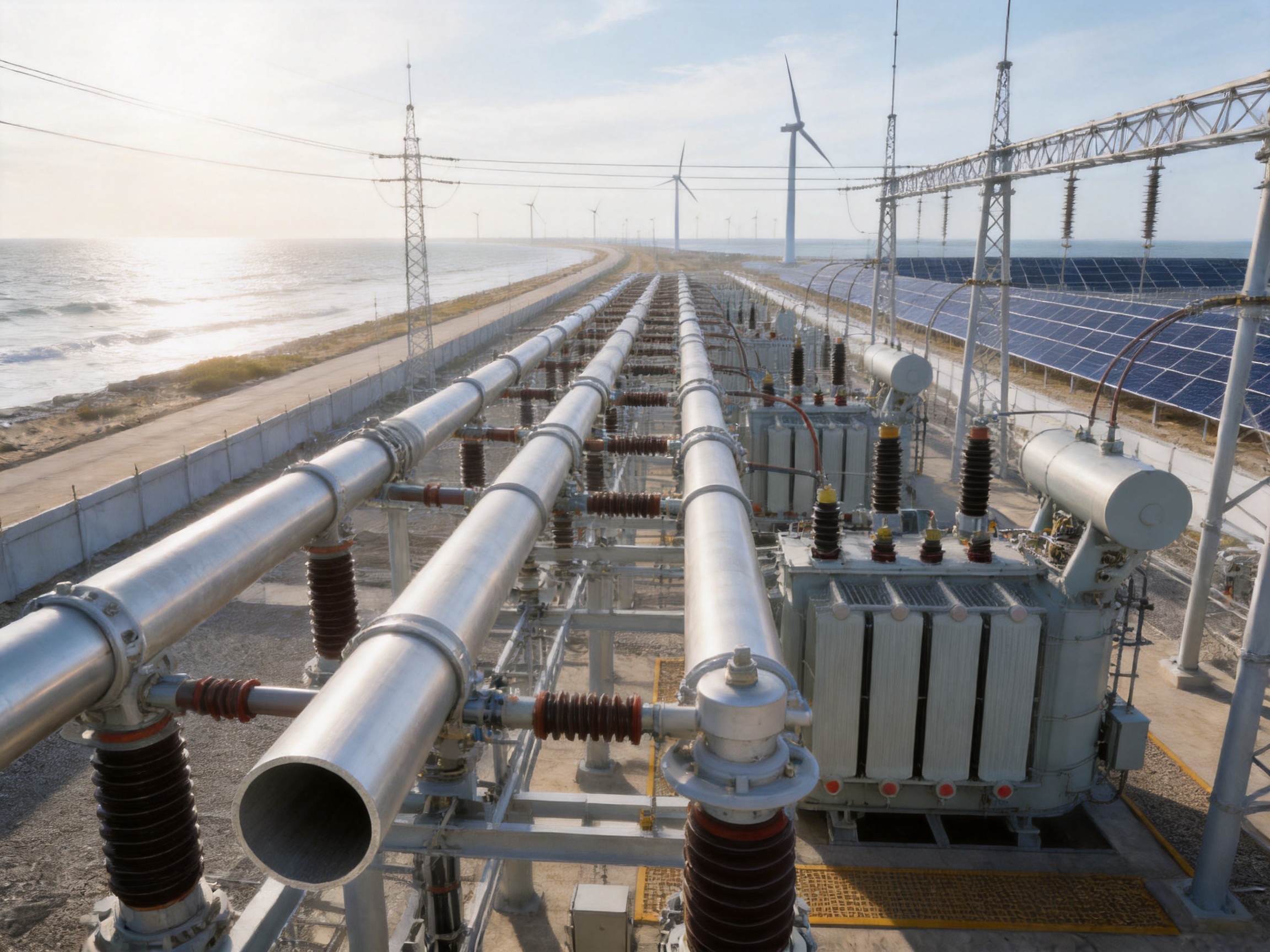
Large wind farms and photovoltaic power stations increasingly require high-capacity collector networks and substations. Wind power installations may experience strong vibration, salt fog, high wind pressure, and limited access for maintenance. Magnesium-aluminum alloy tubular busbars can support lightweight design and corrosion-conscious engineering.
In photovoltaic facilities, high solar exposure can raise ambient conductor temperature. Thermal calculations should consider solar radiation, air circulation, enclosure effects, and continuous current. Tubular geometry and suitable surface treatment can help manage the thermal and environmental demands of outdoor installations.
7.4 Offshore and Coastal Power Systems
Offshore wind farms, coastal substations, and marine industrial facilities are exposed to salt spray and high humidity. These conditions increase the risk of corrosion at conductor surfaces, joints, fasteners, and support components.
For these projects, the busbar system should incorporate suitable alloy selection, surface protection, sealing, drainage, corrosion-resistant hardware, and inspection procedures. The conductor must be evaluated together with the complete environmental protection strategy.
7.5 Industrial Distribution
Metallurgical plants, chemical facilities, mining operations, data centers, and large manufacturing plants often require high-current distribution with a compact and reliable arrangement. Tubular busbars can provide a structured solution where current levels, available space, mechanical loading, and safety requirements exceed the capability of ordinary flat busbars.
Industrial applications may involve corrosive atmospheres, dust, elevated temperatures, vibration, or frequent load changes. The alloy, insulation, enclosure, support spacing, and maintenance plan should be matched to the site conditions.
7.6 Rail Transit and Specialized Infrastructure
Rail transit systems require dependable power distribution under vibration, movement, and restricted spatial conditions. The high strength-to-weight ratio of a magnesium-aluminum alloy tube can support lightweight system design, while its dimensional precision can simplify integration with insulation and support assemblies.
Specialized facilities, including aerospace-related infrastructure and high-altitude power stations, may also benefit from reduced weight, corrosion resistance, and stable performance over a wide temperature range. Each application requires validation against its own safety and environmental standards.
8. Engineering and Installation Considerations
Correct product selection is only the first step in achieving reliable performance. The busbar system must be engineered around current, voltage, short-circuit duty, environmental exposure, support configuration, insulation, and maintenance requirements.
8.1 Current and Thermal Design
Continuous current should be calculated based on conductor dimensions, alloy conductivity, ambient temperature, airflow, solar radiation, surface condition, phase arrangement, and allowable temperature rise. Emergency and short-time current conditions should also be considered.
Connections often generate more heat than the conductor body if contact pressure, surface preparation, or joint design is inadequate. Joint resistance should be controlled through suitable materials, contact geometry, tightening procedures, and inspection.
8.2 Electrical Clearances and Insulation Coordination
Ultra-high voltage installations require carefully calculated phase-to-phase and phase-to-ground clearances. The conductor diameter, support height, surrounding structures, atmospheric conditions, switching overvoltage, lightning impulse, and pollution level all influence insulation coordination.
Where insulated tubular busbars are used, the insulation system should be evaluated for dielectric strength, partial discharge, thermal aging, moisture resistance, mechanical adhesion, and compatibility with the conductor surface treatment.
8.3 Thermal Expansion
Aluminum alloys expand as temperature rises. Long busbar runs should therefore include expansion provisions or flexible connections where necessary. Expansion joints must carry the required current without creating excessive contact resistance, while also accommodating movement without imposing large forces on connected equipment.
8.4 Support and Seismic Design
Support spacing should be determined through mechanical calculation rather than by relying on a nominal span value. The design should account for conductor weight, wind, ice, seismic acceleration, short-circuit forces, thermal movement, and fitting mass.
Supports should maintain alignment while allowing the movement required by thermal expansion and seismic displacement. Rigidly restraining a long conductor at too many points can create excessive thermal stress.
8.5 Transportation and Site Handling
Although the alloy tubular busbar is lighter than a comparable copper solution, it still requires careful handling. Tubes should be protected from impact, contamination, bending, and surface damage during storage and transport.
End fittings and machined surfaces should be protected until assembly. Lifting points must be selected to prevent local deformation. Before installation, the conductor should be inspected for dents, scratches, contamination, dimensional damage, and evidence of moisture ingress.
9. Manufacturer Strengths and Customization Capability
Jiangsu Wopeng Power Technology Co., Ltd. was established in 2018 as a specialized high- and low-voltage busbar system manufacturer. The company focuses on the development and production of power transmission products for high-current and critical operating conditions.
Its product portfolio includes 35 kV epoxy resin vacuum-cast tubular busbars, low-voltage cast-resin busways, copper and aluminum tubular busbars, wind power tubular busbars, compact busbar systems, and sliding contact line systems. This product range gives the engineering team experience across different voltage levels, insulation technologies, conductor materials, and installation environments.
The company serves power generation, substations, wind energy, industrial manufacturing, rail transit, commercial facilities, and other infrastructure sectors. Its products operate across more than 17 provinces and industrial regions, providing practical exposure to different climates, site conditions, project requirements, and customer specifications.
Its production capabilities include vacuum casting, CNC machining, controlled tube processing, automated assembly, and standardized inspection. These capabilities support both standard products and customized OEM solutions. Customers may require special conductor diameters, wall thicknesses, connection arrangements, insulation systems, support spacing, terminal geometry, or environmental protection. A manufacturer with integrated engineering and production resources can address these requirements more efficiently than a supplier limited to a single standard configuration.
The company’s engineers, technical specialists, and production professionals provide support from initial design review through manufacturing, testing, delivery, and technical documentation. This integrated approach helps ensure that the conductor, insulation, fittings, and installation interfaces function as a complete system.
Quality management includes high-voltage tests, insulation tests, mechanical verification, routine inspection, and cooperation with third-party testing institutions. These measures help reinforce product reliability and give customers a clearer basis for technical approval and procurement decisions.
10. How to Select a Suitable Product
When selecting an ultra-high voltage magnesium-aluminum alloy tubular busbar, customers should provide the manufacturer with complete project information. The required voltage level, rated current, short-circuit current, ambient temperature, altitude, pollution level, wind speed, ice load, seismic intensity, installation span, and insulation arrangement all affect the final design.
The requested technical documentation should include material grade, conductivity, tensile strength, allowable operating temperature, dimensional tolerances, surface treatment, joint resistance, insulation performance, type test information, and installation recommendations.
Customers should also clarify whether they need a bare tubular conductor, an insulated tubular busbar, a complete busbar assembly, a prefabricated connection system, or a customized OEM product. These configurations have different design, testing, packaging, and installation requirements.
Supplier evaluation should include manufacturing capability, process traceability, quality system, engineering experience, production capacity, delivery record, after-sales support, and project references. A competitive price is useful, but it should not replace verification of long-term electrical and mechanical reliability.
11. Frequently Asked Questions
Q1: What is the main advantage of a magnesium-aluminum alloy tubular busbar?
The main advantage is the combination of low weight, good conductivity, high mechanical stiffness, corrosion resistance, and suitability for large-current transmission. The tubular structure provides strong bending resistance and favorable electric field characteristics, while the aluminum-based alloy reduces mass compared with copper.
Q2: Can this busbar be used in 500 kV and 1000 kV systems?
It can be designed for ultra-high voltage systems including 500 kV, 750 kV, ±800 kV, and 1000 kV applications, provided that the complete conductor, fitting, support, insulation, clearance, and testing requirements are satisfied. The applicable voltage level must be confirmed through project-specific engineering and type testing.
Q3: How does it compare with a copper busbar?
The magnesium-aluminum alloy tubular busbar is significantly lighter than a comparable copper solution and can provide a favorable strength-to-weight ratio. Copper may provide higher conductivity per unit area, but its greater density increases structural loads and handling requirements. The final choice should consider total system performance, not only material conductivity.
Q4: How does it compare with an ordinary aluminum busbar?
The optimized alloy composition, seamless tubular construction, thermomechanical treatment, and precision drawing can provide improved mechanical strength, temperature capability, surface quality, and long-span performance compared with ordinary aluminum busbars. The appropriate comparison depends on the specific dimensions and alloy grades being evaluated.
Q5: Is the tubular busbar suitable for outdoor installation?
Yes. With suitable alloy selection, surface treatment, fittings, sealing, and maintenance, it can be used in outdoor substations, wind farms, photovoltaic facilities, coastal systems, and other exposed environments. Salt spray, humidity, pollution, wind, ice, and temperature conditions should be included in the design review.
Q6: What operating temperature can the product withstand?
Suitable heat-resistant alloy configurations can support operating temperatures in the approximate range of 150°C–200°C. The actual continuous and short-time temperature limits depend on alloy grade, conductor dimensions, insulation, fittings, support materials, current, ambient conditions, and the applicable standard.
Q7: Can the busbar be insulated?
Yes. The conductor can be compatible with insulation processes such as epoxy vacuum casting and PTFE wrapping when the surface preparation, dimensional tolerances, curing process, and insulation design are properly controlled. The insulation system should be verified for adhesion, dielectric strength, partial discharge, thermal aging, and environmental resistance.
Q8: What is the maximum support span?
A support span of up to approximately 8 meters may be achievable in suitable designs. The actual maximum span must be determined by structural calculations that consider conductor dimensions, wind, ice, seismic forces, short-circuit forces, thermal expansion, support strength, and allowable deflection.
Q9: What service life can be expected?
With appropriate material selection, anti-corrosion treatment, installation, inspection, and maintenance, the product can be designed for a service life of approximately 30–40 years under normal operating conditions. Actual service life depends on voltage stress, current, environmental exposure, mechanical loading, joint condition, and maintenance quality.
Q10: What information is needed for a quotation?
Important information includes system voltage, rated current, short-circuit level, conductor length, outside diameter, wall thickness, support span, insulation type, terminal arrangement, environmental conditions, quantity, required tests, delivery location, and applicable standards. Drawings, single-line diagrams, equipment interface details, and installation conditions are also helpful.
Q11: Does the manufacturer provide customized OEM solutions?
Yes. Customized solutions can include alloy selection, tube dimensions, conductor length, end machining, connection fittings, insulation, surface treatment, support interfaces, packaging, testing, and documentation. The final design is developed according to the customer’s technical specification and project conditions.
Q12: What quality documents should customers request?
Customers should request material certificates, chemical composition reports, conductivity results, mechanical test reports, dimensional inspection records, high-voltage and insulation test reports, type test documentation where applicable, quality plans, installation instructions, and traceability records. The documentation package should match the project’s procurement and acceptance requirements.
12. Conclusion
The ultra-high voltage magnesium-aluminum alloy tubular bus bar is a high-performance solution for power systems that require efficient current transmission, mechanical stability, controlled electric fields, and reduced structural weight. Its value results from the combination of alloy engineering, tubular geometry, seamless production, thermomechanical treatment, precision drawing, surface treatment, and complete system testing.
Compared with traditional copper busbars, it can reduce weight and structural loading while retaining strong electrical and mechanical performance. Compared with ordinary aluminum busbars, it can offer improved strength, temperature resistance, corrosion performance, dimensional control, and suitability for demanding long-span installations. Compared with welded tubular designs, seamless production can provide more uniform mechanical and surface characteristics.
The product is suitable for ultra-high voltage substations, power plants, renewable energy installations, offshore and coastal projects, industrial power distribution, rail transit, and specialized infrastructure. Its performance is strongest when the conductor is engineered as part of a complete system that includes fittings, supports, insulation, expansion provisions, grounding, testing, and maintenance.
Jiangsu Wopeng Power Technology Co., Ltd. combines high- and low-voltage busbar expertise with modern manufacturing equipment, controlled production processes, customized engineering, and standardized testing. Its experience in tubular busbars, cast-resin systems, wind power applications, compact busways, and sliding contact lines supports the development of practical power transmission solutions for different industries and environmental conditions.
For project owners, electrical contractors, design institutes, and equipment integrators, the best procurement decision should be based on verified technical data, complete application analysis, reliable manufacturing control, and long-term service support. When these factors are addressed together, the ultra-high voltage magnesium-aluminum alloy tubular bus bar can contribute to safer, lighter, more efficient, and more maintainable power transmission systems.
References
1. International Electrotechnical Commission. High-Voltage Alternating-Current Switchgear and Controlgear Standards.
2. International Electrotechnical Commission. Power Installations Exceeding 1 kV AC and Related Insulation Coordination Guidance.
3. International Electrotechnical Commission. Electrical Conductivity and Mechanical Testing Methods for Aluminum and Aluminum Alloys.
4. American Society for Testing and Materials. Standard Test Methods for Aluminum and Aluminum-Alloy Products.
5. Aluminum Association. Aluminum Standards and Data for Electrical and Structural Applications.
6. IEEE. Guide for Design, Testing, and Application of High-Voltage Busbar Systems.
7. Technical data and manufacturing information supplied for the ultra-high voltage magnesium-aluminum alloy tubular busbar product.
8. Technical information supplied by Jiangsu Wopeng Power Technology Co., Ltd. concerning busbar manufacturing, testing, product applications, and company capabilities.
Product: Ultra-high Voltage Magnesium-Aluminum Alloy Tubular Bus Bar




-
 +86-180 3625 3000
-
 admin@wpbusbar.com
-
 No. 8, Yanjin Road, Chengxi Industrial Park, Shanyang Town, Baoying County, Yangzhou City, Jiangsu Province, China
Copyright © Jiangsu Wopeng Power Technology Co., Ltd.
All Rights Reserved.
 Custom Insulated Bus Bar Manufacturer
Tubular Busbar System Factory