

 EN

 English
 русский
 Français
 Español
 عربى

High-Voltage EPDM Silicone Rubber Tubular Bus Bar: Structure, Advantages, Applications, and Manufacturing Quality
Content
- 1 1. Overview of the EPDM Silicone Rubber Tubular Bus Bar
- 2 2. Composite Shielded Insulation Design
- 3 3. Electrical and Mechanical Performance
- 4 4. Prefabricated Cold-Shrink Terminations and Joints
- 5 5. Advantages Compared with Conventional Insulated Busbars
- 6 6. Environmental and Operational Advantages
- 7 7. Typical Application Solutions
- 8 8. Manufacturing Process and Quality Control
- 9 9. Manufacturer Strengths and Customization Capability
- 10 10. Selection Guidelines for Project Engineers
- 11 11. Installation and Maintenance Considerations
- 12 12. Frequently Asked Questions
- 12.1 Q1: What is an EPDM silicone rubber tubular bus bar?
- 12.2 Q2: What voltage range is this product suitable for?
- 12.3 Q3: Is the busbar available with copper and aluminum conductors?
- 12.4 Q4: What is the purpose of triple-layer co-extrusion?
- 12.5 Q5: How does the product control the electric field?
- 12.6 Q6: Can it be installed outdoors?
- 12.7 Q7: Can it operate in a wet or temporarily submerged location?
- 12.8 Q8: What current can the tubular busbar carry?
- 12.9 Q9: Why are stress cones used in the terminations?
- 12.10 Q10: What information should be provided when requesting a quotation?
- 12.11 Q11: What testing should be requested from the supplier?
- 12.12 Q12: Why choose an experienced tubular busbar manufacturer?
- 13 13. Conclusion
- 14 References
- 15 Product: EPDM Silicone Rubber Tubular Bus Bar
Modern power distribution systems require conductors that can transport substantial electrical current while maintaining dependable insulation, mechanical strength, environmental resistance, and installation flexibility. Traditional bare busbars may require large clearances and additional insulation barriers, while some conventional insulated conductors can be difficult to install in high-current applications. The EPDM silicone rubber tubular bus bar provides an engineered alternative by combining a tubular copper or aluminum conductor with a composite shielded insulation system.
This type of tubular bus bar is designed for medium- and high-voltage power transmission, particularly in substations, transformer connections, switchgear systems, industrial facilities, renewable energy installations, and other power infrastructure projects. Its construction integrates the conductor, conductor shielding, insulation, insulation shielding, metallic shielding, and outer sheath into a coordinated system. The result is a compact, fully insulated busbar solution that supports safe operation in demanding indoor and outdoor environments.
Jiangsu Wopeng Power Technology Co., Ltd. develops and manufactures high- and low-voltage busbar systems, including insulated tubular busbars, copper and aluminum tubular busbars, epoxy resin cast tube busbars, compact busbar systems, and sliding contact line systems. Through polymer processing, vacuum casting, CNC machining, automated assembly, and standardized inspection procedures, the company provides customized solutions for high-current and critical power applications.
1. Overview of the EPDM Silicone Rubber Tubular Bus Bar
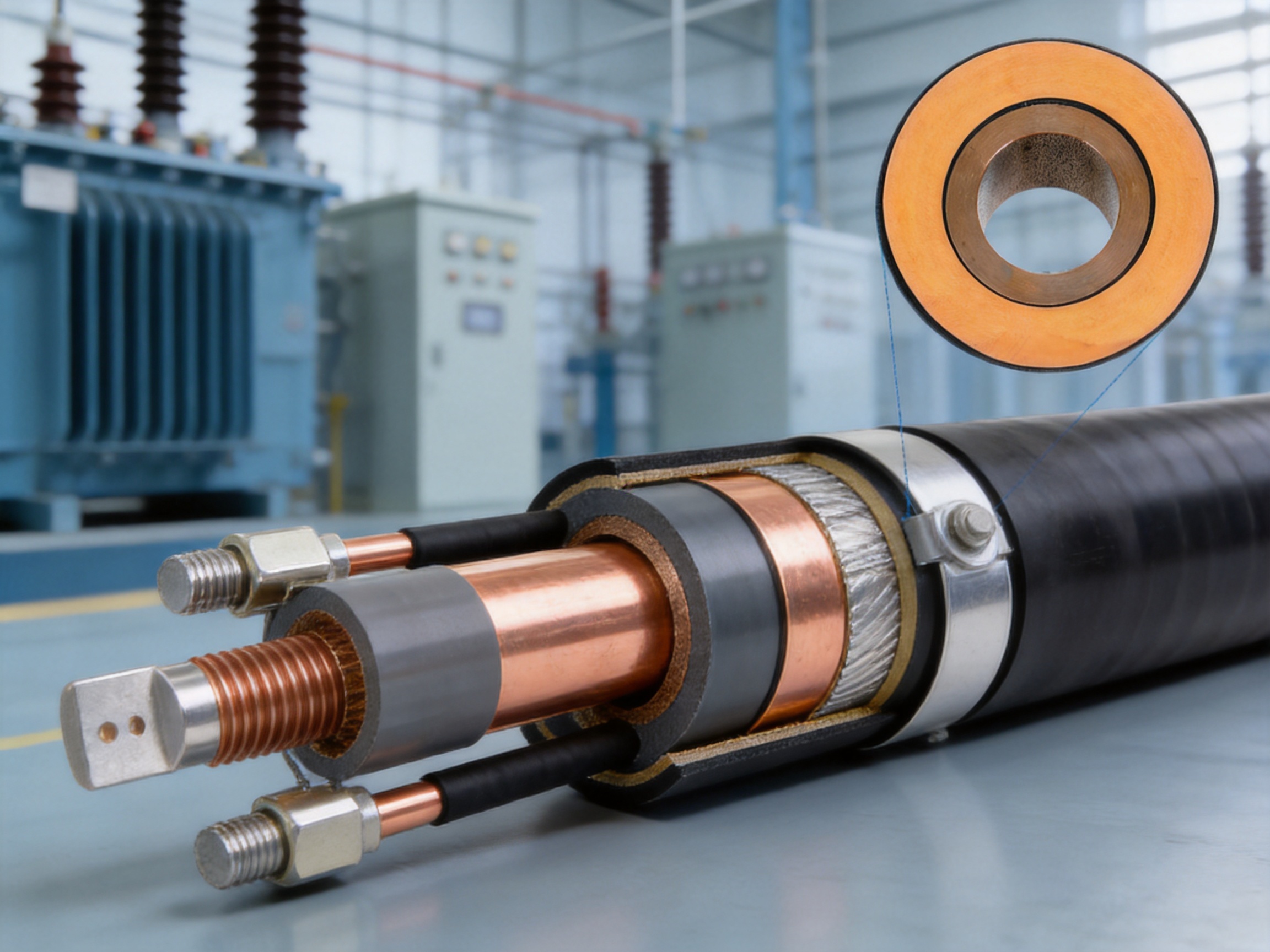
The EPDM silicone rubber tubular bus bar is a composite insulated conductor designed to transmit electrical power while controlling the electric field around the conductor. Its primary conductor is normally manufactured from a solid copper tube or an aluminum alloy tube, depending on the required current rating, weight, installation conditions, and project budget.
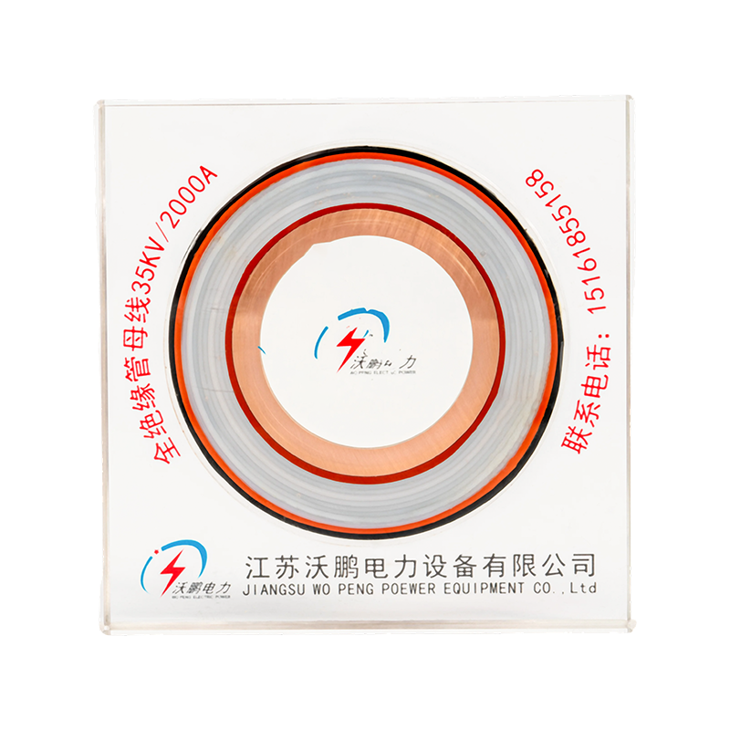
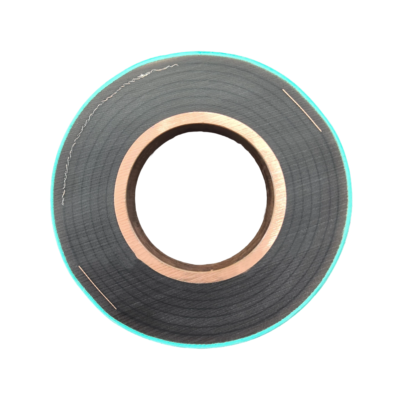
Unlike a simple conductor covered with a single layer of insulation, this product uses a composite shielded structure. The conductor is surrounded by a conductor shielding layer, a primary EPDM-based insulation layer, an insulation shielding layer, a metallic shielding layer, and an external protective sheath. These layers work together to improve electrical performance, reduce localized electric-field concentration, and provide mechanical and environmental protection.
The product is manufactured using triple-layer co-extrusion technology. During this process, the conductor shielding, primary insulation, and insulation shielding are formed in a controlled and coordinated extrusion operation. The simultaneous formation of these layers helps create tight interfaces without significant air gaps between the components. This is important because air pockets, uneven insulation thickness, or weak interfaces can create local electrical stress and increase the risk of partial discharge.
The completed tubular busbar is intended to function as a fully insulated power transmission path. Its shielded joints and prefabricated terminal components allow the insulation system to continue through connection points, helping maintain a consistent level of protection along the complete installation.
1.1 Main Structural Components
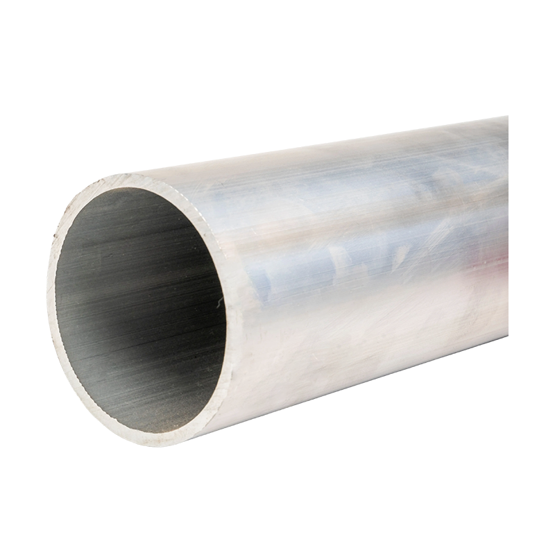
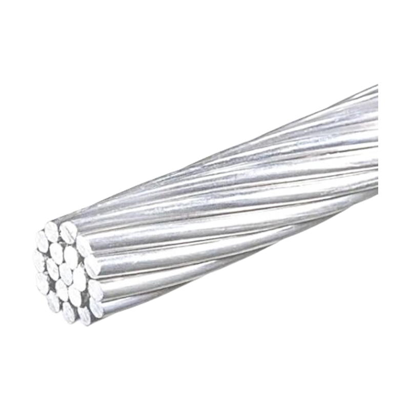
The conductor is the main current-carrying element. Copper tube conductors offer high electrical conductivity, strong short-circuit performance, and good connection reliability. Aluminum alloy conductors provide a lower-weight alternative and can be selected where reduced structural loading or easier handling is important. The conductor size and material are determined according to continuous current, short-circuit current, voltage level, temperature rise, installation configuration, and applicable technical requirements.
The conductor shielding layer is positioned around the metallic conductor. It helps smooth the conductor surface from an electrical perspective and creates a controlled transition between the conductor and the main insulation. By reducing sharp electrical irregularities, the shielding layer supports more uniform voltage distribution.
The primary insulation layer is generally based on EPDM rubber or a similar high-performance elastomeric insulation compound. This layer provides the main dielectric strength of the tubular busbar. EPDM is known for its resistance to weathering, ozone, ultraviolet radiation, moisture, and many chemical environments. Its flexibility also helps the busbar tolerate thermal expansion, vibration, and installation movement better than rigid insulation materials.
The insulation shielding layer surrounds the primary insulation and contributes to electric-field control. It provides a defined outer electrical surface and supports the integration of the metallic shield. A well-controlled insulation shield is particularly important at terminals, joints, bends, and other locations where electrical stress may otherwise become concentrated.
The metallic shielding layer is commonly formed using copper foil or another conductive shielding material. It helps control the external electric field and provides a route for induced or fault-related currents when properly connected to the grounding system. The shield design must be coordinated with the system grounding method and the specific project requirements.
The outer sheath is normally manufactured from a polyolefin polymer or another suitable protective compound. It protects the internal structure from abrasion, moisture, contamination, ultraviolet exposure, and handling damage. The outer sheath also provides a visible and durable external surface for installation identification and inspection.
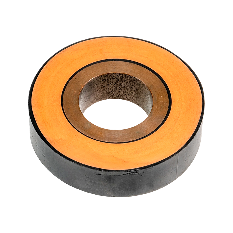
EPDM Silicone Rubber Tubular Bus Bar
2. Composite Shielded Insulation Design
The principal technical feature of the EPDM silicone rubber tubular bus bar is its composite shielded insulation design. A conventional insulated conductor may rely mainly on the quality and thickness of one insulation layer. A shielded tubular busbar uses several coordinated layers to manage both electrical and mechanical requirements.
In a medium- or high-voltage system, the electric field is not distributed uniformly simply because a conductor is covered with insulation. The conductor geometry, terminal shape, joint configuration, insulation thickness, shielding continuity, and nearby grounded objects all influence the electric field. If the field becomes concentrated at a connection or discontinuity, partial discharge, corona, accelerated aging, and insulation failure may occur.
The conductor shield helps create a smoother electrical boundary around the conductor. The primary insulation provides the main dielectric barrier, while the insulation shield defines the outer boundary of the insulation. Together, these layers reduce uncontrolled electric-field concentration and support predictable dielectric performance.
The metallic shield adds another important function. It helps contain the external electric field and can reduce the influence of nearby conductive objects. In a fully insulated tubular busbar system, this allows the product to be installed in locations where a bare busbar would require larger phase-to-phase and phase-to-ground clearances.
Layer adhesion and interface quality are essential to this design. The triple-layer co-extrusion process forms the conductor shielding, insulation, and insulation shielding in one coordinated production operation. This minimizes the possibility of loose interfaces and reduces the risk of air voids between layers. Consistent material feeding, temperature control, extrusion pressure, line speed, and cooling conditions are needed to achieve stable results.
2.1 Importance of Gapless Interfaces
A gap between insulation layers can become a location of increased electrical stress. Even a small air pocket may have a lower dielectric strength than the surrounding polymer insulation. Under operating voltage, the air pocket can experience intensified electrical stress and may become a source of partial discharge. Repeated discharge activity can gradually damage the surrounding insulation.
By forming multiple layers together, co-extrusion helps create a more integrated insulation body. The process does not eliminate the need for testing, material control, and careful joint installation, but it provides a strong manufacturing foundation for stable insulation performance.
Uniform insulation thickness is also important. Uneven thickness can cause the electric field to become unbalanced around the conductor. Automated extrusion equipment and process monitoring support better dimensional consistency than manual wrapping or uncontrolled secondary application methods.
2.2 EPDM-Based Insulation Characteristics
EPDM rubber is valued in electrical applications because it combines flexibility with resistance to outdoor aging. Properly formulated EPDM insulation can tolerate temperature variation, humidity, ozone, ultraviolet exposure, and chemical contamination. These characteristics make it suitable for equipment installed in substations, industrial plants, coastal regions, outdoor switchyards, wind power facilities, and other challenging locations.
The insulation system can be designed for a broad operating temperature range. The supplied product information identifies a typical working range of approximately minus 40 degrees Celsius to 120 degrees Celsius, subject to the exact material formulation, conductor size, installation method, and project specification. Actual continuous and emergency operating limits should always be confirmed through the product technical documentation.
EPDM insulation also has greater flexibility than ceramic insulation. This makes it more tolerant of vibration and thermal movement and simplifies the installation of long or irregular busbar routes. Its flexibility does not remove the need for correct support spacing and bend-radius control, but it can make system integration more practical.
3. Electrical and Mechanical Performance
The performance of a tubular busbar depends on the conductor material, cross-sectional area, insulation design, shielding arrangement, joint construction, ambient conditions, and installation configuration. A properly engineered EPDM silicone rubber tubular bus bar is designed to provide stable current carrying, controlled electric-field distribution, and reliable insulation under normal and abnormal operating conditions.
3.1 Current-Carrying Capability
Copper tubular conductors provide excellent conductivity and efficient heat dissipation. Their tubular geometry can offer a favorable balance between electrical performance, mechanical rigidity, and material utilization. Aluminum alloy conductors reduce weight and can provide an economical solution for certain current ratings. The selection between copper and aluminum should consider conductivity, temperature rise, mechanical loading, joint design, corrosion conditions, and total project cost.
The current-carrying capacity is not determined by conductor material alone. Heat dissipation is influenced by the insulation layers, ambient temperature, enclosure conditions, installation spacing, route orientation, and ventilation. In some standard configurations, tubular busbar systems can be designed for currents up to approximately 3,000 amperes, while larger ratings may be available through customized engineering.
Terminal adapters help connect the round tubular conductor to flexible expansion joints or other connection components. The adapter creates a smooth transition from the circular conductor to the connection interface. This reduces abrupt changes in geometry, assists current distribution, and helps limit temperature rise at the terminal.
3.2 Short-Circuit and Mechanical Strength
During a short circuit, conductors experience strong electromagnetic forces. A tubular conductor has useful mechanical rigidity and can be supported along a defined route. The complete busbar system must nevertheless be designed with suitable supports, clamps, expansion provisions, and clearances to withstand the expected short-circuit forces.
Copper tube conductors are especially suitable where high short-circuit strength and compact connections are required. Aluminum alloy conductors can also be applied when the structural design, connection method, and material compatibility are properly addressed. The final system should be verified against the specified short-circuit withstand requirements.
Thermal expansion is another mechanical consideration. Conductors and insulation materials expand at different rates as temperature changes. Flexible expansion joints, correctly designed supports, and suitable terminal adapters accommodate this movement. The use of expansion components reduces stress at fixed connection points and improves long-term operating reliability.
3.3 Insulation and Dielectric Strength
The supplied product information identifies a typical insulation breakdown strength of at least 25 kilovolts per millimeter for the EPDM silicone rubber insulation system. This figure should be understood as a material or design reference rather than a substitute for complete product testing. Final dielectric performance depends on insulation thickness, manufacturing quality, interface integrity, shielding continuity, joint installation, and environmental conditions.
Routine and type testing can include power-frequency withstand tests, insulation resistance tests, partial discharge tests, dimensional checks, material verification, and other assessments required by the project or applicable standards. Testing is particularly important for completed joints and terminations because these areas contain transitions in geometry and electric-field distribution.
4. Prefabricated Cold-Shrink Terminations and Joints
Terminations and intermediate joints are among the most important parts of a medium- or high-voltage busbar installation. Even when the main insulated tube has excellent dielectric performance, an improperly designed or installed joint can create electric-field concentration, leakage paths, mechanical weakness, or water ingress.
The EPDM silicone rubber tubular bus bar uses prefabricated cold-shrink components in selected terminal and intermediate joint designs. These components are prepared under controlled manufacturing conditions and installed without requiring external heat sources. The cold-shrink structure contracts around the prepared connection and creates a controlled interface.
4.1 Stress Cone Function
A stress cone changes the geometric shape of the insulation system near a voltage concentration point. This modifies the electric-field distribution and reduces the intensity of the field at the end of the conductive shield. By controlling the transition between shielded and unshielded regions, the stress cone helps reduce the likelihood of corona discharge and partial discharge.
The stress cone also reduces the risk of localized insulation damage. A smoother field transition can slow the development of electrical treeing and other aging mechanisms. The effectiveness of the design depends on correct component selection, clean preparation, proper positioning, and complete conformity between the joint components and the busbar.
4.2 Intermediate Joint Construction
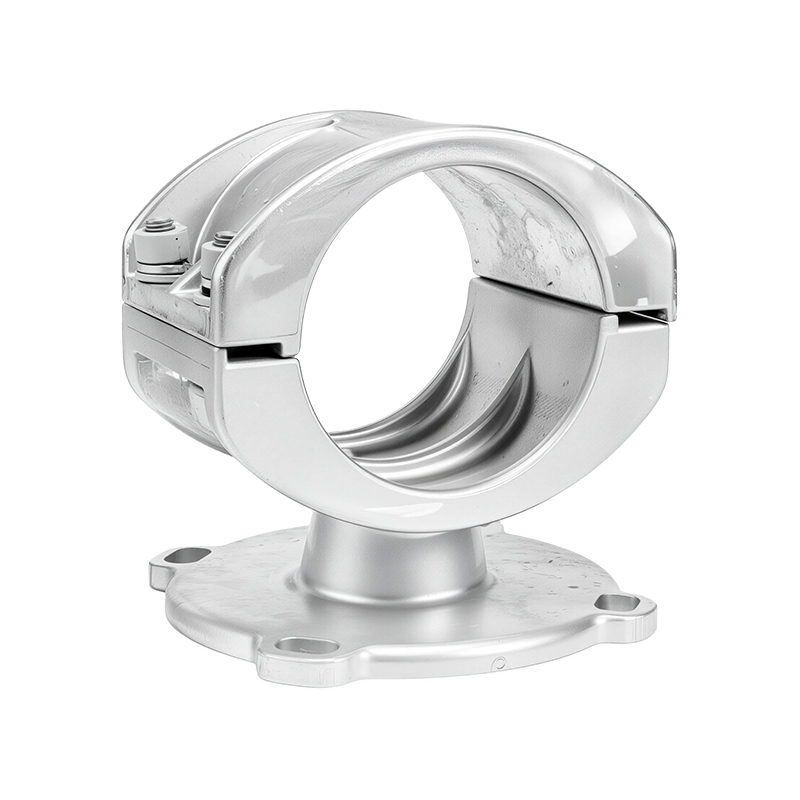
The intermediate joint design uses a stainless steel inner sleeve to establish direct contact between conductor sections. Two semicircular connecting busbars are placed externally, and specialized stainless steel C-clamp tools are used to tighten and secure the connection. The connection is then welded or fixed according to the specified production and installation procedure.
This arrangement is intended to maintain current-carrying capacity while reducing conductor deformation. A stable mechanical connection is important because looseness, uneven pressure, or conductor damage can increase contact resistance. Increased contact resistance produces additional heat and may lead to progressive deterioration during long-term operation.
After the electrical connection is completed, the joint is covered by the appropriate insulation and shielding components. The final joint should maintain continuity of the insulation shield and metallic shield. Waterproofing is applied where required, allowing the busbar to tolerate short-term immersion or operation in wet conditions after the specified treatment has been completed.
4.3 Joint Installation Benefits
Prefabricated cold-shrink joints have a compact structure and can be installed without the heating equipment required by heat-shrink systems. This can be useful in substations, cable trenches, equipment rooms, and other areas where access is restricted or fire control is important.
The components are designed to provide repeatable performance when installed according to the approved procedure. Their compact form helps reduce the total installation footprint and can simplify routing around switchgear, transformers, and structural obstacles.
Cold-shrink joint technology does not eliminate the need for skilled installation. The conductor must be prepared accurately, the insulation surface must be clean, the shield must be positioned correctly, and the components must be installed in the specified sequence. Installation records and inspection checkpoints should be maintained for critical power projects.
5. Advantages Compared with Conventional Insulated Busbars
The EPDM silicone rubber tubular bus bar offers a combination of electrical, environmental, and mechanical benefits that can make it more suitable than some conventional insulated busbar alternatives. The exact comparison depends on the competing product, voltage class, current rating, installation environment, and project specifications.
| Performance Category | EPDM Silicone Rubber Tubular Bus Bar | PVC Insulated Busbar | Ceramic Insulated Busbar | Conventional Bare Busbar |
|---|---|---|---|---|
| Insulation structure | Composite shielded insulation with conductor and insulation shielding | Usually a polymer insulation layer without the same high-voltage shield arrangement | Rigid ceramic insulation components | Requires external insulation clearances or barriers |
| Weather resistance | Strong resistance to ultraviolet radiation, ozone, moisture, and many chemicals | May experience accelerated aging under prolonged ultraviolet exposure | Good environmental resistance but vulnerable to impact and brittleness | Conductor is exposed to contamination and weather |
| Flexibility | Flexible elastomeric insulation with adaptable joint systems | Generally flexible but limited by voltage and temperature requirements | Low flexibility and sensitive to mechanical shock | Rigid conductor route with exposed connections |
| Electric-field control | Conductor shield, insulation shield, metallic shield, and stress-controlled joints | Depends primarily on insulation geometry and system design | Controlled through component geometry and clearances | Requires large clearances and careful arrangement |
| Typical service-life potential | Approximately 25 to 35 years when correctly designed, manufactured, installed, and maintained | Approximately 10 to 15 years in demanding exposure conditions, depending on formulation | Approximately 20 to 25 years, subject to mechanical integrity | Highly dependent on environmental contamination and maintenance |
| Space requirements | Compact and suitable for confined routes | Compact in lower-voltage applications | Requires careful support and clearance planning | Usually requires larger safety clearances |
5.1 Compared with PVC Insulation
PVC-insulated products can be economical and effective in appropriate low-voltage and moderate-environment applications. However, PVC may be less suitable for long-term outdoor exposure, high temperatures, strong ultraviolet radiation, or demanding high-voltage electric-field conditions. EPDM-based insulation generally provides better resistance to ozone, ultraviolet radiation, and weathering.
The shielded construction of the EPDM tubular busbar also provides a more controlled electric-field arrangement than a basic PVC-insulated conductor. This makes it better suited to medium- and high-voltage systems where insulation coordination and partial-discharge control are central design concerns.
5.2 Compared with Ceramic Insulation
Ceramic insulation can provide strong dielectric performance and excellent resistance to many environmental conditions. Its principal limitation is mechanical brittleness. Ceramic components can be damaged by impact, vibration, uneven loading, or mishandling during installation. They also provide limited flexibility when the route requires thermal movement or complex alignment.
EPDM silicone rubber insulation offers a more flexible and impact-tolerant alternative. It can accommodate movement more effectively and is easier to integrate into routes with moderate bends or connection transitions. While ceramic systems remain valuable in many applications, elastomeric insulation can provide a better balance of electrical reliability and installation adaptability.
5.3 Compared with Bare Busbars
Bare busbars are widely used in substations and switchyards, but they require sufficient electrical clearance from other phases, grounded structures, personnel, and adjacent equipment. They may also require extensive support structures and protective barriers. Dust, salt, moisture, and industrial contamination can reduce surface insulation distances and increase maintenance requirements.
A fully insulated tubular busbar reduces exposure of the conductor to the surrounding environment. Its shielded construction permits more compact installation and can improve personnel safety when the system is correctly grounded, guarded, and installed according to the applicable requirements. The product is especially useful where space is limited or where the route passes through a cable trench, equipment room, or cable mezzanine.
6. Environmental and Operational Advantages
Power equipment often operates under changing environmental conditions. Outdoor substations may be exposed to rain, snow, solar radiation, dust, salt fog, and temperature cycling. Industrial plants can introduce chemical vapors, conductive dust, oil mist, and vibration. Renewable energy facilities may be located in remote areas where maintenance access is limited.
The EPDM silicone rubber tubular bus bar is designed to address these challenges through its sealed insulation system and weather-resistant materials. The outer sheath protects the internal layers, while the EPDM insulation maintains elasticity across a broad temperature range. The metallic shield and waterproofed joints contribute to the overall environmental protection of the complete assembly.
In coastal environments, salt contamination can increase the risk of surface leakage and corrosion. A fully insulated and properly sealed busbar reduces direct exposure of the conductor and helps limit the accumulation of conductive contamination on energized surfaces. Material selection, grounding, joint sealing, and routine inspection remain necessary for reliable operation.
In chemical plants, the product can be specified with materials suitable for the expected chemical exposure. The exact compatibility must be evaluated against the specific substances, concentrations, temperature, and exposure duration. EPDM provides good resistance to many environmental contaminants, but no insulation material should be selected without a project-specific compatibility assessment.
In wind power and solar power installations, compact routing and reduced maintenance can be important. Tubular busbars can connect transformers, switchgear, converters, and collection systems while accommodating restricted equipment layouts. Their shielded construction also helps manage electromagnetic and electric-field requirements within compact power equipment areas.
7. Typical Application Solutions
7.1 Main Transformer to Control or Switchgear Room
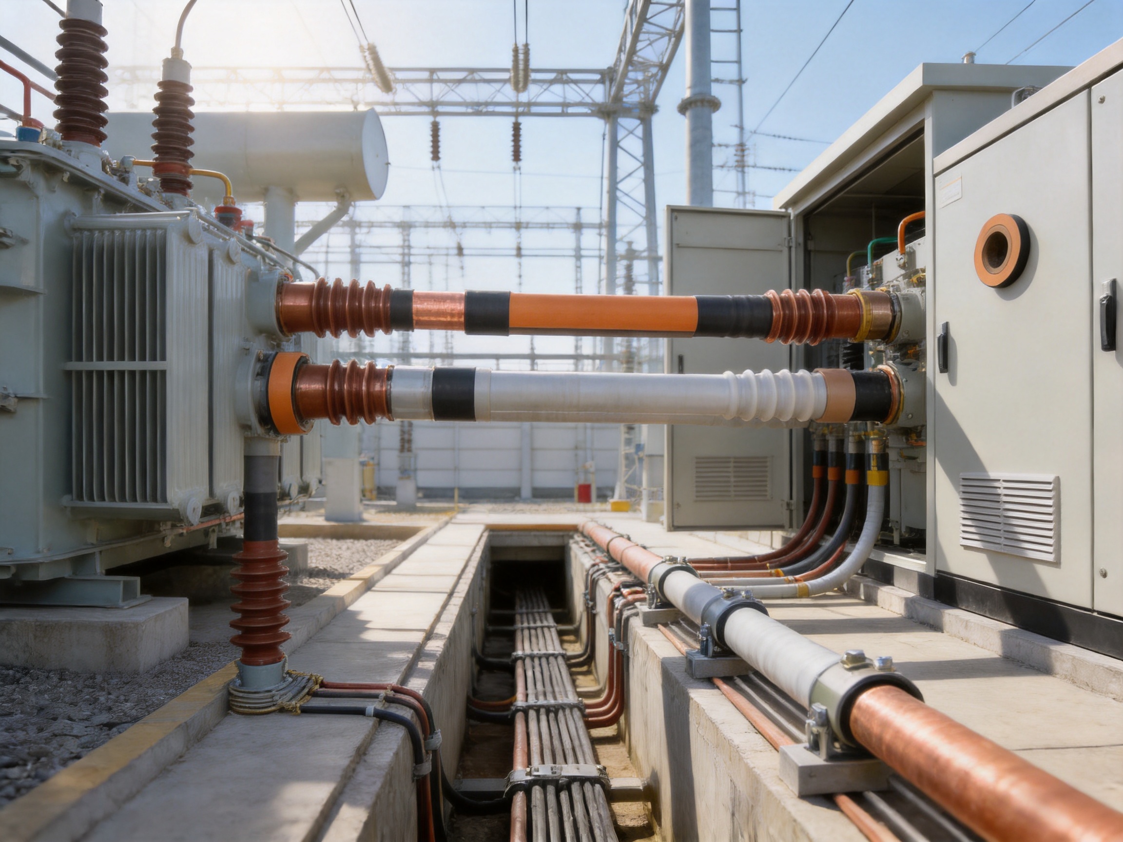
One of the most common applications is the connection between a main transformer and a low-voltage or medium-voltage switchgear room. The tubular busbar can be routed directly from the transformer terminal to the switch cabinet connection. This arrangement provides a clear and organized power path and is suitable for large current requirements.
The route may be installed indoors, outdoors, or through a protected transition area. Terminal adapters and flexible expansion joints help accommodate differences between the transformer connection and the switchgear connection. The fully insulated version is useful where the route passes near building structures or other equipment.
7.2 Cable Trench or Cable Mezzanine Installation
A tubular busbar can be installed through an underground cable trench or cable mezzanine to connect transformers, switchgear, and distribution equipment. This approach is useful where overhead routing is undesirable or where the building design provides a dedicated lower-level service space.
The compact design helps simplify routing in confined areas. Waterproofed joints can be specified for locations where temporary water accumulation or high humidity is possible. Drainage, support arrangement, ventilation, and access for inspection should be considered during the engineering stage.
7.3 Switchgear Top or Bottom Connection
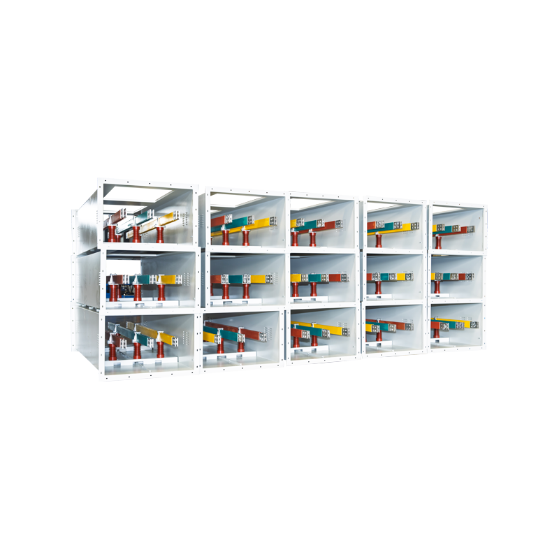
Depending on the switchgear layout, the busbar can enter from the top or bottom of the cabinet. A top connection may be convenient where the transformer or overhead route is aligned with the switchgear. A bottom connection can be used through a cable trench or mezzanine when the site layout requires concealed routing.
The chosen connection method should consider bending space, terminal accessibility, expansion movement, grounding, maintenance clearance, and the manufacturer’s minimum installation radius. A complete layout drawing should be reviewed before fabrication so that the busbar sections and joint locations match the actual equipment positions.
7.4 Intelligent Monitoring
Modern tubular busbar systems can be combined with monitoring solutions that collect data related to temperature, current, insulation condition, joint status, and other operating parameters. An intelligent monitoring system can support early warning and reduce the dependence on periodic manual inspection alone.
Monitoring does not replace correct design or routine testing. Instead, it adds operational visibility. Temperature sensors near joints and terminals may help identify abnormal contact resistance or overload. Data analysis can support predictive maintenance and allow operators to prioritize inspection of critical sections.
8. Manufacturing Process and Quality Control
Manufacturing quality directly influences the electrical and mechanical reliability of an insulated tubular busbar. The product requires coordination between conductor fabrication, polymer compounding, extrusion, shielding, joint production, machining, assembly, and testing.
8.1 Engineering and Specification Review
Production begins with a technical review of the project requirements. Engineers evaluate voltage level, continuous current, short-circuit withstand, route length, conductor material, ambient temperature, installation environment, terminal configuration, joint positions, grounding method, and applicable standards.
The engineering team also reviews the transformer and switchgear interface dimensions. Accurate interface data is essential because tubular busbars are often manufactured for a specific installation. Incorrect terminal dimensions or route geometry can create installation delays and unnecessary field modifications.
8.2 Conductor Preparation
Copper or aluminum tube conductors are prepared according to the required cross-sectional dimensions and connection design. CNC machining can be used to create accurate terminal interfaces, drilling patterns, transition components, and other precision features. Dimensional control at this stage supports correct alignment during final assembly.
Before extrusion or assembly, conductor surfaces must be inspected and prepared. Contamination, oxidation, burrs, or dimensional irregularities can affect shield adhesion and electrical contact quality. The conductor is cleaned and checked according to the established production procedure.
8.3 Polymer Material Control
EPDM rubber, shielding compounds, polyolefin sheath materials, and other polymer components must be stored and handled under controlled conditions. Material identification, batch traceability, shelf-life control, and formulation verification reduce the risk of unintended variation.
Compounding parameters influence elasticity, dielectric strength, thermal aging, adhesion, and weather resistance. The manufacturing system should maintain records for material batches and processing conditions so that finished products can be traced to their raw materials and production records.
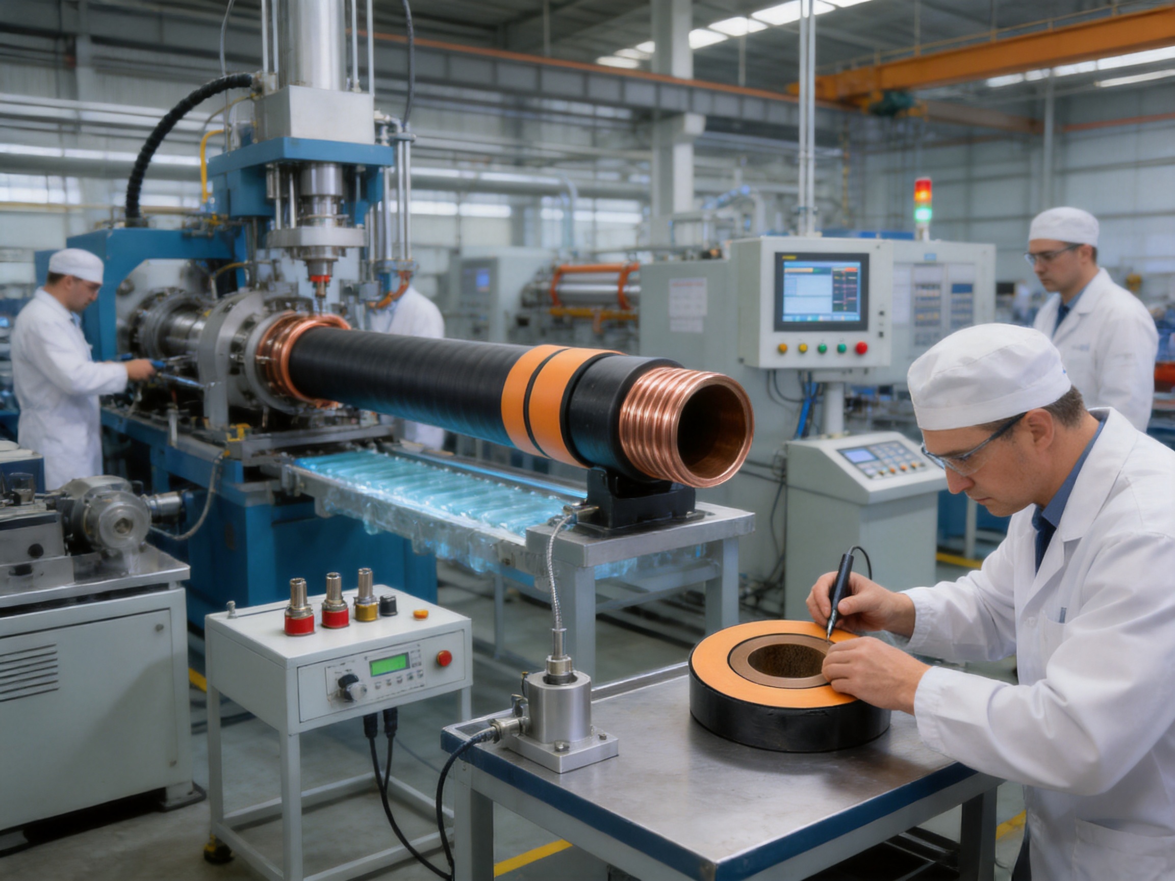
8.4 Triple-Layer Co-Extrusion
The core production operation is the triple-layer co-extrusion of the conductor shield, primary insulation, and insulation shield. Multiple extrusion channels feed the selected materials around the conductor in a coordinated process. Temperature, pressure, speed, concentricity, and cooling must be controlled continuously.
The objective is to create a stable, uniform, and closely integrated insulation structure. Process deviations can cause eccentricity, surface defects, thickness variation, poor interface bonding, or dimensional instability. Automated line control and in-process measurements help identify such deviations before the product reaches final assembly.
After extrusion, the insulated tube is cooled under controlled conditions. Cooling that is too rapid, too slow, or uneven may affect dimensional stability and residual stress. The finished section is then inspected for surface quality, diameter, insulation thickness, shield continuity, and other specified characteristics.
8.5 Metallic Shield and Outer Sheath
The metallic shielding layer is applied and connected in accordance with the design requirements. Copper foil or another conductive shield must be continuous and properly terminated. Shield continuity is essential for electric-field control and grounding performance.
The external polyolefin sheath is applied to protect the internal structure. The sheath must be uniform and free from cuts, pinholes, inclusions, and other defects that could allow moisture penetration. Marking and identification may be applied to support installation and maintenance.
8.6 Joint and Terminal Manufacturing
Terminal adapters, stress cones, cold-shrink components, stainless steel inner sleeves, semicircular connecting busbars, C-clamps, and waterproofing materials are manufactured or assembled according to controlled drawings and procedures.
Joint components require dimensional accuracy because small deviations can influence contact pressure, shield continuity, electric-field distribution, and waterproofing. Components should be checked before dispatch, and installation kits should be packaged with clear identification and assembly instructions.
8.7 Testing and Inspection
Finished busbars can undergo high-voltage withstand testing, insulation resistance testing, partial-discharge evaluation, conductor resistance measurement, dimensional inspection, mechanical verification, and routine visual inspection. The exact test program depends on the product type, voltage class, customer specification, and applicable standards.
Joint assemblies and terminations deserve particular attention because they contain transitions between different structural elements. Testing and inspection should verify that the shield system is continuous, the conductor connection is secure, and the insulation system has no visible or measurable defect.
Jiangsu Wopeng Power Technology Co., Ltd. operates production capabilities that include vacuum casting systems, CNC machining equipment, automated assembly technologies, and standardized inspection processes. The company also cooperates with third-party testing institutions when independent validation is required for a project.
9. Manufacturer Strengths and Customization Capability
A reliable tubular busbar supplier must provide more than a standard product catalog. Each project may require different conductor sizes, voltage levels, route geometries, terminal arrangements, expansion provisions, joint positions, grounding methods, and environmental protections.
Jiangsu Wopeng Power Technology Co., Ltd. was founded in 2018 and specializes in high- and low-voltage busbar systems. Its product portfolio covers 35-kilovolt epoxy resin vacuum-cast tubular busbars, low-voltage cast resin busways, copper and aluminum tubular busbars, wind power tubular busbars, compact busbar systems, and sliding contact line systems.
The company serves power generation, substations, wind energy, industrial manufacturing, rail transit, and large commercial facilities. Its products operate across more than 17 provinces and in multiple industrial sectors, providing experience in different environmental and installation conditions.
Its engineering, technical, and production teams support product development from initial electrical calculation through manufacturing, testing, shipment, and installation guidance. This integrated approach is valuable for projects where the tubular busbar must interface with equipment from different manufacturers.
Customization may include conductor material selection, current rating, insulation thickness, shield configuration, outer sheath material, terminal adapter geometry, joint structure, route segmentation, expansion joint arrangement, waterproofing, monitoring, and special environmental protection.
OEM production is also available for customers that require private labeling, project-specific documentation, customized dimensions, or integration into a broader power equipment package. The supplier’s ability to combine engineering design and production reduces communication gaps between the technical specification and the finished product.
10. Selection Guidelines for Project Engineers
Choosing an EPDM silicone rubber tubular bus bar should begin with the electrical requirements. The rated voltage, operating voltage, maximum continuous current, short-circuit current, frequency, insulation level, and grounding system must be defined before the product is selected.
The installation environment should then be assessed. Indoor, outdoor, underground, coastal, high-altitude, chemical, dusty, humid, and vibration-prone locations may require different sheath materials, sealing arrangements, support designs, or inspection intervals.
Route geometry is equally important. Engineers should identify straight sections, bends, terminal positions, expansion points, intermediate joints, support locations, and access areas. A detailed route drawing reduces the risk of field modifications and helps optimize the number and location of joints.
Conductor selection should consider both electrical and mechanical requirements. Copper may be selected for maximum conductivity and compactness, while aluminum alloy may be preferred for lower weight. The connection design must be compatible with the selected conductor and should account for thermal expansion, contact pressure, oxidation control, and maintenance access.
Customers should request technical documents that include product drawings, current ratings, insulation data, test reports, joint installation instructions, material information, and quality records. A professional supplier should be able to explain the basis of its performance data and identify the conditions under which the ratings apply.
11. Installation and Maintenance Considerations
Installation should be performed by qualified personnel who understand medium- and high-voltage equipment. The busbar sections must be handled carefully to prevent damage to the outer sheath, terminal components, and insulation surfaces.
Before installation, each section should be checked for transport damage, correct identification, dimensional conformity, and completeness of the accessory kit. Storage areas should be dry, clean, and protected from direct sunlight, chemicals, sharp objects, and excessive mechanical loading.
During installation, the specified support spacing and bend radius must be followed. Excessive bending can affect conductor alignment, insulation geometry, or shield continuity. The busbar should not be forced into position by applying uncontrolled mechanical stress to the terminals.
Joint preparation must follow the approved procedure. Conductor surfaces should be clean and correctly prepared. Stainless steel sleeves, semicircular connecting busbars, C-clamps, stress cones, shielding components, and waterproofing materials must be installed in the specified sequence.
After installation, the system should undergo the required electrical tests before energization. Inspection should confirm grounding continuity, terminal tightness, phase identification, support security, shielding connections, and clearance from surrounding structures.
Routine maintenance may include thermal imaging, visual inspection, monitoring data review, grounding checks, joint inspection, and periodic electrical testing. Particular attention should be given to terminal areas and intermediate joints because these are the most complex sections of the system.
12. Frequently Asked Questions
Q1: What is an EPDM silicone rubber tubular bus bar?
An EPDM silicone rubber tubular bus bar is a medium- or high-voltage insulated conductor system consisting of a copper or aluminum tubular conductor, conductor shielding, EPDM-based primary insulation, insulation shielding, metallic shielding, and a protective outer sheath. It is designed to transmit electrical current while controlling the electric field and protecting the conductor from environmental exposure.
Q2: What voltage range is this product suitable for?
The product is mainly intended for medium- and high-voltage applications, including systems in the approximate 10-kilovolt to 35-kilovolt range. Higher-voltage designs may be developed through project-specific engineering, subject to insulation coordination, testing, and applicable technical requirements.
Q3: Is the busbar available with copper and aluminum conductors?
Yes. Copper tubular conductors are suitable where high conductivity, compact size, and strong short-circuit performance are important. Aluminum alloy conductors can reduce weight and may offer cost advantages. The final selection should consider current rating, mechanical requirements, connection technology, and environmental conditions.
Q4: What is the purpose of triple-layer co-extrusion?
Triple-layer co-extrusion forms the conductor shield, primary insulation, and insulation shield in a coordinated process. It helps create tight interfaces, consistent insulation thickness, and reduced air-gap risk. The process supports stable electric-field control and improved insulation reliability.
Q5: How does the product control the electric field?
The conductor shield smooths the electrical boundary around the conductor, while the insulation shield and metallic shield define the outer electrical boundary. Prefabricated cold-shrink terminations use stress cones to change the geometry at voltage concentration points and reduce electric-field intensity.
Q6: Can it be installed outdoors?
Yes. The EPDM-based insulation and protective outer sheath provide resistance to ultraviolet radiation, ozone, moisture, temperature variation, and many environmental contaminants. Outdoor projects still require appropriate support, grounding, waterproofing, clearances, and inspection procedures.
Q7: Can it operate in a wet or temporarily submerged location?
Intermediate joints can be specially waterproofed so that the busbar may operate briefly while submerged, according to the approved product design and installation procedure. Permanent immersion, severe flooding, or continuous underwater service should be evaluated separately with the supplier.
Q8: What current can the tubular busbar carry?
Current capacity depends on conductor material, conductor dimensions, insulation design, ambient temperature, installation method, and allowable temperature rise. Standard configurations may support currents up to approximately 3,000 amperes, while larger ratings can be engineered for specific projects.
Q9: Why are stress cones used in the terminations?
Stress cones modify the geometric transition between shielded and unshielded sections. This redistributes the electric field, reduces localized stress, lowers the possibility of corona or partial discharge, and helps protect the insulation near the termination.
Q10: What information should be provided when requesting a quotation?
Customers should provide the system voltage, rated current, short-circuit level, conductor preference, route drawing, total length, number of bends, terminal equipment details, joint locations, installation environment, grounding method, monitoring requirements, and applicable standards. Complete information allows the supplier to design accurate sections and accessories.
Q11: What testing should be requested from the supplier?
Typical documentation may include routine high-voltage withstand results, insulation resistance data, partial-discharge test results where applicable, conductor resistance measurements, dimensional inspection records, material information, and product conformity documentation. The final test plan should match the project specification and applicable standards.
Q12: Why choose an experienced tubular busbar manufacturer?
An experienced manufacturer can coordinate electrical design, conductor fabrication, extrusion, joint engineering, CNC machining, assembly, testing, and project documentation. This integrated capability helps reduce interface errors and provides better support for customized routes, unusual environmental conditions, and high-current applications.
13. Conclusion
The EPDM silicone rubber tubular bus bar is a fully insulated power transmission solution that combines a tubular copper or aluminum conductor with a composite shielded insulation structure. Its triple-layer co-extrusion process, EPDM-based insulation, metallic shielding, prefabricated cold-shrink terminations, and waterproofed joint options provide a balanced combination of electrical performance, environmental resistance, compactness, and installation flexibility.
Compared with PVC-insulated products, the system offers stronger resistance to demanding outdoor conditions and higher-voltage electric-field requirements. Compared with ceramic insulation, it provides greater flexibility and improved tolerance of vibration and mechanical handling. Compared with bare busbars, it reduces conductor exposure and can support more compact, organized, and fully insulated installations.
The quality of the complete system depends on more than the main insulated tube. Conductor selection, extrusion control, shield continuity, terminal design, joint installation, grounding, testing, and maintenance must all be managed as part of one coordinated engineering process.
With capabilities in polymer extrusion, vacuum casting, CNC machining, automated assembly, high-voltage testing, and customized busbar engineering, Jiangsu Wopeng Power Technology Co., Ltd. provides solutions for substations, industrial plants, renewable energy stations, rail transit, commercial facilities, and other critical power applications. Properly designed and manufactured, the EPDM silicone rubber tubular bus bar can provide a durable and efficient connection for modern medium- and high-voltage distribution systems.
References
1. IEC 62271 Series, High-Voltage Switchgear and Controlgear.
2. IEC 60502 Series, Power Cables with Extruded Insulation and Their Accessories.
3. IEC 60840, Power Cables with Extruded Insulation and Their Accessories for Rated Voltages Above 30 kV up to 150 kV.
4. IEC 60909 Series, Short-Circuit Currents in Three-Phase AC Systems.
5. IEEE Std 48, Standard for Test Procedures and Requirements for Alternating-Current Cable Terminations Used on Shielded Cables.
6. IEEE Std 404, Standard for Extruded and Laminated Dielectric Shielded Cable Joints Rated 2.5 kV Through 500 kV.
7. International standards and manufacturer technical specifications for EPDM electrical insulation, shielded busbar systems, high-voltage joints, and power distribution equipment.
8. Product engineering, manufacturing, testing, and application materials for insulated tubular busbar systems supplied by Jiangsu Wopeng Power Technology Co., Ltd.
Product: EPDM Silicone Rubber Tubular Bus Bar




-
 +86-180 3625 3000
-
 admin@wpbusbar.com
-
 No. 8, Yanjin Road, Chengxi Industrial Park, Shanyang Town, Baoying County, Yangzhou City, Jiangsu Province, China
Copyright © Jiangsu Wopeng Power Technology Co., Ltd.
All Rights Reserved.
 Custom Insulated Bus Bar Manufacturer
Tubular Busbar System Factory