

 EN

 English
 русский
 Français
 Español
 عربى

Post Insulators for Reliable Medium- and High-Voltage Busbar Systems
Content
- 1 1. What Is a Post Insulator?
- 2 2. Role in Insulated Tubular Busbar Systems
- 3 3. Main Technical Advantages
- 4 4. Material Options for Post Insulators
- 5 5. Comparison with Conventional Rectangular Busbar Arrangements
- 6 6. Manufacturing Process and Quality Control
- 7 7. Why Choose an Integrated Manufacturing Partner?
- 8 8. Product Advantages over Conventional Alternatives
- 9 9. Application Areas
- 10 10. Installation Recommendations
- 11 11. Maintenance and Service Life
- 12 12. Frequently Asked Questions
- 12.1 Q1: What is the main purpose of a post insulator?
- 12.2 Q2: Can tubular busbars eliminate post insulators completely?
- 12.3 Q3: Which material is best for a post insulator?
- 12.4 Q4: What voltage levels can post insulators support?
- 12.5 Q5: What short-circuit current can a tubular busbar withstand?
- 12.6 Q6: Are post insulators suitable for polluted areas?
- 12.7 Q7: Can the products be customized?
- 12.8 Q8: What tests should be requested before delivery?
- 12.9 Q9: How should a post insulator be maintained?
- 12.10 Q10: Why purchase a post insulator from a busbar manufacturer?
- 13 13. Selecting the Right Supplier
- 14 14. Conclusion
- 15 References
- 16 Product: Post Insulator
Post insulators are essential components in electrical power systems because they provide mechanical support and electrical isolation for energized conductors, busbars, and equipment. They are used in substations, switchgear assemblies, distribution cabinets, transformer stations, renewable energy facilities, industrial plants, and other installations where reliable insulation and stable conductor positioning are required.
In modern power transmission and distribution projects, a post insulator must perform more than a basic supporting function. It must withstand operating voltage, short-circuit forces, mechanical loading, vibration, temperature variation, humidity, pollution, and, in some cases, seismic activity. It must also be compatible with the busbar structure, support brackets, enclosure arrangement, installation environment, and maintenance strategy of the complete electrical system.
For this reason, post insulators should be selected as part of an integrated busbar solution rather than as isolated components. In tubular busbar systems, structural design can reduce the number of traditional support points and simplify the overall arrangement. However, post insulators remain valuable wherever electrical clearance, mechanical restraint, conductor support, or equipment connection requires a dedicated insulating component.
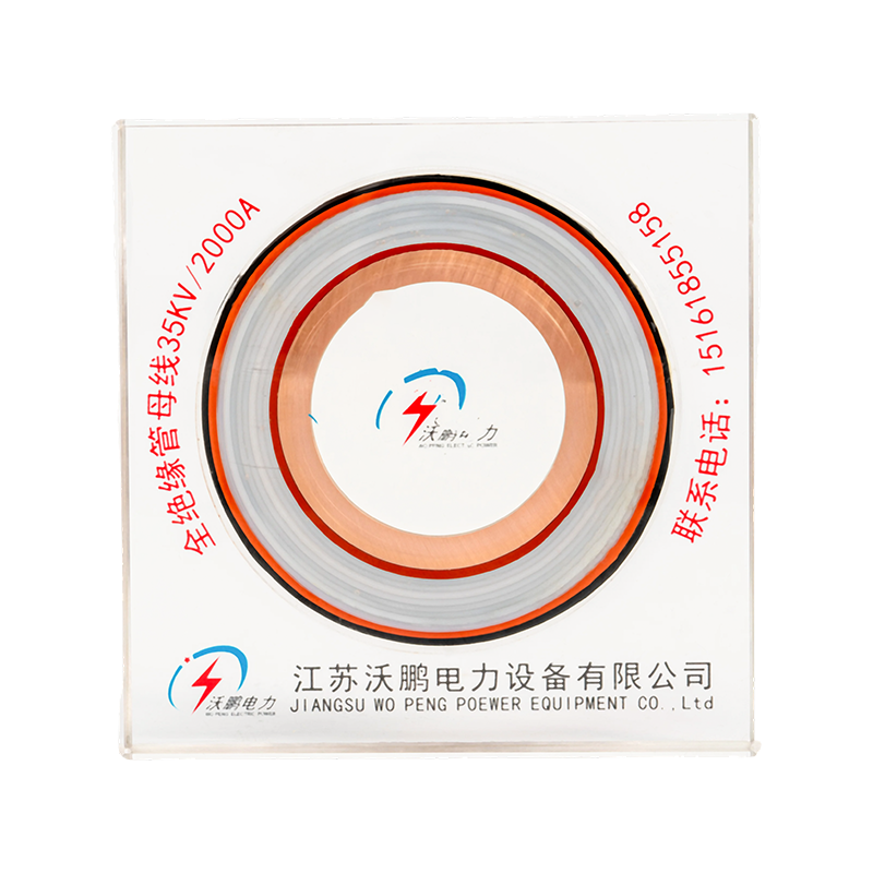
Jiangsu Wopeng Power Technology Co., Ltd. develops and manufactures busbar systems and related electrical equipment for demanding industrial and utility applications. Its product range includes insulated tubular busbars, aluminum and copper tubular busbars, epoxy resin cast busbars, low-voltage busway systems, wind power tubular busbars, compact busbar systems, and sliding contact line systems. Supported by engineering experience, modern production equipment, standardized inspection, and customized OEM capability, the company provides post insulator and busbar solutions for low-voltage, medium-voltage, and high-voltage applications.
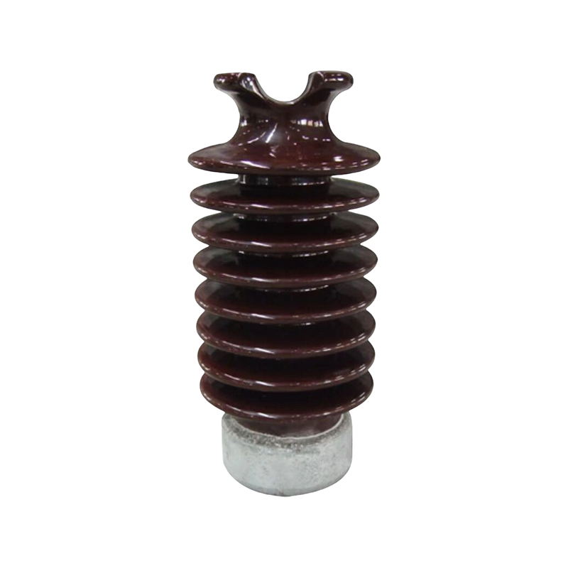
Post Insulator
1. What Is a Post Insulator?
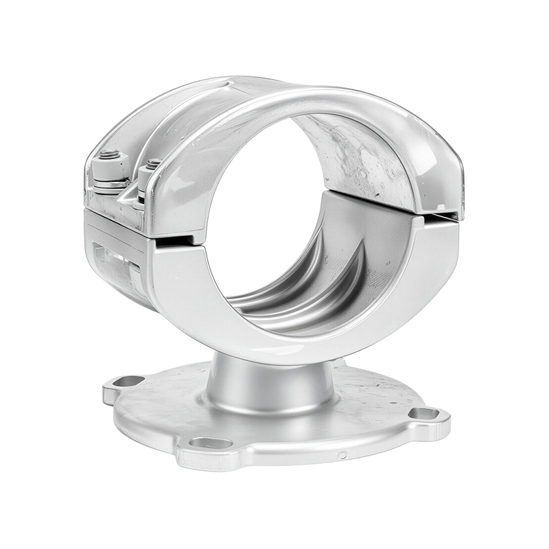
A post insulator is a rigid insulating device designed to support electrical conductors while maintaining a safe electrical separation between energized parts and grounded structures. Unlike suspension insulators, which are normally arranged in strings and allow a conductor to hang, post insulators maintain a fixed position. Their rigid shape enables them to support busbars, conductors, disconnecting devices, switchgear components, and other electrical assemblies.
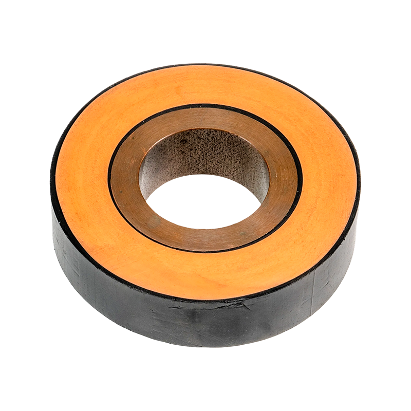
A typical post insulator consists of an insulating body and one or more metal connection fittings. The insulating body may be manufactured from porcelain, toughened glass, epoxy resin, silicone rubber, or another qualified electrical insulating material. The metal fittings provide connection points for the busbar or conductor at the top and for the supporting structure at the bottom.
The insulating body must provide sufficient dielectric strength to resist normal operating voltage, temporary overvoltage, lightning impulses, switching impulses, and power-frequency test voltage. At the same time, the complete component must resist mechanical forces caused by conductor weight, wind, vibration, thermal expansion, and short-circuit current.
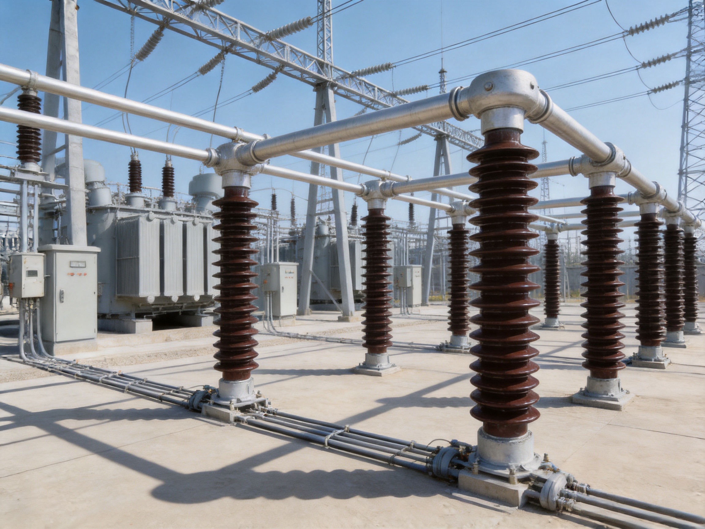
Post insulators are commonly installed in indoor switchgear, outdoor substations, busduct systems, transformer connections, capacitor banks, reactors, distribution cabinets, and power generation equipment. The correct model depends on rated voltage, insulation level, creepage distance, mechanical load, mounting arrangement, environmental pollution, altitude, temperature, and the required service life.
Core Functions of a Post Insulator
The first function is electrical isolation. A post insulator prevents current from flowing between an energized busbar and a grounded steel structure. Its insulation resistance must remain stable during normal operation and under environmental conditions such as humidity, dust, salt, and industrial contamination.
The second function is mechanical support. A rigid post insulator holds a conductor or busbar in a defined position. This helps maintain phase-to-phase and phase-to-ground clearances and prevents excessive movement during operation.
The third function is short-circuit force resistance. When a short circuit occurs, large electrodynamic forces can act on parallel conductors. The post insulator and its mounting structure must withstand these forces without cracking, excessive deflection, loosening, or permanent deformation.
The fourth function is system integration. A post insulator must fit the dimensions, connection holes, bracket design, conductor geometry, and installation tolerances of the complete busbar assembly. A well-designed component reduces installation difficulty and helps maintain consistent electrical clearances.
2. Role in Insulated Tubular Busbar Systems
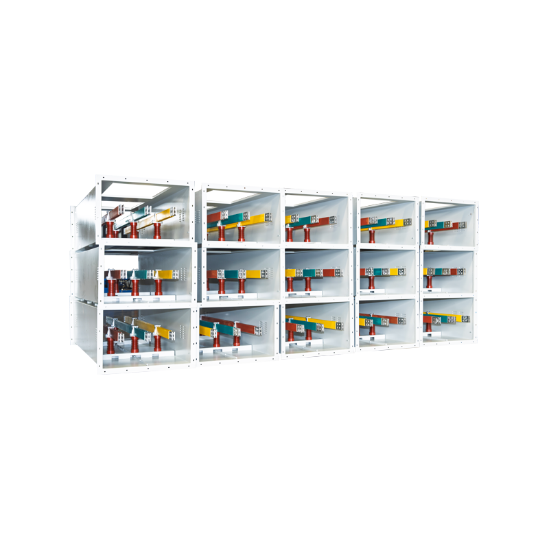
Insulated tubular busbar systems use tubular conductors and insulating structures to transmit high currents in a compact and mechanically robust arrangement. Depending on the system design, the tubular busbar may be covered, cast, supported, or directly connected to equipment and structural supports. The system can be used in substations, power plants, wind power installations, industrial facilities, and high-current distribution networks.
In some insulated tubular busbar designs, structural optimization reduces the need for conventional post insulators. The tubular busbar can be fixed directly to steel structures or concrete supports using dedicated brackets. This arrangement can simplify the support system, reduce the number of individual components, and improve installation efficiency.
Eliminating or reducing post insulators does not mean that insulation and mechanical support are no longer necessary. Instead, these functions are integrated into the tubular busbar structure, cast insulation, external support brackets, or specially engineered connection assemblies. Post insulators are still used where a separate rigid insulating support is needed, particularly at transitions, equipment terminals, outdoor sections, and locations requiring additional mechanical restraint.
The main benefit of this integrated approach is structural simplification. Traditional arrangements may require numerous post insulators, busbar fittings, wall bushings, foundations, and alignment points. A tubular busbar system can reduce these requirements by using a continuous, mechanically strong conductor with standardized brackets and direct equipment connections.
For example, under a short-circuit current of 50 kA, a Φ100 × 6 mm tubular busbar can achieve a suspended span of up to 9 meters in a suitable design. When supported by busbar brackets, the span can reach up to 13 meters. These values demonstrate the high mechanical capability of tubular conductors compared with conventional rectangular busbar arrangements, although the final allowable span must always be verified through project-specific calculations.
The allowable stress of the tubular busbar can be approximately four times that of a comparable rectangular busbar under relevant design conditions. The circular cross-section distributes mechanical stress efficiently and provides high resistance to bending and short-circuit forces. This can create a more open layout, reduce the number of support foundations, and improve access around the electrical equipment.
Support Spacing and Bracket Arrangement
Exposed tubular busbar systems generally use dedicated support brackets. A support spacing of not less than 275 mm is applied where required by the design to maintain electrical clearance and mechanical stability. Fixed brackets should be installed for spans ranging from 6 to 13 meters, depending on conductor size, thermal expansion, short-circuit conditions, support configuration, and project standards.
The support arrangement must account for conductor expansion and contraction. A system may include fixed supports, sliding supports, expansion joints, and flexible equipment connections. The purpose is to prevent thermal movement from transferring excessive force to the post insulator, busbar terminal, switchgear bushing, or transformer connection.
Installation tolerances are also important. The support structure must be level and aligned, and connection surfaces must be clean and free of mechanical damage. Correct alignment prevents local stress concentration and ensures that phase spacing remains within the specified range.
3. Main Technical Advantages
High Mechanical Strength
A major advantage of a properly designed post insulator and tubular busbar assembly is its resistance to mechanical loading. Short-circuit current creates electromagnetic forces that increase rapidly as current rises. In high-current systems, these forces can be more critical than the static weight of the conductor.
Rigid post insulators help control conductor movement and transfer mechanical loads to the supporting structure. When combined with a high-strength tubular conductor, they support longer spans and allow the designer to reduce the quantity of brackets, foundations, and fittings. This can be particularly valuable in substations and industrial plants where floor space is limited.
Mechanical performance depends on more than the nominal strength of the insulating body. The metal fittings, cement or adhesive interface, mounting bolts, support frame, conductor connection, and foundation must all be considered. A reliable manufacturer evaluates the complete load path instead of focusing only on the insulator itself.
Reliable Electrical Insulation
Electrical insulation must remain dependable throughout the service life of the equipment. The insulating body must resist surface leakage, internal breakdown, flashover, puncture, and tracking. The design must also maintain appropriate clearance and creepage distance under the applicable voltage and pollution conditions.
For heavy-pollution environments, the creepage distance ratio is a major design factor. The described system uses a design creepage distance ratio of approximately 31 mm/kV for severe pollution conditions. For outdoor terminals, creepage extenders may be installed so that the total creepage distance is not less than 680 mm where required by the rated voltage and environmental classification.
Insulation design must also account for altitude. At higher elevations, air density decreases and the external insulation performance of air gaps is reduced. The product design is suitable for applications up to 4,000 meters when the relevant clearances and correction factors are properly applied.
Strong Seismic Performance
Electrical equipment installed in seismic regions must continue to maintain insulation and mechanical integrity during and after an earthquake. Post insulators and busbar supports are exposed to horizontal and vertical acceleration, conductor movement, connection stress, and possible resonance.
The described design considers a horizontal acceleration of 0.20 g, a vertical acceleration of 0.15 g, a vibration frequency of 20 Hz, and three sine-wave cycles. The safety factor exceeds 1.67 under the specified design conditions. These characteristics support continued operation when seismic activity occurs at the same time as electrical short-circuit loading.
Seismic performance cannot be evaluated by the insulator alone. The entire assembly must be reviewed, including the busbar, support brackets, anchor bolts, steel frame, equipment terminals, and foundation. A rigid insulator with a weak mounting system cannot deliver reliable system-level performance. Engineering verification should therefore include static, dynamic, and short-circuit load conditions.
Environmental Adaptability
Outdoor electrical equipment may be exposed to rain, salt spray, dust, industrial gases, ultraviolet radiation, freezing conditions, and rapid temperature changes. These factors can reduce surface insulation performance and accelerate material aging.
Porcelain provides excellent resistance to weathering, ultraviolet radiation, and many outdoor conditions. Polymer and silicone rubber materials offer low weight, hydrophobicity, and strong resistance to surface contamination. Epoxy resin provides high dimensional stability and can be integrated into cast busbar systems.
Material selection should be based on the actual installation environment. Coastal substations may require improved salt-pollution performance. Industrial facilities may require resistance to conductive dust or chemical contamination. Indoor switchgear may prioritize compact dimensions, flame performance, and ease of assembly.
Reduced Installation and Maintenance Requirements
Traditional busbar installations may involve many independent post insulators, wall bushings, support frames, fittings, and foundation points. Each component introduces installation, alignment, inspection, and maintenance requirements. A tubular busbar system can consolidate multiple functions and reduce the number of individual parts.
Direct connection to high-voltage rooms, indoor current-limiting reactors, or 10 kV switchgear cabinets can reduce the need for additional post insulators and busbar fittings. It may also reduce structural foundation requirements. The result is a cleaner arrangement with fewer interfaces that could become loose or misaligned.
Maintenance is also simplified when the busbar is fully enclosed or cast. Traditional exposed insulators may require periodic cleaning, visual inspection for cracks, and contamination management. An enclosed tubular busbar reduces the amount of exposed insulating surface and can reduce contamination-related maintenance activities.
Nevertheless, inspection remains necessary. Operators should check connection tightness, support condition, signs of overheating, enclosure integrity, grounding continuity, and evidence of partial discharge or abnormal vibration. A reduced-maintenance design is not a maintenance-free design.
4. Material Options for Post Insulators
| Material | Typical Voltage Range | Main Advantages | Typical Considerations |
|---|---|---|---|
| Electrical porcelain | 1 kV to 550 kV | High strength, strong weather resistance, proven outdoor performance | Higher weight and possible brittleness under severe impact |
| Polymer or silicone rubber | 1 kV to 220 kV | Lightweight, hydrophobic, good anti-pollution performance | Requires qualified material formulation and aging control |
| Epoxy resin | Low voltage to medium and high voltage applications | Excellent dimensional stability, suitable for cast insulation and compact systems | Process control is essential to prevent voids and defects |
| Toughened glass | Application-dependent | High transparency to damage inspection and strong dielectric properties | Less common for some rigid post-support arrangements |
Porcelain Post Insulators
Porcelain is one of the most established insulating materials in the electrical industry. It has high compressive strength, good resistance to ultraviolet radiation, and a long history of use in substations and outdoor switchgear. Properly glazed porcelain provides a smooth surface that can support reliable outdoor performance.
Porcelain is relatively heavy compared with polymer materials. It can also be vulnerable to severe mechanical impact or improper handling. During installation, lifting, transportation, and tightening, care must be taken to prevent hidden cracks or concentrated stress.
Polymer and Silicone Rubber Post Insulators
Polymer post insulators are valued for their low weight and hydrophobic surface behavior. Silicone rubber can help water form droplets rather than a continuous conductive film. This characteristic may improve contamination performance in coastal or industrial environments.
Composite construction usually includes a fiberglass-reinforced core, polymer housing, and metal end fittings. The core provides mechanical strength while the housing provides electrical insulation and environmental protection. Manufacturing quality is critical because poor bonding, inadequate sealing, or weak material formulation can reduce long-term reliability.
Epoxy Resin Insulation
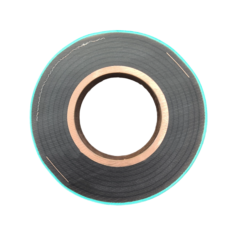
Epoxy resin is widely used in compact busbar systems and cast insulation. Vacuum casting can reduce air voids and improve insulation consistency. It also allows the insulating material to conform closely to the conductor geometry, creating a compact integrated component.
Epoxy resin cast busbars are suitable for installations where space, fire performance, mechanical protection, and low maintenance are important. The resin formulation and curing process must be carefully controlled. Mixing ratio, vacuum level, mold temperature, curing time, and post-curing conditions all affect final performance.
5. Comparison with Conventional Rectangular Busbar Arrangements
Rectangular busbars remain widely used because they are familiar, accessible, and available in many copper and aluminum grades. However, their support requirements can become significant as current, span length, and short-circuit level increase.
A tubular busbar offers a circular geometry that distributes stress more evenly. It can provide higher stiffness for its material quantity and may support longer spans. The enclosed or cast configuration can also improve protection against accidental contact, contamination, and moisture.
In a rectangular busbar system, several parallel bars may be required for high current. These bars need careful spacing and multiple supports to resist electrodynamic movement. The number of insulators, spacers, and fittings may increase accordingly.
A tubular system can combine high current capacity, structural strength, and insulation in a more integrated form. This can reduce the number of discrete components and create a more orderly layout. The advantages become particularly clear in high-current substations, power plants, wind turbine transformer connections, and industrial distribution systems.
However, tubular busbars are not automatically superior for every installation. Project requirements, current rating, fault level, installation space, cost, connection method, and future expansion must be evaluated. A professional manufacturer should provide a technical comparison rather than recommending a single format for every application.
6. Manufacturing Process and Quality Control
The performance of a post insulator or integrated busbar depends strongly on manufacturing quality. Electrical products may appear simple externally while containing demanding internal requirements. Dimensional accuracy, material consistency, bonding quality, surface condition, and electrical integrity must be controlled throughout production.
Engineering and Product Design
The process begins with application engineering. Engineers review voltage level, current rating, short-circuit current, support span, installation orientation, mechanical loading, pollution class, altitude, ambient temperature, seismic requirements, and connection dimensions.
Three-dimensional modeling and technical drawings are used to define the conductor geometry, insulation thickness, mounting holes, fitting arrangement, support locations, and interface dimensions. For customized products, the manufacturer can adapt the post insulator or busbar assembly to the customer’s equipment layout.
Design verification may include electrical field analysis, thermal calculations, short-circuit force calculations, mechanical stress analysis, and seismic evaluation. These analyses help identify high-stress areas and improve the design before production begins.
Conductor Preparation
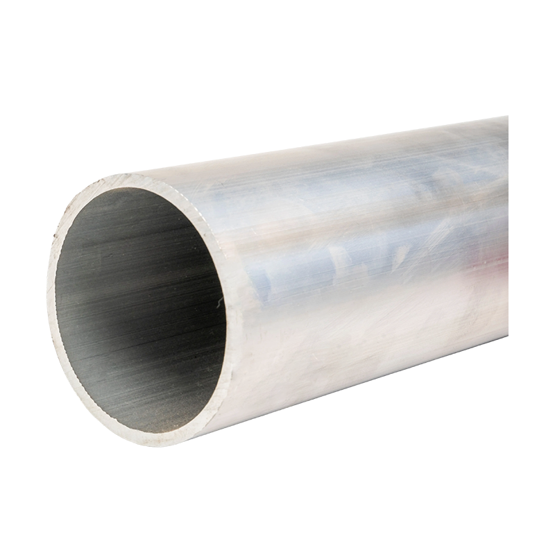
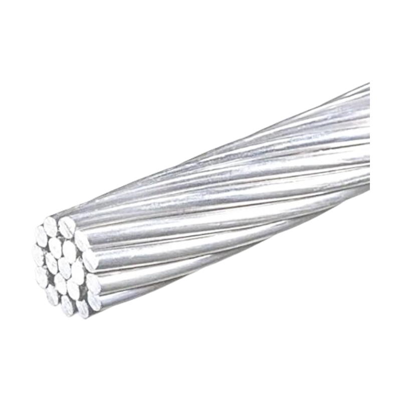
For aluminum or copper tubular busbars, the conductor is cut, formed, machined, and prepared according to the approved drawing. CNC machining equipment can produce accurate connection surfaces, drilling patterns, grooves, and terminal interfaces.
Surface preparation is important because oxidation, oil, dust, and burrs can affect electrical connection quality or bonding with insulating materials. Cleaning and inspection procedures are applied before casting, coating, assembly, or terminal installation.
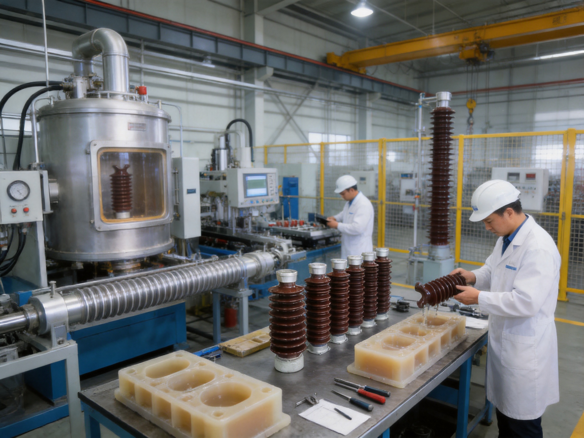
Vacuum Casting and Resin Processing
For epoxy resin cast busbars and cast insulating components, the conductor and mold are prepared before resin filling. Vacuum processing helps remove trapped air and moisture from the mold and resin system. This reduces the risk of internal voids that could lead to partial discharge, local heating, or dielectric failure.
The resin is mixed according to a controlled formulation. Temperature, viscosity, vacuum level, filling speed, curing temperature, and curing time are monitored. After casting, the component may undergo post-curing to achieve the required mechanical and electrical properties.
Automated or semi-automated equipment improves repeatability. Consistent process parameters help ensure that different production batches maintain similar insulation thickness, dimensional accuracy, and material performance.
Metal Fittings and Mechanical Assembly
Metal end fittings and support components must be manufactured with accurate dimensions and appropriate surface treatment. The connection between the fitting and insulating body is a critical area because it transfers mechanical loads and must also prevent moisture ingress.
Assembly procedures control torque, alignment, adhesive application, sealing, and curing. Incorrect tightening can create excessive local stress in porcelain, polymer, or epoxy components. A professional production line uses documented assembly instructions and inspection records to reduce this risk.
Inspection and Testing
Each product undergoes standardized inspection according to its design and application. Dimensional inspection verifies length, diameter, hole position, mounting height, and interface accuracy. Visual inspection checks for cracks, surface defects, voids, resin overflow, contamination, and incorrect assembly.
Electrical tests may include insulation resistance, power-frequency withstand voltage, impulse withstand voltage, partial discharge measurement, and dielectric loss testing where applicable. Mechanical tests may include bending load, tensile load, compression load, torque, vibration, or short-circuit simulation.
Routine tests are supported by type tests and design verification. Cooperation with independent third-party testing institutions can provide additional confirmation of performance and help customers satisfy project approval requirements.
| Quality Control Stage | Key Inspection Items | Purpose |
|---|---|---|
| Incoming material inspection | Resin, metal, porcelain, polymer, fittings, and conductor materials | Confirm material identity and consistency |
| Machining inspection | Dimensions, surface finish, drilling, and terminal geometry | Ensure installation compatibility |
| Casting process inspection | Vacuum level, temperature, filling, curing, and resin condition | Reduce voids and improve insulation integrity |
| Assembly inspection | Alignment, torque, sealing, bonding, and connection quality | Ensure mechanical and electrical reliability |
| Routine testing | Insulation, withstand voltage, appearance, and mechanical checks | Verify conformity before delivery |
| Final documentation | Test records, inspection reports, drawings, and traceability data | Support project acceptance and future maintenance |
7. Why Choose an Integrated Manufacturing Partner?
Buying a post insulator from an integrated busbar manufacturer offers advantages over purchasing isolated components from a general hardware supplier. The manufacturer can evaluate the insulator together with the conductor, support bracket, terminal, insulation system, and complete electrical application.
This integrated capability helps prevent interface problems. A post insulator may have adequate rated voltage but still be unsuitable if the mounting height, bending load, creepage distance, or connection pattern does not match the busbar system. A busbar manufacturer understands these relationships and can develop a more suitable solution.
Jiangsu Wopeng Power Technology Co., Ltd. was founded in 2018 as a specialized high-tech enterprise focused on high- and low-voltage busbar systems. The company combines product development, engineering design, manufacturing, assembly, testing, and OEM service.
Its product portfolio covers 35 kV epoxy resin vacuum-cast tubular busbars, low-voltage cast resin busways, copper and aluminum tubular busbars, wind power tubular busbars, compact busbar systems, and sliding contact line power supply systems. This broad product range enables the company to support different current levels, voltage classes, installation environments, and equipment interfaces.
The company operates production lines equipped with vacuum casting systems, CNC machining equipment, and automated assembly technologies. These resources are important for producing repeatable insulation systems and accurately machined conductor connections.
Wopeng has established a team of engineers, technical specialists, and production professionals with experience in power equipment technology. The company’s quality management system includes high-voltage tests, insulation tests, mechanical verification, routine inspections, and cooperation with third-party testing organizations.
Its products operate across more than 17 provinces and multiple industrial sectors. Applications include power generation, substations, wind energy, industrial manufacturing, rail transit, and large commercial facilities. This application experience helps the company understand the practical requirements of installation, commissioning, operation, and maintenance.
8. Product Advantages over Conventional Alternatives
Space Efficiency
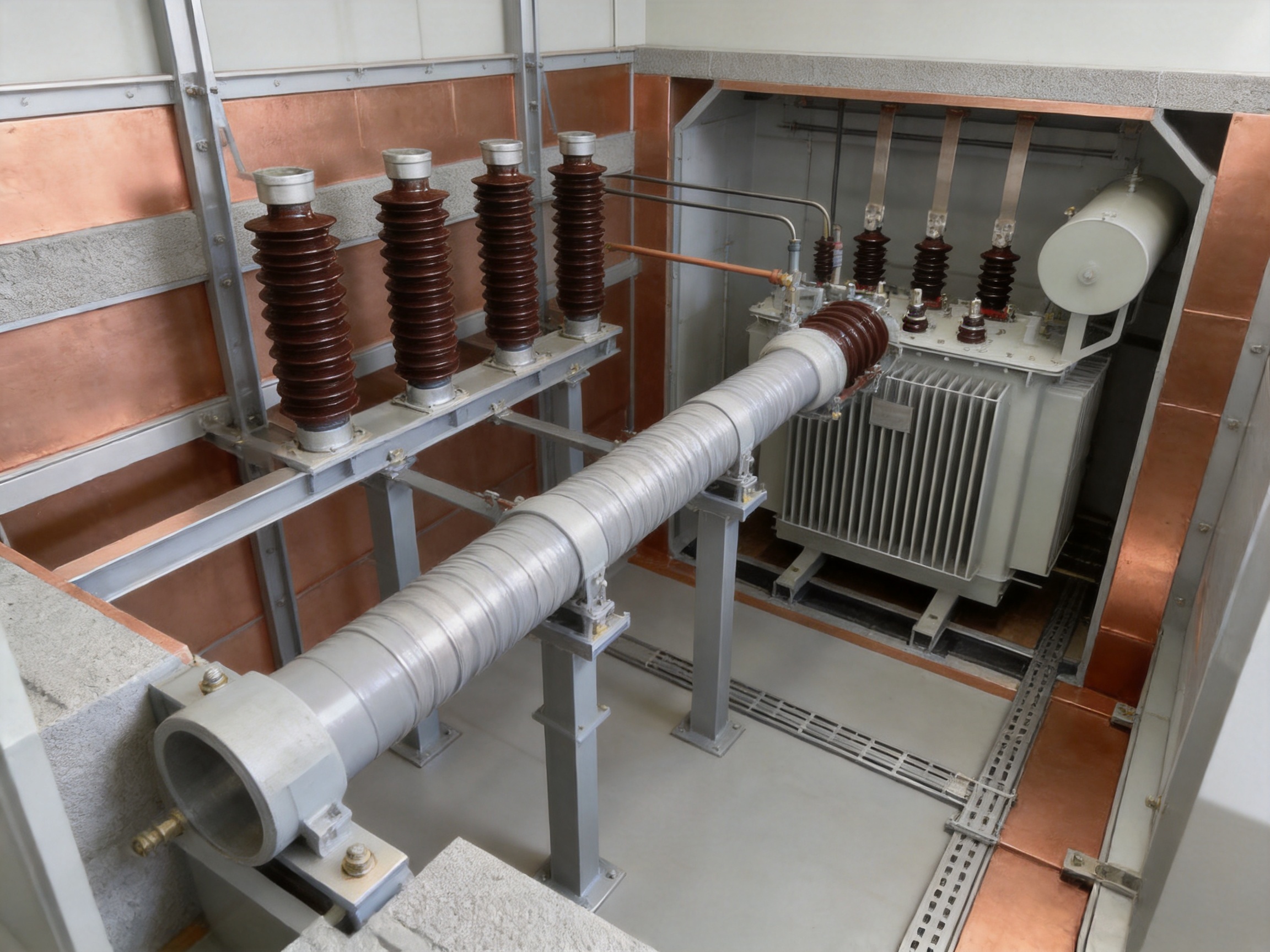
Integrated tubular busbar systems can provide a more compact arrangement than multiple rectangular conductors and separate insulating supports. This is valuable in indoor substations, transformer rooms, switchgear areas, and industrial facilities where equipment space is restricted.
A compact design may also shorten the distance between equipment terminals. Direct connection to high-voltage rooms, current-limiting reactors, and 10 kV switchgear cabinets can reduce transition components and simplify routing.
Lower Component Count
Structural optimization can reduce the number of post insulators, brackets, fittings, wall bushings, and support foundations. Fewer components can reduce procurement complexity and shorten assembly time.
A lower component count also reduces the number of individual interfaces that require inspection. This may improve reliability by reducing the possibility of loose fasteners, incorrect alignment, contamination accumulation, or installation error.
Higher Span Capability
The strong tubular conductor and appropriate support arrangement can allow longer spans than conventional rectangular busbars under comparable conditions. Longer spans may improve access below the busbar and reduce the need for structural steel.
Span capability depends on conductor dimensions, material, temperature, fault current, support spacing, bracket type, and allowable deflection. The manufacturer should provide engineering calculations for each project rather than applying a general span value without verification.
Improved Environmental Protection
Cast or fully insulated busbars protect the conductor from direct contact, dust, moisture, and accidental foreign objects. This can be advantageous in industrial locations, humid facilities, transport infrastructure, and areas with limited access control.
The insulation system also supports cleaner electrical clearances. By controlling the insulating layer and external surface, the design can reduce the exposure of energized metal surfaces and help maintain stable performance over time.
OEM Customization
Different projects require different conductor sizes, terminal arrangements, support positions, insulation thicknesses, creepage distances, and enclosure interfaces. A custom manufacturer can adjust the product to suit the customer’s equipment layout.
Customized solutions may include special lengths, non-standard connection plates, vertical or horizontal arrangements, expansion sections, transition assemblies, seismic support improvements, and compatibility with existing switchgear or transformer terminals.
9. Application Areas
Substations
Substations use post insulators and tubular busbars to connect transformers, circuit breakers, disconnectors, reactors, instrument transformers, and outgoing feeders. High mechanical strength and reliable insulation are especially important because fault currents can be substantial.
Outdoor substations may require high creepage distance, weather-resistant materials, and pollution-resistant surface designs. Indoor substations may prioritize compactness, fire performance, low maintenance, and easy connection to switchgear.
Power Generation Plants
Power plants require reliable high-current connections between generators, step-up transformers, auxiliary transformers, switchgear, and distribution equipment. Tubular busbars can provide robust connections in areas where current levels and short-circuit forces are high.
Post insulators support conductors at equipment transitions and help maintain electrical clearances around generator terminals and high-current assemblies.
Wind Power Facilities
Wind turbines and wind power collection systems require compact, mechanically stable, and environmentally resistant electrical connections. Tubular busbars can be adapted to the limited internal space of wind turbine towers and nacelles.
Vibration resistance is particularly important in wind power applications. The support design must tolerate continuous mechanical vibration, temperature changes, and movement while maintaining insulation integrity.
Industrial Manufacturing Facilities
Steel mills, chemical plants, automotive factories, and other industrial facilities often use high-current distribution systems for furnaces, motors, welding equipment, drives, and process machinery. Busbar systems must withstand high load currents and demanding operating conditions.
Cast or insulated tubular busbars can help improve operator safety and reduce contamination-related maintenance in industrial environments where conductive dust, oil mist, humidity, or chemical pollutants may be present.
Rail Transit and Commercial Infrastructure
Rail transit systems and large commercial buildings require reliable power distribution with limited maintenance access. Compact busbar systems can support efficient routing in substations, equipment rooms, tunnels, stations, and high-rise buildings.
Sliding contact line systems may be used for specialized power supply applications, while insulated busbars support fixed distribution connections between major electrical units.
10. Installation Recommendations
Before installation, verify the product model, drawing revision, rated voltage, current rating, support arrangement, and connection dimensions. Confirm that the delivered components have not been damaged during transportation.
Storage areas should be clean, dry, and protected from impact. Polymer, epoxy, and metal components should be protected from prolonged exposure to direct sunlight or chemicals when specified by the manufacturer. Porcelain components should be handled carefully to avoid impact and hidden cracking.
During installation, ensure that supports are correctly positioned and level. The mounting surface must be clean and free from burrs. Bolts should be tightened using the specified torque. Excessive force can damage insulating bodies or distort fittings, while insufficient force can lead to vibration and overheating.
Maintain the specified support spacing. For exposed tubular busbar systems, dedicated brackets should be arranged according to the approved design, with spacing of at least 275 mm where applicable. Fixed brackets are required for long spans from 6 to 13 meters according to the system design.
Provide sliding supports or expansion provisions where thermal movement is expected. Do not lock every support point unless the design specifically requires it. Thermal stress can otherwise be transferred to equipment bushings and connection terminals.
After assembly, inspect phase spacing, ground clearance, terminal alignment, fastener torque, grounding continuity, and surface condition. Perform the required electrical tests before energization. Where partial discharge testing or specialized commissioning tests are specified, they should be completed by qualified personnel.
11. Maintenance and Service Life
High-quality post insulators can provide a service life of approximately 20 to 40 years under normal indoor or outdoor conditions, provided that the product is correctly selected, installed, and maintained. Actual service life depends on voltage stress, pollution, temperature, mechanical loading, ultraviolet exposure, chemical conditions, and maintenance quality.
Routine inspections should identify cracks, chips, surface contamination, discoloration, corrosion, loose fittings, abnormal vibration, and signs of overheating. Polymer components should be checked for housing damage, erosion, chalking, tracking, or loss of hydrophobicity. Epoxy cast systems should be checked for visible cracking, separation, or signs of partial discharge.
Thermal imaging can help identify loose or high-resistance electrical connections. Insulation resistance and withstand tests may be performed during planned maintenance according to the equipment maintenance program. If abnormal noise, smell, discharge marks, or repeated protective trips occur, the equipment should be de-energized and inspected by qualified technicians.
In polluted environments, cleaning requirements depend on the material and system design. Silicone rubber may reduce contamination adhesion, but heavy pollution can still affect performance. Cleaning should follow the manufacturer’s recommendations to avoid damaging the insulating surface.
12. Frequently Asked Questions
Q1: What is the main purpose of a post insulator?
A post insulator supports an energized conductor or busbar while electrically isolating it from grounded structures and other phases. It also helps maintain fixed clearances and resist mechanical forces.
Q2: Can tubular busbars eliminate post insulators completely?
In some optimized insulated tubular busbar systems, the number of traditional post insulators can be significantly reduced or certain support functions can be integrated into the busbar and bracket structure. However, post insulators may still be required at equipment terminals, transitions, outdoor supports, and locations requiring additional electrical or mechanical separation.
Q3: Which material is best for a post insulator?
There is no single best material for every application. Porcelain provides proven outdoor performance and high strength. Silicone rubber offers low weight and hydrophobicity. Epoxy resin is suitable for compact cast busbars and integrated insulation. Selection should consider voltage, pollution, mechanical loading, temperature, altitude, and installation environment.
Q4: What voltage levels can post insulators support?
Post insulators are available for applications ranging from low voltage to high voltage. Some product families cover voltage levels up to 550 kV, but the actual rating depends on the design, material, insulation coordination, creepage distance, and applicable standards.
Q5: What short-circuit current can a tubular busbar withstand?
Short-circuit capability depends on conductor size, material, support spacing, fault duration, installation arrangement, and mechanical design. Under a specified 50 kA short-circuit condition, a Φ100 × 6 mm tubular busbar can achieve a suspended span of up to 9 meters or a supported span of up to 13 meters in an appropriate design.
Q6: Are post insulators suitable for polluted areas?
Yes, provided that the creepage distance, material, shed profile, and pollution classification are correctly selected. Silicone rubber and optimized porcelain designs can provide strong pollution performance. Severe pollution may require additional creepage length or creepage extenders.
Q7: Can the products be customized?
Customized options may include dimensions, mounting holes, terminal plates, conductor sizes, support locations, insulation thickness, creepage distance, expansion sections, and equipment interfaces. Technical drawings and application data should be provided before production.
Q8: What tests should be requested before delivery?
Depending on the project, customers may request dimensional inspection, insulation resistance testing, power-frequency withstand testing, impulse testing, partial discharge testing, mechanical load verification, material certificates, routine inspection records, and third-party type test reports.
Q9: How should a post insulator be maintained?
Maintenance should include visual inspection, cleaning where required, checking of bolts and fittings, confirmation of grounding continuity, thermal inspection of connections, and electrical testing during planned outages. Any crack, tracking mark, abnormal heating, or mechanical looseness should be investigated immediately.
Q10: Why purchase a post insulator from a busbar manufacturer?
A busbar manufacturer can evaluate the post insulator together with the conductor, support bracket, terminal, insulation system, and installation environment. This reduces interface problems and supports a more reliable complete system than selecting components independently.
13. Selecting the Right Supplier
A reliable supplier should have experience with the required voltage class, current rating, material system, and application environment. Customers should review the manufacturer’s technical capability, production equipment, quality control procedures, inspection records, engineering support, and ability to provide customized drawings.
It is also important to confirm whether the supplier can support the complete project lifecycle. Design assistance, sample production, factory testing, packaging, installation guidance, commissioning support, and after-sales service can all affect project success.
For high-voltage and high-current systems, the supplier should provide clear information about insulation coordination, short-circuit withstand capability, seismic design, pollution performance, altitude suitability, creepage distance, mechanical load, and thermal behavior.
Documentation is another important factor. Technical drawings, product specifications, test reports, material information, installation instructions, and maintenance recommendations help the customer complete approval, installation, and future inspection.
Jiangsu Wopeng Power Technology Co., Ltd. provides customized busbar and electrical system solutions supported by engineering design and manufacturing resources. Its facilities include vacuum casting systems, CNC machining equipment, and automated assembly technologies. Its product experience extends from low-voltage busways to 35 kV epoxy resin tubular busbars and specialized tubular busbars for wind power applications.
By combining post insulator technology with tubular busbar engineering, the company can address both component-level and system-level requirements. This approach supports safer layouts, efficient installation, strong mechanical performance, and long-term electrical reliability.
14. Conclusion
Post insulators remain important components in medium- and high-voltage electrical systems. Their role includes supporting conductors, maintaining electrical isolation, resisting short-circuit forces, controlling clearances, and contributing to the structural stability of substations, switchgear, industrial plants, and renewable energy facilities.
Modern insulated tubular busbar systems improve on conventional arrangements by integrating conductor strength, insulation, and mechanical support. In suitable applications, they can reduce the number of post insulators, fittings, wall bushings, and structural foundations. Their high allowable stress, long support spans, strong seismic performance, and environmental adaptability provide practical advantages over conventional rectangular busbar solutions.
The effectiveness of the system depends on professional design and manufacturing. Vacuum casting, CNC machining, automated assembly, controlled material processing, and standardized electrical and mechanical testing help ensure consistent product quality. Customized engineering also allows the post insulator and busbar system to match the customer’s voltage level, current rating, support structure, pollution environment, altitude, and equipment interface.
With experience in high- and low-voltage busbar systems, Jiangsu Wopeng Power Technology Co., Ltd. provides integrated solutions for substations, power plants, wind energy, industrial manufacturing, rail transit, and large commercial facilities. Its combination of engineering capability, production technology, testing procedures, and OEM service makes it a suitable partner for projects requiring reliable post insulators and advanced tubular busbar systems.
References
1. IEC 60168, Tests on Indoor and Outdoor Post Insulators of Ceramic Material or Glass for Systems with Nominal Voltages Greater Than 1,000 V.
2. IEC 62271 Series, High-Voltage Switchgear and Controlgear.
3. IEC 60071 Series, Insulation Coordination.
4. IEC 60815 Series, Selection and Dimensioning of High-Voltage Insulators Intended for Use in Polluted Conditions.
5. IEC 60076 Series, Power Transformers and Associated Connection Requirements.
6. IEEE standards and technical guidance for substation bus design, short-circuit mechanical forces, seismic qualification, and electrical insulation coordination.
7. Manufacturer technical documentation for insulated tubular busbar systems, epoxy resin cast busbars, aluminum tubular busbars, and post insulator assemblies.
8. Engineering practices for high-voltage substation layout, busbar support design, pollution performance, and maintenance planning.
Product: Post Insulator




-
 +86-180 3625 3000
-
 admin@wpbusbar.com
-
 No. 8, Yanjin Road, Chengxi Industrial Park, Shanyang Town, Baoying County, Yangzhou City, Jiangsu Province, China
Copyright © Jiangsu Wopeng Power Technology Co., Ltd.
All Rights Reserved.
 Custom Insulated Bus Bar Manufacturer
Tubular Busbar System Factory