

 EN

 English
 русский
 Français
 Español
 عربى
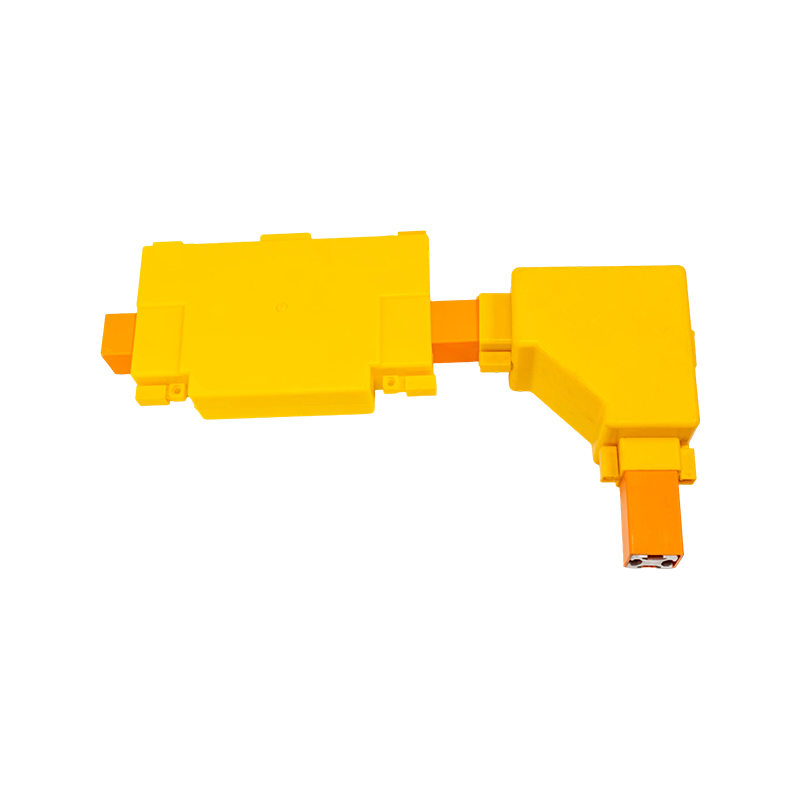

Bus-Bar Supports for Reliable Medium- and Low-Voltage Power Distribution Systems
Content
- 1 1. The Role of Bus-Bar Supports in Electrical Systems
- 2 2. Product Structure and Main Hardware Types
- 3 3. Materials and Surface Treatment
- 4 4. Mechanical Performance and Short-Circuit Withstand
- 5 5. Electrical Performance and Insulation Reliability
- 6 6. Environmental Adaptability and Service Life
- 7 7. Advantages Compared with Ordinary Support Hardware
- 8 8. Advanced Manufacturing Capabilities
- 9 9. Applications in Power Distribution and Infrastructure
- 10 10. Selection Guide for Bus-Bar Supports
- 11 11. Installation Recommendations
- 12 12. Maintenance and Inspection
- 13 13. Customization and OEM Support
- 14 14. Company Manufacturing Strength and Product Portfolio
- 15 15. Frequently Asked Questions
- 15.1 Q1: What are Bus-bar Supports used for?
- 15.2 Q2: What tubular busbar diameters are supported by Type MGG fixed hardware?
- 15.3 Q3: What is the function of Type MGF end caps?
- 15.4 Q4: What is the advantage of the damping end-cap type?
- 15.5 Q5: What steel strand diameters are suitable for the tension clamps?
- 15.6 Q6: Why is hot-dip galvanized steel used for the hardware?
- 15.7 Q7: What is the difference between standard and reinforced fixed hardware?
- 15.8 Q8: What insulating materials are commonly used in bus-bar supports?
- 15.9 Q9: Are these support systems suitable for medium-voltage applications?
- 15.10 Q10: How should customers select a support for a new project?
- 15.11 Q11: Can support hardware be customized?
- 15.12 Q12: What testing is important for bus-bar supports?
- 15.13 Q13: How can support service life be extended?
- 16 16. Conclusion
- 17 References
- 18 Product: Bus-bar Supports (Fixed Support Type)
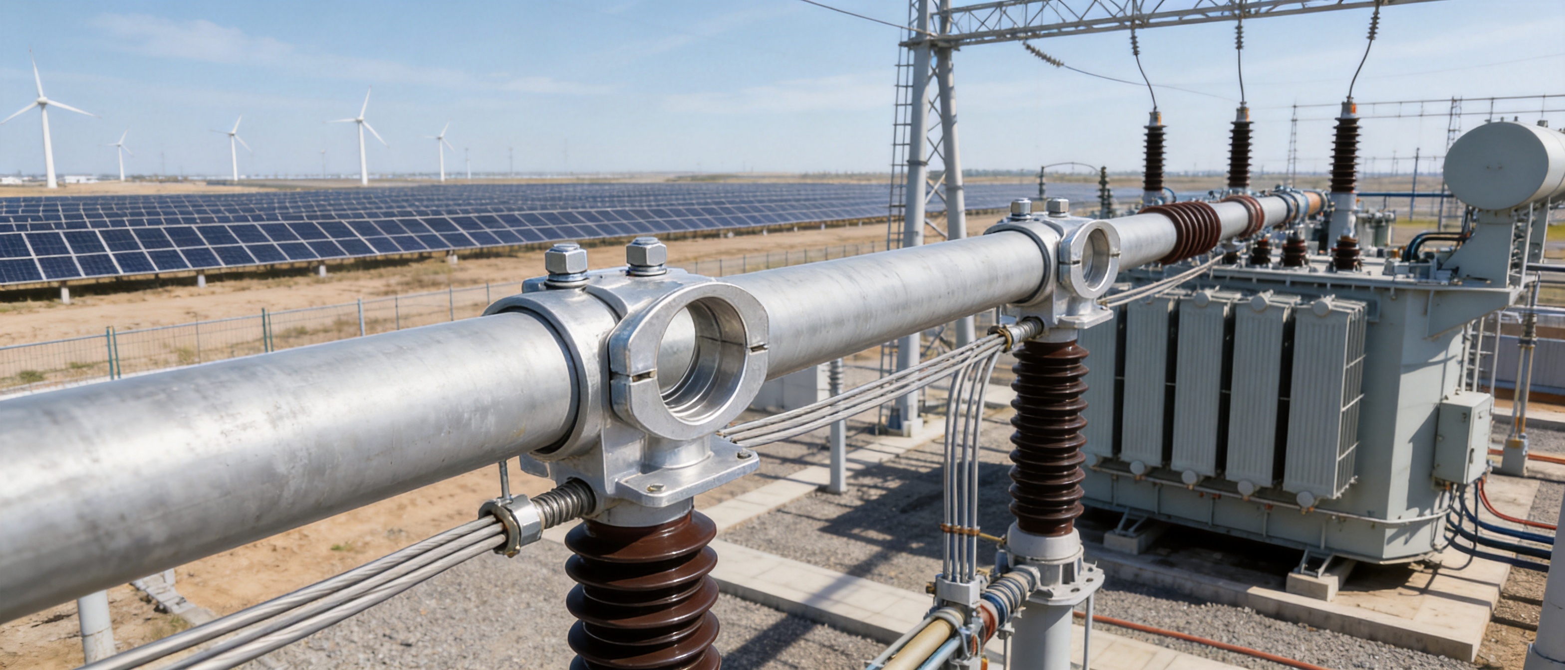
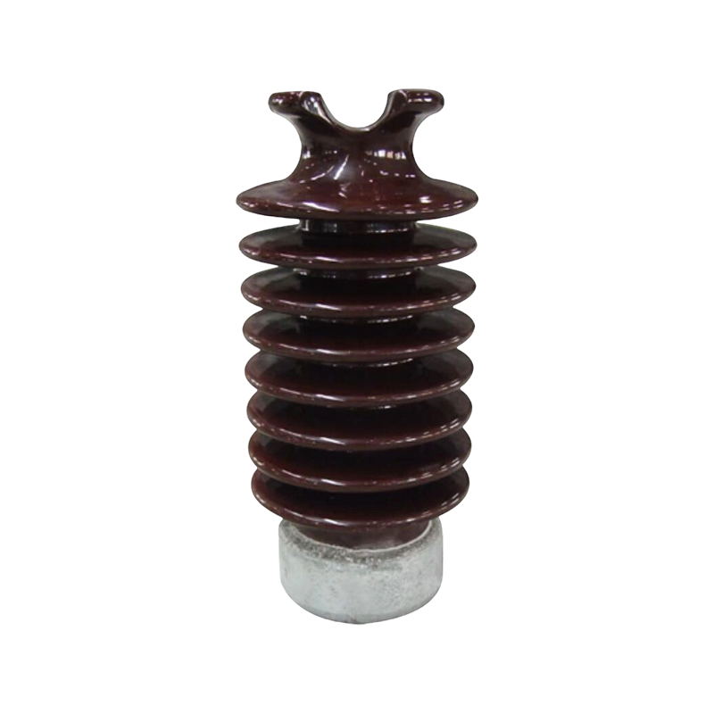
Bus-bar supports are essential mechanical and insulating components used to position, secure, and stabilize bus bars in electrical distribution equipment. Although they are compact compared with the conductors and enclosures they support, their performance directly affects system safety, insulation coordination, short-circuit withstand capability, service life, and maintenance requirements. A properly engineered support system keeps bus bars accurately aligned, maintains designed clearances, limits movement under electrodynamic forces, and helps prevent phase-to-phase or phase-to-ground faults.
Modern power distribution systems require more than a simple mounting block. They must operate safely under continuous current, thermal cycling, vibration, humidity, corrosive atmospheres, and sudden short-circuit forces. For this reason, high-quality Bus-bar Supports (Fixed Support Type) are engineered as part of the complete busbar system rather than treated as generic accessories. Material selection, dimensional accuracy, mechanical design, surface treatment, manufacturing control, and inspection all contribute to the final performance of the installation.
Jiangsu Wopeng Power Technology Co., Ltd. provides busbar support hardware and related tubular busbar accessories for high- and low-voltage power transmission applications. Its product range includes Type MGG fixed hardware for tubular busbars, Type MGF end caps, tension clamps for steel strands, and supporting steel-cored aluminum strands. These products are developed for substations, switchgear, distribution cabinets, transformer stations, renewable energy facilities, industrial plants, rail transit systems, and other projects requiring dependable electrical infrastructure.
1. The Role of Bus-Bar Supports in Electrical Systems
A bus bar carries and distributes electrical current between incoming feeders, outgoing circuits, transformers, switchgear, and other power equipment. Because bus bars often carry high current, they may be manufactured from copper or aluminum and installed in parallel arrangements. Their size, weight, operating temperature, and electromagnetic forces can be considerable. Bus-bar supports hold these conductors in their designed positions and transfer mechanical loads safely to the enclosure or supporting structure.
The primary role of a fixed support is to prevent unwanted movement. During normal operation, a bus bar is exposed to its own weight, thermal expansion, vibration, and forces caused by connected equipment. During a short circuit, the current generates a strong magnetic field. When large currents flow through conductors positioned close to one another, the resulting electrodynamic force can push or pull the bus bars with significant intensity. If the supports are too weak, poorly spaced, or incorrectly installed, the conductors may move enough to damage insulation, loosen connections, or create a flashover path.
Bus-bar supports also preserve electrical clearances. The distance between phases and between live conductors and grounded metalwork must remain within the design requirements of the system. A support with stable insulation and accurate dimensions helps maintain these distances during normal operation and fault conditions. In medium-voltage installations, this function is particularly important because inadequate clearance or surface contamination can contribute to partial discharge, tracking, or insulation breakdown.
In addition to mechanical fixation and insulation, supports assist with orderly assembly. A standardized support design enables installers to position conductors consistently, simplify inspection, and reduce the risk of assembly errors. When supports are compatible with a broad range of tubular busbar diameters, the same hardware platform can be adapted to multiple project configurations, reducing procurement complexity and improving replacement convenience.
Core Functions of Fixed Bus-Bar Supports
Fixed Bus-bar Supports are generally designed to provide several functions at the same time:
Electrical insulation: The support separates energized conductors from one another and from grounded structures.
Mechanical fixation: The support holds the bus bar in a defined position and transfers loads to the supporting frame.
Short-circuit resistance: The support withstands the electrodynamic forces generated during fault conditions.
Vibration control: The support reduces conductor movement caused by machinery, wind, transportation, or switching events.
Thermal stability: The support maintains its shape and insulation properties across the expected operating temperature range.
Installation guidance: The support provides a repeatable mounting reference for accurate system assembly.
Environmental protection: Suitable materials and finishes help maintain performance in humid, polluted, salty, or industrial atmospheres.
These functions must be balanced. A support with excellent insulation but inadequate mechanical strength is unsuitable for a high-current installation. Similarly, a mechanically strong component that has poor dimensional stability or insufficient surface quality may not provide dependable long-term insulation. The most reliable products are therefore developed through integrated electrical, mechanical, thermal, and environmental design.
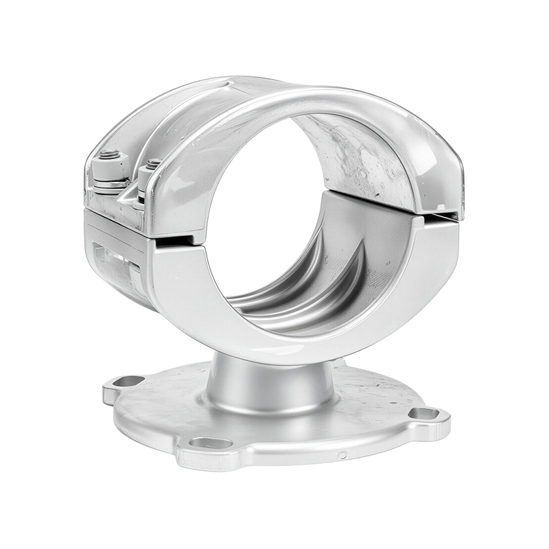
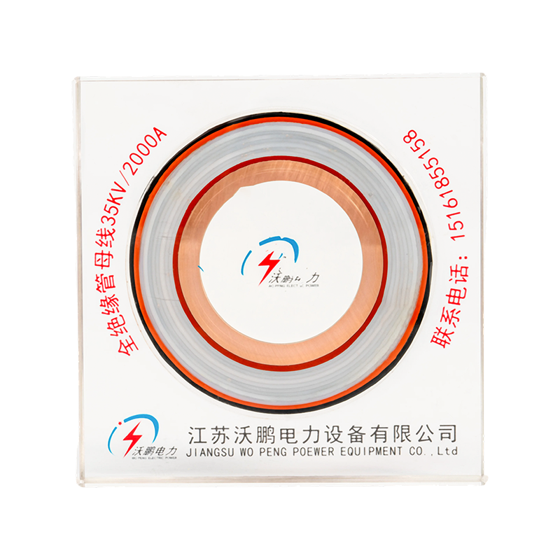
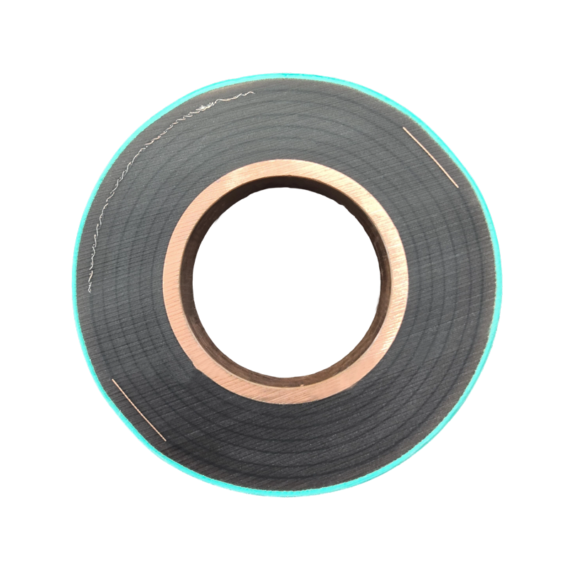
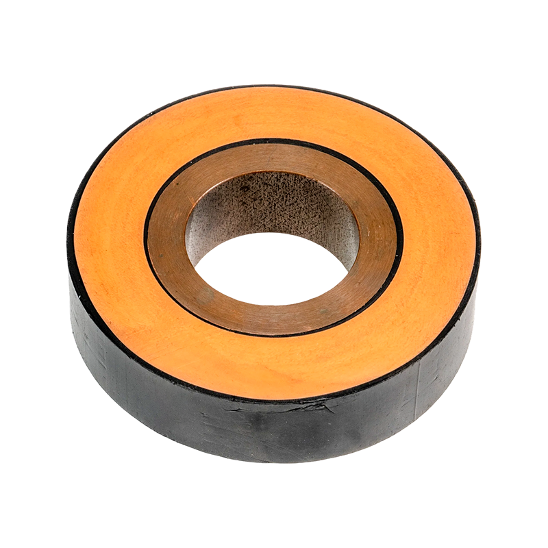
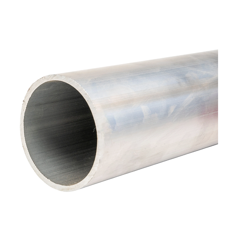
Bus-bar Supports (Fixed Support Type)
2. Product Structure and Main Hardware Types
The fixed support hardware supplied for tubular busbar applications is designed around the geometry and operating requirements of the conductor. Different parts of the system perform different functions, and the complete assembly may include fixed supports, end caps, clamps, connecting elements, and supporting conductors.
Type MGG Fixed Hardware
Type MGG fixed hardware is used to secure tubular busbars and maintain their position along the support structure. The product is compatible with tubular busbar outer diameters from Φ50 mm to Φ180 mm, allowing it to serve a broad range of conductor sizes and project configurations. Standard and reinforced models are available to accommodate different mechanical requirements.
The use of hot-dip galvanized steel components provides a strong and durable mechanical foundation. The galvanized surface helps protect the steel from atmospheric corrosion, while the structural design distributes clamping forces around the tubular conductor. Proper force distribution is important because excessive local pressure may deform a thin-walled tube, while insufficient pressure may allow movement during vibration or fault conditions.
Type MGG hardware is suitable for installations where the tubular busbar must remain firmly fixed over long service periods. The availability of reinforced versions provides a practical solution for projects with higher short-circuit forces, longer support spans, increased conductor weight, or greater environmental exposure.
Type MGF End Caps
Type MGF end caps are used to seal the ends of tubular busbars. They are offered in standard, damping, and terminal-ball types, with compatibility covering inner and outer diameter combinations from Φ50/45 mm to Φ250/230 mm. This range supports a variety of tubular busbar dimensions and termination arrangements.
End caps serve both mechanical and protective functions. They help close the tube, reduce the entry of dust and moisture, and provide a controlled termination profile. A properly designed end cap can also reduce the risk of sharp exposed edges and improve the visual and operational quality of the installation.
The damping type is equipped with LGJ series damping wires. These wires help improve resistance to vibration and seismic movement, making the design suitable for installations in areas where mechanical oscillation, wind-induced movement, or earthquake loads require additional control. The damping options cover LGJ-240 to LGJ-630 damping wires, allowing the configuration to be matched to the electrical and mechanical requirements of the project.
Tension Clamps for Steel Strands
Tension clamps are used to fix and transfer the tension of steel strands. The product range includes integral forged types and universal design types. These configurations allow customers to select a solution based on the required installation method, conductor arrangement, mechanical load, and maintenance preference.
The clamps are compatible with steel strand diameters from Φ7.8 mm to Φ16.0 mm. Grip strength ranges from 45 kN to 187 kN, providing options for different load conditions. Integral forged designs offer a robust, compact construction, while universal designs provide flexibility for broader application requirements.
Reliable tension clamps must maintain their grip without damaging the strand. The contact geometry, surface finish, material strength, and tightening method all influence performance. The use of hot-dip galvanized steel components helps protect the clamps from corrosion while maintaining the mechanical integrity required for overhead and structural applications.
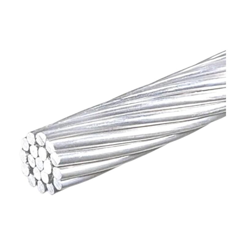
Supporting Steel-Cored Aluminum Strands
The supporting steel-cored aluminum strand products comply with the GB1179-83 standard. Nominal cross-sections cover 10/2 mm² to 240/30 mm². Standardized parameters include calculated cross-section, outer diameter, direct-current resistance, calculated tensile strength, and calculated weight.
Steel-cored aluminum strands combine the conductivity and relatively low weight of aluminum with the tensile strength of a steel core. They are used in power transmission and distribution applications where mechanical span capability and electrical performance must be balanced. Accurate dimensional and electrical data help engineers select the appropriate strand for the current rating, span, tension, and environmental conditions of a project.
3. Materials and Surface Treatment
Material selection is one of the most important differences between ordinary support hardware and professional-grade busbar accessories. The material must withstand mechanical stress, temperature changes, humidity, contaminants, and long-term exposure to the installation environment. It must also maintain stable dimensions so that clearances and clamping forces do not change excessively over time.
Hot-Dip Galvanized Steel Components
Hot-dip galvanized steel is used for the mechanical hardware because it combines strength, toughness, availability, and corrosion protection. During hot-dip galvanizing, the prepared steel component is immersed in molten zinc. The resulting zinc coating forms a protective barrier and provides sacrificial protection when the surface is exposed to moisture or minor damage.
The specified zinc coating thickness is at least 85 μm. This level of coating provides a substantial protective layer for outdoor and industrial use. Compared with uncoated or lightly electroplated steel, hot-dip galvanized components generally offer improved resistance to atmospheric corrosion and better durability in demanding service conditions.
For high-reliability applications, corrosion protection is not only a matter of appearance. Corrosion can reduce cross-sectional area, weaken threaded connections, increase contact resistance, and make maintenance difficult. It can also create rough or contaminated surfaces near energized equipment. A robust galvanized finish helps reduce these risks and supports consistent service performance.
Composite Insulating Materials
Bus-bar support systems for switchgear and distribution equipment commonly use high-performance insulating composites such as DMC or SMC. These materials provide electrical insulation, mechanical strength, dimensional stability, flame resistance, and resistance to environmental degradation.
DMC, or dough molding compound, is a thermoset composite material containing resin, reinforcing fibers, fillers, and additives. It can be molded into complex shapes and offers a useful combination of insulation and mechanical strength. SMC, or sheet molding compound, is also a fiber-reinforced thermoset composite and can provide very high mechanical strength and stable performance in larger or more demanding components.
The material comparison below illustrates typical characteristics used when selecting a support material. Actual performance depends on formulation, molding quality, geometry, testing method, and operating conditions.
| Material | Insulation Performance | Mechanical Strength | Typical Temperature Resistance | Common Application Consideration |
|---|---|---|---|---|
| DMC | Excellent | High | -40°C to 180°C | General fixed supports and compact insulation components |
| SMC | Excellent | Very high | -50°C to 200°C | Reinforced supports and heavy-duty electrical assemblies |
| Hot-dip galvanized steel | Requires electrical separation or insulation interface | High | Suitable for broad outdoor service conditions | Clamps, frames, tension hardware, and mechanical fixation |
In a complete assembly, insulating composites and galvanized steel are used together. The composite section provides electrical separation and controlled conductor positioning, while the steel hardware supplies mechanical strength and secure attachment to the structure. This combination is more effective than relying on one material to perform every function.
Manufacturing and Surface Processes
Professional hardware production involves several controlled processes. Die forging can be used to form high-strength steel components with favorable grain flow and improved resistance to mechanical loading. Heat treatment adjusts hardness, strength, and toughness so that the finished component can withstand both continuous loads and sudden impact.
Surface sandblasting removes contaminants and prepares the component for subsequent treatment. Passivation and other protective processes improve surface stability and help reduce corrosion initiation. In addition, controlled dimensional machining ensures that contact surfaces, mounting holes, threads, and interfaces meet the specified tolerances.
For special regions, enhanced anti-corrosion coating solutions can be considered. These may be appropriate for coastal areas, chemical plants, high-humidity regions, or locations where salt, dust, and industrial pollutants are present at elevated levels. The correct solution should be selected according to the actual corrosivity category, installation exposure, and maintenance plan.
4. Mechanical Performance and Short-Circuit Withstand
Short-circuit conditions place exceptional stress on busbars and their supports. When fault current rises rapidly, the magnetic forces between adjacent conductors can be many times greater than the normal operating load. The support system must resist this force without cracking, excessive deflection, conductor displacement, or loss of insulation clearance.
The hardware described for these applications provides grip strength from 45 kN to 187 kN for the relevant tension clamp range. A safety factor of 2.5 is used in the mechanical design approach. This reserve helps account for variations in installation, dynamic loading, material tolerances, and unexpected operating conditions.
Finite element analysis is used to optimize stress distribution in the support structure. Through this method, engineers can identify high-stress areas, improve load paths, adjust radii and wall thicknesses, and reduce unnecessary concentrations of force. A well-optimized structure is not simply heavier; it uses material efficiently while maintaining the strength and stiffness required by the application.
Fatigue performance is also important. Even when a support does not experience a major short circuit, it may be subjected to repeated vibration from equipment operation, switching, transportation, wind, or thermal movement. The stated fatigue life target of 107 vibration cycles reflects the need for long-term structural reliability.
Resonance control is another consideration. If the natural frequency of a support assembly overlaps with a recurring excitation frequency in the system, vibration may become amplified. Controlling resonance frequencies outside the normal operational range helps reduce fatigue damage and loosening. This is especially useful for tubular busbars installed over longer spans or in environments with strong mechanical excitation.
Support spacing must be determined by the busbar design, fault current, conductor weight, enclosure geometry, and applicable standards. A high-strength support cannot compensate for incorrect spacing or inadequate fastening. Engineering calculations and installation instructions should therefore be used together when configuring the system.
5. Electrical Performance and Insulation Reliability
Bus-bar supports operate close to energized conductors, so electrical performance must be considered alongside mechanical strength. The support geometry should preserve creepage and clearance distances, avoid sharp field concentrations, and minimize the possibility of surface tracking or partial discharge.
The design approach considers electrothermal coupling effects. Current flowing through a busbar creates heat, and temperature changes can influence mechanical expansion, contact pressure, and insulation performance. At the same time, the physical arrangement of metal components can affect eddy current losses. Optimizing the support and hardware layout helps limit unnecessary electromagnetic losses while maintaining mechanical stability.
Under short-circuit conditions, electromagnetic force calculations are used to verify that the support structure remains stable. The design must account for the expected current magnitude, conductor spacing, fault duration, support interval, and connection arrangement. The goal is not only to prevent immediate failure but also to keep the busbar aligned and the insulation system intact after the event.
Contact resistance is controlled below 50 μΩ for the applicable hardware interfaces. Low contact resistance helps reduce localized heating and energy loss. Clean contact surfaces, correct tightening torque, suitable interfaces, and consistent manufacturing tolerances are all important for achieving this performance.
Anti-corona design is particularly relevant to medium- and high-voltage applications. Corona and partial discharge can develop when electric fields become concentrated around irregular edges, gaps, or poorly controlled terminations. Smooth contours, appropriate end-cap geometry, adequate insulation distances, and controlled interfaces help reduce the risk of partial discharge in high-voltage environments.
Insulation resistance is another key indicator. The support systems described for distribution applications are designed to maintain high insulation resistance, with the stated target exceeding 1.0 × 10¹² Ω for applicable insulating components. The actual value depends on material, humidity, surface cleanliness, test voltage, temperature, and test method. Regular inspection remains important in environments where dust, moisture, salt, or conductive contamination may accumulate.
Flame Resistance and Safety
Many modern insulating support materials are designed to meet UL94 V-0 flame-retardant requirements. Flame-retardant material helps limit the spread of fire if an abnormal heating event occurs. It does not eliminate the need for proper overcurrent protection, clearances, ventilation, and system maintenance, but it contributes an important layer of passive safety.
Thermoset composite materials also provide dimensional stability under heat. Unlike some ordinary thermoplastics, properly formulated thermosets do not soften in the same way when exposed to elevated temperature. This characteristic is valuable in high-current systems where conductor heating may be significant.
6. Environmental Adaptability and Service Life
Electrical equipment is often installed in conditions that are much more severe than a clean indoor laboratory. Outdoor substations may experience rain, solar radiation, salt spray, temperature changes, wind, and dust. Industrial facilities may expose equipment to oil mist, chemical vapors, conductive particles, and vibration. Reliable bus-bar supports must retain their mechanical and insulating properties throughout these conditions.
The hardware and materials are evaluated through environmental testing that includes 3,000 hours of salt spray testing and 2,000 hours of ultraviolet aging tests. These tests provide information about corrosion resistance, coating stability, surface degradation, discoloration, cracking, and loss of mechanical performance.
The stated operating temperature cycling range is -40°C to 60°C. This range covers many outdoor and industrial applications, including cold winter starts and hot equipment rooms. Repeated temperature changes can cause differential expansion between metals, composite materials, fasteners, and busbars. A well-designed support system limits the resulting stress and preserves the required alignment.
Under humid and hot conditions, insulation resistance remains above 104 MΩ for the applicable components and test conditions. This is important because moisture can reduce surface resistance and increase the possibility of leakage current or tracking. Proper enclosure design, drainage, sealing, and cleaning are also necessary to maintain insulation performance in service.
In corrosive environments classified at C4 level, enhanced coating solutions can extend the life of exposed metallic parts. However, coating selection should be based on the complete installation environment. Coastal salt exposure, chemical plant atmospheres, and heavy industrial pollution may require different protective strategies. Stainless steel fasteners, additional sealing, or periodic inspection may also be appropriate depending on the project.
7. Advantages Compared with Ordinary Support Hardware
Customers comparing bus-bar support suppliers should evaluate more than unit price. A low-cost component may appear economical at purchase but create higher costs through installation difficulty, premature corrosion, loosened connections, insulation failure, or unplanned shutdowns. The advantages of a professionally engineered support system are reflected in reliability over the complete service life.
Broader Dimensional Compatibility
The Type MGG range supports tubular busbar outer diameters from Φ50 mm to Φ180 mm, while Type MGF end caps cover inner and outer diameter combinations from Φ50/45 mm to Φ250/230 mm. This broad compatibility makes it easier to standardize hardware across multiple projects and simplifies the selection of replacement components.
Many generic suppliers focus on a narrow group of common dimensions. When a project uses a nonstandard tube size, customers may need to modify the support on site or order a completely new design. A broader standardized range reduces such risks and supports more efficient project planning.
Higher Mechanical Reserve
Reinforced fixed hardware, forged tension clamps, finite element optimization, and a stated safety factor of 2.5 provide a stronger mechanical foundation than basic stamped or lightly formed alternatives. Higher mechanical reserve is particularly valuable in high-current systems, seismic regions, outdoor substations, and installations with demanding short-circuit requirements.
Improved Corrosion Protection
Hot-dip galvanizing with a zinc coating thickness of at least 85 μm provides more durable corrosion protection than untreated steel or thin decorative plating. Additional sandblasting, passivation, and optional enhanced coatings support use in polluted and humid environments.
Integrated Vibration and Damping Options
The availability of damping-type MGF end caps with LGJ-240 to LGJ-630 damping wires gives engineers an integrated option for vibration and seismic control. Ordinary end closures may provide sealing only, while a damping configuration addresses both termination protection and mechanical movement.
Controlled Electrical Interfaces
Electrical performance is considered through contact resistance control, electromagnetic force analysis, anti-corona geometry, and insulation design. These features help the support hardware operate as part of a coordinated electrical system instead of acting as an isolated mechanical component.
Documented Manufacturing and Testing
Quality depends on repeatability. Standardized manufacturing, inspection records, material control, dimensional verification, mechanical testing, insulation testing, and third-party testing cooperation allow customers to evaluate the product on objective technical evidence. This is a significant advantage over suppliers that provide limited documentation or rely only on visual inspection.
8. Advanced Manufacturing Capabilities
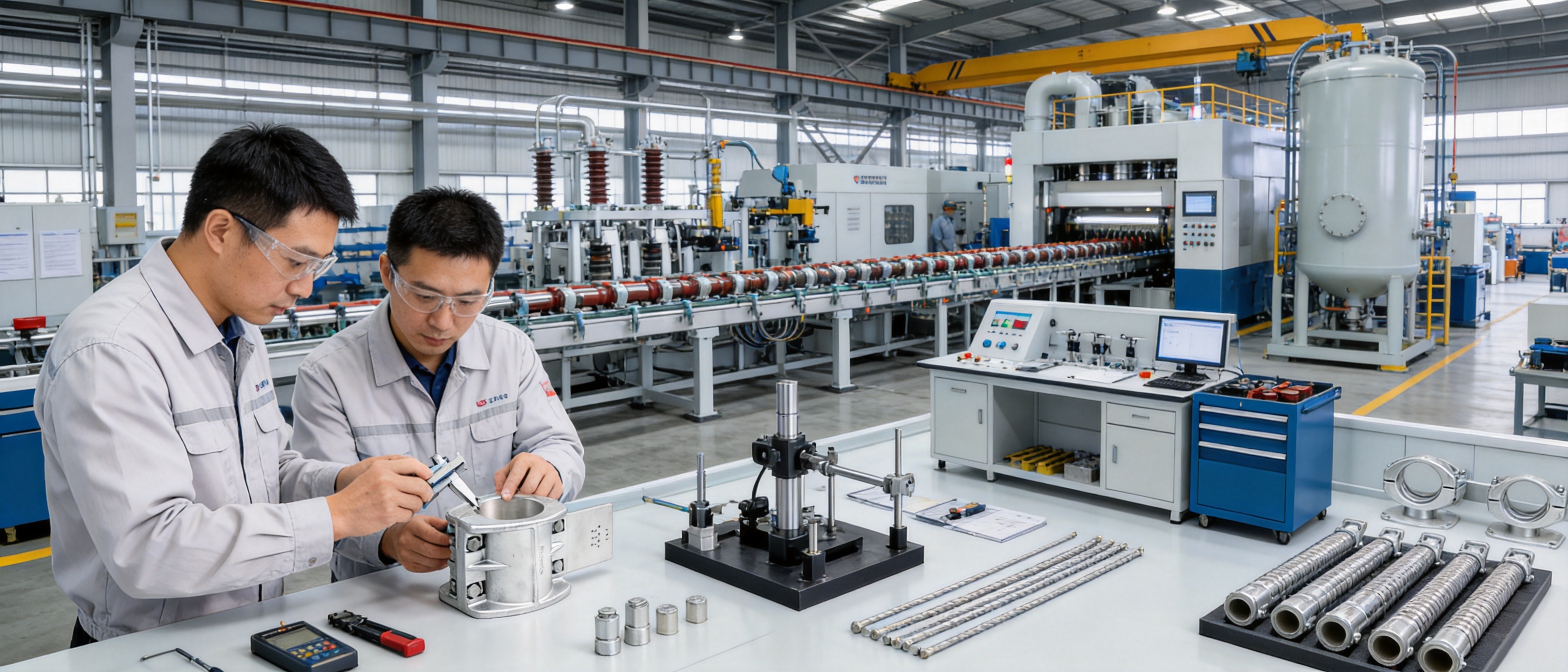
Jiangsu Wopeng Power Technology Co., Ltd. was founded in 2018 as a high-tech enterprise focused on high- and low-voltage busbar systems. Its production capabilities include vacuum casting systems, CNC machining equipment, and automated assembly technologies. These capabilities support the manufacture of busbar systems and related components with improved consistency and process control.
Vacuum Casting
Vacuum casting is used in the production of epoxy resin insulated busbar products. Removing air and moisture during casting helps reduce internal voids and improves insulation integrity. A controlled vacuum casting process can also improve resin impregnation, surface quality, dimensional consistency, and resistance to partial discharge.
For support-related products, the same focus on controlled material processing is valuable. Insulating components must be free from cracks, voids, excessive flash, and dimensional deformation. Stable molding and curing conditions support reliable performance from one production batch to the next.
CNC Machining
CNC machining provides accurate control of holes, slots, threads, contact surfaces, and other critical dimensions. Dimensional accuracy is important because the support must align with the conductor and mounting structure. Incorrect hole positions or uneven contact surfaces can introduce stress, make installation difficult, and affect long-term stability.
CNC equipment also supports flexible production for customized orders. When a project requires special mounting dimensions, modified clearances, or a particular interface, digital machining processes can produce the required configuration more consistently than manual modification.
Automated Assembly
Automated assembly technologies help control repeatable operations such as component positioning, fastening, and subassembly preparation. Automation reduces variation caused by manual handling and improves production efficiency for standardized products.
Automation does not replace engineering judgment or final inspection. Instead, it creates a stable production base while quality personnel verify critical dimensions, torque values, surface conditions, and electrical properties. This combination of automation and inspection is especially useful for products used in safety-critical power systems.
Quality Management and Inspection
Each product undergoes standardized inspection processes that may include high-voltage testing, insulation testing, mechanical verification, dimensional checks, and routine quality inspection. Testing cooperation with third-party institutions provides independent validation of safety and performance for applicable products and projects.
A complete quality system should begin with incoming material inspection and continue through manufacturing, assembly, final testing, packing, and delivery. Traceability enables the manufacturer and customer to identify the production batch, material information, test results, and configuration of supplied components. This supports long-term maintenance and technical service.
9. Applications in Power Distribution and Infrastructure
Bus-bar supports are used in a wide range of electrical installations. The correct selection depends on voltage level, current rating, conductor type, fault current, installation environment, support spacing, and the structure to which the component will be attached.
Switchgear and Distribution Cabinets
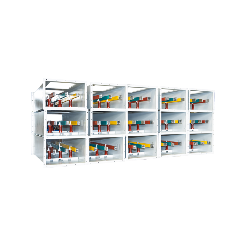
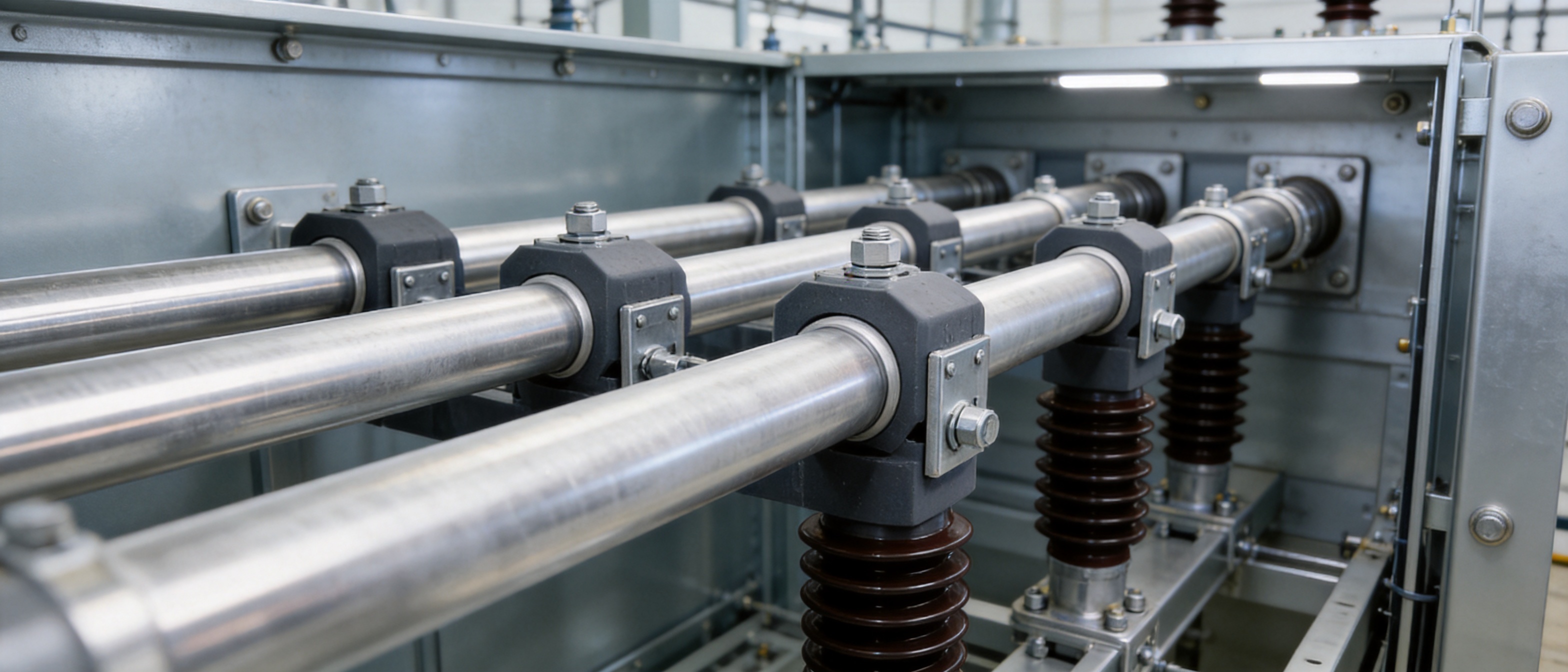
In low- and medium-voltage switchgear, supports hold copper or aluminum busbars in precise phase arrangements. They must fit within the enclosure while maintaining insulation distance and allowing access for inspection and connection. Fixed support types are suitable for busbar sections that must remain stable during switching and fault events.
Industrial Power Distribution
Factories and process plants often have high continuous loads and demanding environmental conditions. Motors, variable-frequency drives, welding equipment, furnaces, and other loads can produce heat and vibration. Strong supports with suitable insulation and corrosion protection help maintain the reliability of the distribution assembly.
Transformer Stations and Substations
Transformer stations require dependable connections between transformers, switchgear, feeders, and overhead or tubular busbar systems. Mechanical forces can be significant because of high fault levels and large conductor dimensions. Type MGG fixed hardware, Type MGF end caps, tension clamps, and supporting strands can be combined according to the station layout.
Renewable Energy Facilities
Wind farms and solar power facilities contain extensive power collection and grid connection equipment. Wind turbines introduce vibration and cyclic movement, while outdoor solar installations experience ultraviolet exposure, temperature changes, dust, and moisture. Corrosion-resistant and vibration-conscious support systems can help maintain long-term electrical reliability.
Rail Transit and Large Commercial Facilities
Rail transit systems require stable power distribution under vibration, movement, and high utilization. Large commercial buildings also depend on compact, high-current distribution systems that can operate safely with limited maintenance access. Reliable support hardware helps protect conductor alignment and insulation in these continuously operating facilities.
10. Selection Guide for Bus-Bar Supports
Selecting a support should begin with a clear understanding of the application. The following factors should be reviewed before ordering.
Conductor Type and Diameter
Confirm whether the busbar is tubular, rectangular, flat, copper, aluminum, or another configuration. For tubular busbars, measure the actual outer diameter and, where an end cap is required, the inner diameter as well. The Type MGG and Type MGF ranges should be matched to the specified dimensions rather than selected only by nominal product name.
Electrical Voltage and Current
Identify the operating voltage, insulation level, continuous current, prospective short-circuit current, and fault duration. These values influence support spacing, insulation distance, material requirements, and the need for reinforced hardware.
Mechanical Loading
Calculate conductor weight, span length, wind load, vibration, seismic force, thermal movement, and electromagnetic force. Tension clamps should be selected according to the required grip strength and steel strand diameter. When conditions are demanding, reinforced supports or damping options should be considered.
Environmental Conditions
Assess whether the support will be installed indoors, outdoors, underground, near the coast, in a chemical plant, or in a high-humidity location. Temperature range, ultraviolet exposure, salt spray, pollution level, and cleaning requirements should be included in the selection process.
Installation and Maintenance
Consider access for assembly, required tools, fastening method, inspection intervals, and replacement procedures. A support that is technically suitable but difficult to install may increase labor cost and create greater opportunity for assembly errors. Standardized dimensions and clear installation documentation can improve project efficiency.
Certification and Documentation
Request technical drawings, material specifications, test reports, installation instructions, and quality certificates as appropriate. For large infrastructure projects, customers may also require inspection plans, batch traceability, third-party verification, and customized documentation packages.
11. Installation Recommendations
Before installation, inspect all supports, clamps, end caps, fasteners, and busbar surfaces. Confirm that there are no cracks, deformation, damaged coatings, contamination, or missing parts. Components with visible damage should not be installed without technical evaluation.
Verify the support spacing and mounting orientation against the approved design drawings. The support should be installed on a stable structure capable of carrying the mechanical load. Fasteners should be tightened using the specified torque, and locking methods should be applied where required by the design.
Busbars should be positioned without forcing them into alignment through excessive bending or side loading. Forced alignment can transfer stress to the support, clamp, or connection point. Thermal expansion allowances should be respected where the system design includes sliding or expansion points.
When installing galvanized hardware, avoid unnecessary damage to the protective coating. If the coating is cut or heavily scratched, the affected area should be treated using an approved repair method. Dissimilar metal contact should also be reviewed to reduce the risk of galvanic corrosion.
After assembly, inspect phase spacing, conductor alignment, connection tightness, support engagement, end-cap seating, and clearance to grounded structures. Electrical testing should be completed according to the project requirements before energization.
12. Maintenance and Inspection
A well-designed support system requires less maintenance, but it should not be ignored after commissioning. Routine inspection helps identify corrosion, loose fasteners, cracks, contamination, overheating, or conductor movement before these conditions become serious failures.
During visual inspection, check for coating damage, rust, discoloration, cracked insulation, deformation, and signs of tracking or flashover. In outdoor systems, inspect for water accumulation, salt deposits, bird contamination, and ultraviolet degradation.
Thermal inspection can identify abnormal heating at connections or interfaces. A localized temperature rise may indicate high contact resistance, loose fastening, contamination, or excessive current. Mechanical inspections should verify that supports remain securely attached and that the busbar has not shifted from its designed position.
Cleaning methods should be compatible with the insulating material and environmental conditions. Abrasive tools and aggressive solvents may damage the surface. Maintenance personnel should follow the equipment manufacturer's recommendations and ensure that the system is safely isolated before working near energized components.
13. Customization and OEM Support
Power distribution projects often involve special dimensions, unusual mounting structures, demanding environmental conditions, or specific documentation requirements. A professional bus-bar supports manufacturer should be able to review drawings, confirm load conditions, recommend a suitable configuration, and provide custom dimensions where required.
OEM support may include customized support geometry, modified mounting holes, special end-cap dimensions, reinforced structures, alternative surface treatments, project-specific packaging, and identification marks. Engineering cooperation at the design stage can prevent later modifications and reduce installation risk.
Jiangsu Wopeng Power Technology Co., Ltd. provides customized OEM solutions for insulated busbars, tubular busbar systems, and related accessories. Its technical team includes engineers, technical specialists, and production professionals with experience in power equipment technology. This combination allows the company to support projects from product selection and engineering review through manufacturing, inspection, and delivery.
Customization should always be based on verified technical information. Customers should provide conductor dimensions, voltage level, current rating, short-circuit data, support span, environmental conditions, mounting drawings, and applicable standards. The more complete the information, the more accurately the support can be designed and validated.
14. Company Manufacturing Strength and Product Portfolio
Jiangsu Wopeng Power Technology Co., Ltd. focuses on the development and manufacture of high- and low-voltage busbar systems. Its product portfolio includes 35 kV epoxy resin vacuum-cast tube busbars, low-voltage cast-resin busways, copper and aluminum tubular busbars, wind power tube busbars, compact busbar systems, and sliding contact line systems.
This broader product portfolio is valuable when selecting bus-bar supports because accessories should be compatible with the complete power transmission system. A manufacturer that understands conductors, insulation, cast-resin technologies, enclosures, and connection methods can evaluate support requirements in a more integrated way than a supplier focused only on individual metal parts.
The company's products operate in more than 17 provinces and serve applications in power generation, substations, wind energy, industrial manufacturing, rail transit, and large commercial facilities. This field experience provides practical insight into different environmental conditions, installation methods, and customer requirements.
Modern production lines, vacuum casting systems, CNC equipment, and automated assembly technologies support consistent manufacturing. Standardized high-voltage tests, insulation tests, mechanical verification, and routine quality checks provide multiple control points before products are released. Cooperation with third-party testing institutions adds independent technical verification where required.
The combination of engineering capability, manufacturing resources, product breadth, and quality management makes the company suitable for customers seeking a long-term busbar system partner rather than a one-time hardware supplier.
15. Frequently Asked Questions
Q1: What are Bus-bar Supports used for?
Bus-bar Supports are used to hold, position, insulate, and stabilize busbars in switchgear, distribution cabinets, substations, transformer stations, industrial power systems, and other electrical installations. They help maintain phase spacing, support conductor weight, and resist movement caused by vibration, thermal expansion, and short-circuit forces.
Q2: What tubular busbar diameters are supported by Type MGG fixed hardware?
Type MGG fixed hardware is compatible with tubular busbar outer diameters from Φ50 mm to Φ180 mm. Standard and reinforced models are available for different mechanical requirements.
Q3: What is the function of Type MGF end caps?
Type MGF end caps seal the ends of tubular busbars, help protect the interior of the tube, and provide controlled termination geometry. Standard, damping, and terminal-ball types are available for different applications.
Q4: What is the advantage of the damping end-cap type?
The damping type includes LGJ series damping wires to improve resistance to vibration and seismic movement. It is suitable for installations where wind, mechanical vibration, earthquake loads, or long-term oscillation require additional control.
Q5: What steel strand diameters are suitable for the tension clamps?
The tension clamps are compatible with steel strand diameters from Φ7.8 mm to Φ16.0 mm. Grip strength options range from 45 kN to 187 kN, depending on the selected design and configuration.
Q6: Why is hot-dip galvanized steel used for the hardware?
Hot-dip galvanized steel provides high mechanical strength and improved corrosion resistance. The zinc coating, specified at a thickness of at least 85 μm for the applicable components, helps protect the steel in outdoor and industrial environments.
Q7: What is the difference between standard and reinforced fixed hardware?
Reinforced fixed hardware is designed for applications with greater mechanical loading, higher short-circuit forces, heavier conductors, longer support spans, or more severe vibration. The correct choice should be based on engineering calculations rather than appearance alone.
Q8: What insulating materials are commonly used in bus-bar supports?
DMC and SMC composite materials are commonly used because they provide excellent insulation, high mechanical strength, flame resistance, and good thermal stability. The appropriate material depends on the support geometry, operating temperature, mechanical load, and application environment.
Q9: Are these support systems suitable for medium-voltage applications?
Yes. The relevant support and tubular busbar systems can be configured for medium-voltage applications, including systems up to 35 kV where the complete design, insulation coordination, clearances, and test requirements are satisfied.
Q10: How should customers select a support for a new project?
Customers should provide the busbar type and dimensions, operating voltage, continuous current, short-circuit current, fault duration, support spacing, installation environment, mounting structure, and applicable standards. These details allow the manufacturer to recommend the correct support, end cap, clamp, or customized configuration.
Q11: Can support hardware be customized?
Yes. Customization may include dimensions, mounting holes, reinforcement, surface protection, end-cap configuration, packaging, and project documentation. Engineering review is recommended before production to confirm mechanical and electrical compatibility.
Q12: What testing is important for bus-bar supports?
Depending on the product and application, important evaluations include dimensional inspection, mechanical strength verification, insulation resistance, high-voltage testing, contact resistance, environmental testing, salt spray testing, ultraviolet aging, temperature cycling, and fatigue testing.
Q13: How can support service life be extended?
Use the correct support spacing and fastening torque, protect galvanized surfaces from damage, prevent contamination and water accumulation, inspect for corrosion and loosening, and perform electrical and thermal checks at the intervals required by the project maintenance plan.
16. Conclusion
Bus-bar supports are fundamental components in safe and reliable power distribution. Their responsibilities extend beyond holding a conductor in place. They preserve electrical clearances, resist short-circuit forces, manage vibration, support thermal stability, protect against environmental degradation, and contribute to the overall service life of the busbar system.
The product range described here combines Type MGG fixed hardware, Type MGF end caps, damping options, tension clamps, and supporting steel-cored aluminum strands. Broad dimensional compatibility, reinforced mechanical designs, hot-dip galvanized steel, controlled contact resistance, anti-corona considerations, environmental testing, and standardized manufacturing provide advantages over ordinary support hardware.
Jiangsu Wopeng Power Technology Co., Ltd. strengthens these product advantages through engineering expertise, vacuum casting, CNC machining, automated assembly, quality inspection, and third-party testing cooperation. Its wider portfolio of insulated busbars, tubular busbars, busways, compact busbar systems, and sliding contact line systems allows customers to obtain coordinated solutions for complete power transmission and distribution projects.
For customers selecting a bus-bar supports manufacturer, the most important criteria are technical compatibility, mechanical reserve, insulation reliability, corrosion protection, manufacturing consistency, documentation, and after-sales engineering support. When these factors are evaluated together, a properly designed support system can deliver stable performance in medium- and low-voltage distribution systems, substations, renewable energy facilities, industrial plants, and other critical infrastructure.
References
GB 1179-83, Aluminum Stranded Wires and Steel-Reinforced Aluminum Stranded Wires.
UL 94, Tests for Flammability of Plastic Materials for Parts in Devices and Appliances.
IEC 62271 Series, High-Voltage Switchgear and Controlgear.
IEC 61439 Series, Low-Voltage Switchgear and Controlgear Assemblies.
IEC 60071 Series, Insulation Coordination.
ISO 1461, Hot Dip Galvanized Coatings on Fabricated Iron and Steel Articles.
ISO 9223, Corrosion of Metals and Alloys—Corrosivity of Atmospheres.
IEC 60068 Series, Environmental Testing.
IEEE Technical Guides on Short-Circuit Mechanical Forces in Busbar Systems.
Manufacturer technical data for Type MGG fixed hardware, Type MGF end caps, tension clamps, and supporting steel-cored aluminum strands.
Product: Bus-bar Supports (Fixed Support Type)




-
 +86-180 3625 3000
-
 admin@wpbusbar.com
-
 No. 8, Yanjin Road, Chengxi Industrial Park, Shanyang Town, Baoying County, Yangzhou City, Jiangsu Province, China
Copyright © Jiangsu Wopeng Power Technology Co., Ltd.
All Rights Reserved.
 Custom Insulated Bus Bar Manufacturer
Tubular Busbar System Factory